EP0261036A2 - Vorrichtung zum Legen von Fliesen - Google Patents
Vorrichtung zum Legen von Fliesen Download PDFInfo
- Publication number
- EP0261036A2 EP0261036A2 EP87402088A EP87402088A EP0261036A2 EP 0261036 A2 EP0261036 A2 EP 0261036A2 EP 87402088 A EP87402088 A EP 87402088A EP 87402088 A EP87402088 A EP 87402088A EP 0261036 A2 EP0261036 A2 EP 0261036A2
- Authority
- EP
- European Patent Office
- Prior art keywords
- tile
- surface portion
- vibrator
- air
- enclosure
- Prior art date
- Legal status (The legal status is an assumption and is not a legal conclusion. Google has not performed a legal analysis and makes no representation as to the accuracy of the status listed.)
- Granted
Links
- 239000000853 adhesive Substances 0.000 claims abstract description 14
- 230000001070 adhesive effect Effects 0.000 claims abstract description 14
- 239000000463 material Substances 0.000 claims abstract description 11
- 125000006850 spacer group Chemical group 0.000 claims description 19
- 230000001419 dependent effect Effects 0.000 claims description 4
- 238000010276 construction Methods 0.000 description 4
- 239000004570 mortar (masonry) Substances 0.000 description 4
- 239000004568 cement Substances 0.000 description 1
- 230000001939 inductive effect Effects 0.000 description 1
Images


Classifications
-
- E—FIXED CONSTRUCTIONS
- E04—BUILDING
- E04F—FINISHING WORK ON BUILDINGS, e.g. STAIRS, FLOORS
- E04F21/00—Implements for finishing work on buildings
- E04F21/18—Implements for finishing work on buildings for setting wall or ceiling slabs or plates
- E04F21/1838—Implements for finishing work on buildings for setting wall or ceiling slabs or plates for setting a plurality of similar elements
- E04F21/1883—Implements for finishing work on buildings for setting wall or ceiling slabs or plates for setting a plurality of similar elements by simultaneously applying several elements, e.g. templates
- E04F21/1888—Implements for finishing work on buildings for setting wall or ceiling slabs or plates for setting a plurality of similar elements by simultaneously applying several elements, e.g. templates using suction-cups
Definitions
- This invention relates to an apparatus for laying tiles or the like. More particularly, the invention relates to a device which enables to lay tiles on a surface with ease and uniformity, and has the advantage that the work can be done by an inexperienced worker.
- the laying of tiles on a surface is normally carried out by hand.
- a surface such as a floor or a wall
- an adhesive material such as a cement or a mortar
- the tile is placed in its proper location and is lightly knocked down into the adhesive material until it attains the exact position which is desired.
- This needs highly skilled workers and is quite time-consuming.
- an apparatus for laying tiles or the like on a surface which comprises a body means associated with the body for holding a tile over a surface portion covered with an adhesive material, the surface portion being intended to receive the tile and for allowing the tile to contact the adhesive, vibration means also associated with the body, operative when the tile is in contact with the surface portion covered with the adhesive material to cause the tile to become embedded in the adhesive material thereby being fixed on the surface portion, and means enabling the holding means to release the tile after the latter has been fixed on the surface portion.
- the apparatus additionally comprises levelling means enabling to lay the tile along horizontal or vertical levels.
- the apparatus comprises joint spacer means enabling to space a tile from a neighboring tile, a distance corresponding to the predetermined width of a joint to be formed between two adjacent tiles.
- the holding means comprises a suction cup mounted on the body and means to operatively connect the cup to an air compressor, the suction cup being capable of holding the tile when operatively connected to the air compressor and of releasing the tile when contact with the air compressor is closed.
- the vibration means comprises a vibrator mounted in the body to induce a vibration in the body, the vibration being thereby communicated to the suction cup and consequently to the tile when the latter is being laid on the surface portion.
- the body comprises an enclosure, the latter comprising the vibrator and a vacuum generator.
- the vacuum generator is operatively connected to the suction cup for operating it.
- a handle is mounted on the enclosure, air outlet means are provided on the handle for connection to the air compressor by means of an air hose.
- An air duct is provided in the handle which also includes a manifold. The latter is connected to the air duct and has a first and a second outlet. A first air connection is provided between the first air outlet and the vacuum generator, and a second air connection is provided between the second air outlet and the vibrator.
- the apparatus comprises a pair of extendable arms laterally extending from the enclosure on its front and back sides, adjustable legs at the ends of the arms, bubble levels on the arms to adjust the horizontal level of the tile, the extendable legs enabling to place at least one leg on a tile which has already been laid while at least another leg is directly placed on the surface portion.
- joint spacers dependent from each arm and parallel with the legs to enable to correctly space a tile relative to adjoining tiles so as to form a joint with the predetermined width.
- the apparatus comprises a rectangular side arm which is perpendicular to both extendable lateral arms, and an adjustable leg is provided on the outer side of the rectangular side arm.
- the rectangular side arm is provided with joint spacers which are dependent from both lateral sides of the rectangular side arm, and second bubble levels to adjust the vertical level of a tile mounted on a wall.
- the apparatus comprises a secondary rectangular handle laterally projecting from the enclosure opposite the rectangular side arm to further help in placing a tile in a proper location.
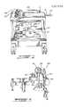
- the apparatus mainly consists of enclosure 1, a suction cup 3, a vibrator 5, a control handle 7, laterally extendable arms 9a and 9b, each provided with corresponding extendable legs 11a, 11b, rectangular side arm 13 also provided with an extendable leg 13a, and a secondary placement handle 15.
- the enclosure 1 has the general shape of a box with the top 17 being slightly curved mainly for design purposes.
- the suction cup 3 is of a type well known to those skilled in the art with the lowermost portion being shaped somewhat like an inverted teacup so as to hold a tile 19 over a surface portion 20 on which the tile is intended to be disposed by means of an adhesive such as mortar as shown in Fig. 1. This is made possible by having the suction cup connected to an air compressor (not shown). More details of the operation will be given hereinbelow.
- the suction cup 3 is operatively connected in known manner to a vacuum generator 21 of standard construction, and both the vibrator 5 (of known construction) and the vacuum generator 21 are mounted in known manner on the base 23 of the enclosure 1. It will therefore be seen by any one skilled in the art that once the vibrator 5 starts to vibrate, this will produce a corresponding vibration in the entire enclosure 1 and therefore the suction cup 3 will start to vibrate.
- the U-shaped control handle 7 consists of an upper straight bar 25 and two downwardly extending legs 27,29 fixed in known manner to the enclosure 1.
- the handle 7 has an air outlet 31 which is intended to be connected to air hose 33 which, in turn, is connected to an air compressor (not shown).
- An air duct 35 (shown in dotted lines in Figs. 1 and 2) extends through the upper straight bar 25 of the handle 7 until it reaches a manifold 37 illustrated in Fig. 3, which is connected in known manner to the air duct 35.
- the manifold 37 has two air outlets 39,41.
- an air connection 43 between air outlet 41 and the vacuum generator 5, and another air connection 45, the latter being mounted between air outlet 39 and the vibrator 5.
- a vacuum valve 47 (of known construction)
- the vacuum generator 5 becomes operative to enable the suction cup 3 to hold a tile 19 as shown in Fig. 1.
- the vibrator valve 49 by opening the vibrator valve 49, the vibrator 5 starts to induce a vibration in the enclosure 1 to cause the suction cup 3 and thereby the tile 19 to vibrate when the latter is laid on a surface portion.
- each arm 9a, 9b comprises an adjustable leg 11a, 11b which is mounted in a longitudinal slot 53a, 53b provided in arm 9a, 9b.
- the leg is provided with a threaded member 55a, 55b which extends through the slot 53a, 53b and the adjustment of the leg 11a, 11b along arm 9a, 9b is made possible by tightening the threaded member 55a, 55b with a wing nut 57a, 57b at a desired location along the arm 9a, 9b.
- Each leg 11a, 11b is provided with a well known height adjustable pad 59a, 59b.
- each arm 9a, 9b is provided with a spacer housing 61a, 61b terminated by a spacer 62a, 62b.
- the upper end of each spacer housing 61a, 61b is provided with a threaded member 63a, 63b similar to threaded member 55a, 55b.
- the spacer 63a, 63b can be placed at a desired location by sliding the housing 61a, 61b along slot 53a, 53b and tightening it by means of wing nut 65a, 65b.
- a bubble level 67 is mounted in known manner on arm 9a to adjust the horizontal level of the apparatus and therefore of the tile 19.
- the apparatus according to the invention also comprises a rectangular side arm 13.
- this side arm 13 is rectangular and is mounted in known manner on the enclosure 1 to be perpendicular to both laterally extending arms 9a, 9b.
- the adjustable leg 13a is similar to legs 11a, 11b except that it is not movable along the outer side 67 of the rectangular side arm 13.
- the two lateral sides 69,71 of the rectangular side arm 13 are formed with slots 73,75 to permit the mounting of spacer housings 77,79 which are similar to housings 61a,61b.
- the spacer housings 77,79 are therefore provided with spacers 81,83, threaded members 85,87 and wing nuts 89,91.
- the rectangular side arm is provided with a bubble level 93 to adjust the vertical level of the apparatus and therefore of the tile when tiling a wall.
- the apparatus comprises a secondary rectangular handle 15 which laterally projects from the enclosure opposite the rectangular side arm 13. This secondary handle will further assist in placing a tile in a proper location.
- the vibrator 5 is used instead of having to knock on the tile 19 until the latter is in proper place, while the tile 19 is still held by the suction cup 3.
- the vibrator 5 goes on and forces the tile to set in the mortar (not shown) until all air bubbles have been removed and proper location of the tile on the surface portion 20 such as a floor or wall has been achieved.
- each extendable arm 9a,9b and side arm 13 is provided with joint spacers 61a,61b,81,83.
- Each joint spacer has the thickness of a predetermined width of a joint to be formed between two adjoining tiles. So, when placing tile 19 adjacent two other tiles, it is merely necessary to visually rely on the joint spacers to make sure that a space corresponding to the joint to be formed between the two tiles will be left between them.
- the suction cup 101 is of a type well known to those skilled in in the art with the suction portion 111 forming the lowermost portion of the suction cup 101 and shaped somewhat like an inverted teacup so as to hold a tile 113, as shown in Fig. 4. This is made possible by having the suction cup connected to an air compressor (not shown) and more details of the operation will be given hereinbelow.
- the vibrator 103 is mounted over the suction cup 101 and is associated therewith by any known means so as to induce a vibration in the suction cup 101 when the vibrator 103 is operatively connected to a source of power (not shown) capable of inducing vibrations in the vibrator.
- a vertical support consisting of a pair of posts 115, 117 is mounted on the suction cup 101 in the manner shown in Fig. 4 of the drawings, to extend on both sides of and above the upper surface of the vibrator 103.
- a control handle 105 consisting of a straight bar is mounted on the vertical support consisting of the two posts 115, 117, again as shown in Fig. 4 of the drawings.
- the handle 105 has two air outlets 119, 121 which are intended to be connected to air hose 123 which, in turn, is connected to an air compressor (not shown).
- Air duct 125 extends from the control handle 105 to the vibrator 103 to produce a a vibration therein and in the suction cup 101.
- Air duct 125 extends from the control handle 105 to the suction cup 101 via vacuum pump 126 and is responsible for creating the desired suction in the suction cup 101.
- the arms 107a, 107b, 107c and the legs 109a, 109b, 109c there are provided three arms 107a, 107b, 107c. Two of those arms 107a and 107b are mounted on the posts 115, 117 in known manner to project from the suction cup 101, in the manner shown in the drawings. It will be noted that these two arms are in continuation of one another along a straight imaginary line.
- the other arm 107c is perpendicular to the first two arms 107a, 107b and is mounted on the vibrator 103, such as shown in Fig. 5 of the drawings.
- Each arm 107a, 107b, 107c contains an extendable portion 135a, 135b, 135c which can be adjusted to any desired length by means of any well known means schematically illustrated at 137.
- the legs 109a, 109b, 109c are also extendable and this is made possible by providing a member 139 which can slide over the fixed portion 141 of the leg 109a, 109b, 109c.
- a mechanism 143 similar to the mechanism 137 enables to fixedly adjust the length of the leg 109a, 109b, 109c.
- each fixed portion 141 of legs 109a, 109b, 109c has a sliding portion 139a, 139b, 139c which contains a tilt bubble 147.
- the idea is to enable to lay a tile 113 in a perfect horizontal position whether or not there are tiles adjacent the the tiles to be laid.
- leg 109b and leg 109c are shortened by the distance corresponding to the thickness of tiles 113a and 113b, while leg 109c is fully extended, as particularly shown in Fig. 4 of the drawings, to rest on the floor. It is then possible to lay the tile 113 and to adjust the level thereof by means of the tilt bubble levels 145.
- a vibrator is used instead of having to knock on the tile until the latter is in proper place, while the tile 113 is still held by the suction cup 101.
- the vibrator 103 goes on and forces the tile to set in the mortar (not shown) until all air bubbles have been removed and proper location of the tile on the surface portion 120 such as a floor has been achieved.
- each extendable arm portion 135a, 135b, 135c is provided with joint spacers 149.
- Each joint spacer 149 has the thickness of a predetermined width of a joint 151 to be formed between two tiles 113 and 113a. So, when placing tile 113 adjacent tiles 113a and 113b, it is merely necessary to visually rely on the joint spacers 149 to make sure that a space 151 corresponding to the joint to be formed between the two tiles will be left between them.
Landscapes
- Engineering & Computer Science (AREA)
- Architecture (AREA)
- Civil Engineering (AREA)
- Structural Engineering (AREA)
- Finishing Walls (AREA)
- Road Paving Structures (AREA)
- Floor Finish (AREA)
- Paper (AREA)
- Buildings Adapted To Withstand Abnormal External Influences (AREA)
- Road Signs Or Road Markings (AREA)
- Catching Or Destruction (AREA)
Priority Applications (1)
| Application Number | Priority Date | Filing Date | Title |
|---|---|---|---|
| AT87402088T ATE67550T1 (de) | 1986-09-18 | 1987-09-18 | Vorrichtung zum legen von fliesen. |
Applications Claiming Priority (2)
| Application Number | Priority Date | Filing Date | Title |
|---|---|---|---|
| CA000518519A CA1285787C (en) | 1986-09-18 | 1986-09-18 | Apparatus for laying tiles or the like |
| CA518519 | 1986-09-18 |
Publications (3)
| Publication Number | Publication Date |
|---|---|
| EP0261036A2 true EP0261036A2 (de) | 1988-03-23 |
| EP0261036A3 EP0261036A3 (en) | 1988-09-28 |
| EP0261036B1 EP0261036B1 (de) | 1991-09-18 |
Family
ID=4133964
Family Applications (1)
| Application Number | Title | Priority Date | Filing Date |
|---|---|---|---|
| EP87402088A Expired - Lifetime EP0261036B1 (de) | 1986-09-18 | 1987-09-18 | Vorrichtung zum Legen von Fliesen |
Country Status (8)
| Country | Link |
|---|---|
| US (1) | US4893451A (de) |
| EP (1) | EP0261036B1 (de) |
| AT (1) | ATE67550T1 (de) |
| AU (1) | AU603828B2 (de) |
| CA (1) | CA1285787C (de) |
| DE (1) | DE3773097D1 (de) |
| ES (1) | ES2024533B3 (de) |
| IL (1) | IL83921A (de) |
Cited By (1)
| Publication number | Priority date | Publication date | Assignee | Title |
|---|---|---|---|---|
| CN110984543A (zh) * | 2020-01-04 | 2020-04-10 | 绍兴多卡机械设备有限公司 | 一种地砖运输与铺设装置 |
Families Citing this family (21)
| Publication number | Priority date | Publication date | Assignee | Title |
|---|---|---|---|---|
| CA2066089C (en) * | 1992-04-15 | 1996-12-03 | Pietro Valente | Levelled cement spreader |
| US5867965A (en) * | 1995-03-10 | 1999-02-09 | Pilz; Jack | Tile setting machine |
| US6047520A (en) * | 1997-07-31 | 2000-04-11 | Caraballo; Abelardo | Floor tile holder, setter, and spacer; and table |
| US7493931B2 (en) * | 2003-08-20 | 2009-02-24 | Sure Set Manufacturing Inc. | Vibrating tile setting tool |
| US8011163B2 (en) * | 2007-11-13 | 2011-09-06 | Sebastian Bazzano | Methods and apparatus for laying marble tile flooring |
| JP5626997B2 (ja) * | 2011-02-24 | 2014-11-19 | パナホーム株式会社 | タイル押圧治具及びタイル押圧装置 |
| ITMO20110320A1 (it) * | 2011-12-09 | 2013-06-10 | Matteo Gessani | Apparecchio per il montaggio piastre di supporto dispositivi elettrici |
| US10384433B2 (en) | 2015-12-11 | 2019-08-20 | Suma Consulting and Investments, Inc. | Apparatus and method to extract an object from a base surface using vibration |
| ES2643870B1 (es) * | 2016-05-24 | 2018-09-13 | Francisco Javier LÓPEZ GONZÁLEZ | Dispositivo para extracción de elementos de recubrimiento de suelos |
| US10450736B2 (en) | 2018-02-02 | 2019-10-22 | Blue Tomato Llc | Modular light weight construction system based on pre-slotted panels and standard dimensional splines |
| USD861194S1 (en) | 2018-05-23 | 2019-09-24 | Blue Tomato Llc | Panel |
| US11015340B2 (en) | 2018-08-24 | 2021-05-25 | Blue Tomato Llc | Sealed envelope agricultural building constructions |
| US11697946B2 (en) | 2018-10-16 | 2023-07-11 | Blue Tomato, Llc | Pool or other below grade fluid containment |
| US11401724B2 (en) | 2018-10-16 | 2022-08-02 | Blue Tomato Llc | Below grade fluid containment |
| US11286658B2 (en) | 2018-12-10 | 2022-03-29 | Blue Tomato, Llc | Method for light weight construction using pre-slotted standard and transition panels |
| US11352775B2 (en) | 2018-12-10 | 2022-06-07 | Blue Tomato, Llc | Light weight construction system based on horizontally pre-slotted panels |
| US12188222B2 (en) | 2018-12-10 | 2025-01-07 | Blue Tomato, Llc | Frames and derivative modules based on light weight construction system with standard and transition panels |
| US10865560B1 (en) | 2018-12-10 | 2020-12-15 | Blue Tomato, Llc | Light weight post and beam construction system based on horizontally pre-slotted panels |
| US12480306B2 (en) | 2018-12-10 | 2025-11-25 | Blue Tomato, Llc | Method for constructing building using C-channel and standard and transition panels |
| USD994148S1 (en) | 2019-12-10 | 2023-08-01 | Blue Tomato, Llc | Construction panel |
| US12378782B1 (en) * | 2024-03-16 | 2025-08-05 | Michael Perez | Tile setting device |
Family Cites Families (18)
| Publication number | Priority date | Publication date | Assignee | Title |
|---|---|---|---|---|
| DE224351C (de) * | ||||
| DE158538C (de) * | ||||
| US1825320A (en) * | 1927-05-27 | 1931-09-29 | Kuerts Ernst | Block paving machine and the like |
| DE698453C (de) * | 1936-12-04 | 1940-11-11 | Heinrich Buehrmann | Strassenpflastersetzmaschine |
| DE811152C (de) * | 1948-12-02 | 1951-08-16 | Friedrich Karl Ruckert | Verfahren und Geraet zur Herstellung von Belaegen aus Steinholzmasse |
| FR1207986A (fr) * | 1957-11-15 | 1960-02-19 | Procédé et appareil pour la fixation d'objets plats contre des parois au moyen d'un adhésif ou de ciment | |
| DE1683672A1 (de) * | 1966-02-04 | 1971-02-25 | Richard Vetter | Zur Anbringung von Stein- oder Plattenreihen dienende Vorrichtung fuer das Baugewerbe |
| DE1683154A1 (de) * | 1967-12-11 | 1970-05-14 | Kramer Dieter W | Vorrichtung zum Verlegen von Platten oder Fliesen |
| CA894681A (en) * | 1969-08-01 | 1972-03-07 | Jacobucci Romeo | Tile holding and placement device |
| SE7510182L (sv) * | 1974-11-04 | 1976-05-05 | Krueger Karl | Sett och anordning for plattsettning pa veggytor |
| SU657108A1 (ru) * | 1976-08-23 | 1979-04-15 | Министерство Строительства Литовской Сср | Укладчик плит |
| US4106259A (en) * | 1976-10-18 | 1978-08-15 | Taylor Smith Ernest J | Automatic apparatus for laying block units |
| SU612991A1 (ru) * | 1976-11-25 | 1978-06-30 | Войсковая Часть 64688 | Укладчик плит |
| SU779492A1 (ru) * | 1978-05-15 | 1980-11-15 | Ростовский-На-Дону Научно-Исследовательский Институт Академии Коммунального Хозяйства Им.К.Д.Памфилова | Укладчик плит |
| US4227834A (en) * | 1979-01-16 | 1980-10-14 | Terrafix Erosion Control Products, Inc. | Block laying machine |
| US4583343A (en) * | 1983-09-15 | 1986-04-22 | Camp Dariel R | Tile setting kit |
| DE3411882A1 (de) * | 1984-03-30 | 1985-10-10 | Kubat, Hannchen, 8901 Dasing | Vorrichtung zum verlegen von fliesen oder platten |
| NL8503510A (nl) * | 1985-12-19 | 1987-07-16 | Stonemac Bv | Inrichting voor het in onderling verband aangrijpen van tegels. |
-
1986
- 1986-09-18 CA CA000518519A patent/CA1285787C/en not_active Expired - Lifetime
-
1987
- 1987-09-16 AU AU78601/87A patent/AU603828B2/en not_active Ceased
- 1987-09-16 IL IL83921A patent/IL83921A/xx not_active IP Right Cessation
- 1987-09-17 US US07/097,579 patent/US4893451A/en not_active Expired - Fee Related
- 1987-09-18 ES ES87402088T patent/ES2024533B3/es not_active Expired - Lifetime
- 1987-09-18 AT AT87402088T patent/ATE67550T1/de not_active IP Right Cessation
- 1987-09-18 EP EP87402088A patent/EP0261036B1/de not_active Expired - Lifetime
- 1987-09-18 DE DE8787402088T patent/DE3773097D1/de not_active Expired - Lifetime
Cited By (1)
| Publication number | Priority date | Publication date | Assignee | Title |
|---|---|---|---|---|
| CN110984543A (zh) * | 2020-01-04 | 2020-04-10 | 绍兴多卡机械设备有限公司 | 一种地砖运输与铺设装置 |
Also Published As
| Publication number | Publication date |
|---|---|
| AU7860187A (en) | 1988-03-24 |
| US4893451A (en) | 1990-01-16 |
| IL83921A (en) | 1991-03-10 |
| IL83921A0 (en) | 1988-02-29 |
| CA1285787C (en) | 1991-07-09 |
| EP0261036B1 (de) | 1991-09-18 |
| ATE67550T1 (de) | 1991-10-15 |
| DE3773097D1 (de) | 1991-10-24 |
| ES2024533B3 (es) | 1992-03-01 |
| AU603828B2 (en) | 1990-11-29 |
| EP0261036A3 (en) | 1988-09-28 |
Similar Documents
| Publication | Publication Date | Title |
|---|---|---|
| EP0261036B1 (de) | Vorrichtung zum Legen von Fliesen | |
| CA1232151A (en) | Concrete screed | |
| EP0482254A1 (de) | Schleifblock mit Stiel und Staubabsaugung | |
| EP0566467A1 (de) | Vorrichtung zum ebenen Ausbringen eines zementhaltigen Materials | |
| ATE147458T1 (de) | Stützelement zur benutzung beim giessen von betonfussböden | |
| US4316715A (en) | Vibratory concrete screed having an adjustable extension bracket | |
| JPS587769Y2 (ja) | 配線ボツクス類の固定装置 | |
| US4934643A (en) | Holder for screed rail | |
| KR940006330B1 (ko) | 타일 부착 장치 | |
| GB2254641A (en) | Brick laying and block laying. | |
| US4363618A (en) | Triangular truss screed having an end mounted guide bracket for engaging a wall-mounted support member | |
| PT86670B (pt) | Aparelho para assentamento de ladrilhos | |
| JPH01210567A (ja) | タイル張り装置 | |
| US3861111A (en) | Brick laying device | |
| EP0463280A1 (de) | Rüttelgerät für das Legen von Bodenbelägen, wie Marmorfliesen, keramischen Fliesen, Holzfliesen zur Parkettverlegung im Baugewerbe | |
| CN218147671U (zh) | 一种步砖施工装置 | |
| JP2634433B2 (ja) | 床パネルの取付構造 | |
| JPS6328742U (de) | ||
| JP2511635Y2 (ja) | 基礎天端設定用治具 | |
| JPH0526887Y2 (de) | ||
| KR840000677Y1 (ko) | 천정현수간용 이동식 고정구 | |
| CA1174070A (en) | Vibratory concrete screed system including an adjustable extension bracket | |
| JPS6311600Y2 (de) | ||
| JP2025140458A (ja) | 組立補助部材 | |
| JPH116182A (ja) | ユニットバスの支持構造 |
Legal Events
| Date | Code | Title | Description |
|---|---|---|---|
| PUAI | Public reference made under article 153(3) epc to a published international application that has entered the european phase |
Free format text: ORIGINAL CODE: 0009012 |
|
| AK | Designated contracting states |
Kind code of ref document: A2 Designated state(s): AT BE CH DE ES FR GB GR IT LI LU NL SE |
|
| PUAL | Search report despatched |
Free format text: ORIGINAL CODE: 0009013 |
|
| AK | Designated contracting states |
Kind code of ref document: A3 Designated state(s): AT BE CH DE ES FR GB GR IT LI LU NL SE |
|
| 17P | Request for examination filed |
Effective date: 19890215 |
|
| 17Q | First examination report despatched |
Effective date: 19900705 |
|
| GRAA | (expected) grant |
Free format text: ORIGINAL CODE: 0009210 |
|
| AK | Designated contracting states |
Kind code of ref document: B1 Designated state(s): AT BE CH DE ES FR GB GR IT LI LU NL SE |
|
| PG25 | Lapsed in a contracting state [announced via postgrant information from national office to epo] |
Ref country code: GR Free format text: LAPSE BECAUSE OF FAILURE TO SUBMIT A TRANSLATION OF THE DESCRIPTION OR TO PAY THE FEE WITHIN THE PRESCRIBED TIME-LIMIT Effective date: 19910918 |
|
| REF | Corresponds to: |
Ref document number: 67550 Country of ref document: AT Date of ref document: 19911015 Kind code of ref document: T |
|
| REF | Corresponds to: |
Ref document number: 3773097 Country of ref document: DE Date of ref document: 19911024 |
|
| ET | Fr: translation filed | ||
| ITF | It: translation for a ep patent filed | ||
| REG | Reference to a national code |
Ref country code: ES Ref legal event code: FG2A Ref document number: 2024533 Country of ref document: ES Kind code of ref document: B3 |
|
| PLBE | No opposition filed within time limit |
Free format text: ORIGINAL CODE: 0009261 |
|
| STAA | Information on the status of an ep patent application or granted ep patent |
Free format text: STATUS: NO OPPOSITION FILED WITHIN TIME LIMIT |
|
| 26N | No opposition filed | ||
| EPTA | Lu: last paid annual fee | ||
| EAL | Se: european patent in force in sweden |
Ref document number: 87402088.6 |
|
| PGFP | Annual fee paid to national office [announced via postgrant information from national office to epo] |
Ref country code: LU Payment date: 19970814 Year of fee payment: 11 |
|
| PGFP | Annual fee paid to national office [announced via postgrant information from national office to epo] |
Ref country code: FR Payment date: 19970825 Year of fee payment: 11 |
|
| PGFP | Annual fee paid to national office [announced via postgrant information from national office to epo] |
Ref country code: ES Payment date: 19970915 Year of fee payment: 11 |
|
| PGFP | Annual fee paid to national office [announced via postgrant information from national office to epo] |
Ref country code: AT Payment date: 19970923 Year of fee payment: 11 |
|
| PGFP | Annual fee paid to national office [announced via postgrant information from national office to epo] |
Ref country code: NL Payment date: 19970930 Year of fee payment: 11 |
|
| PGFP | Annual fee paid to national office [announced via postgrant information from national office to epo] |
Ref country code: SE Payment date: 19980810 Year of fee payment: 12 |
|
| PGFP | Annual fee paid to national office [announced via postgrant information from national office to epo] |
Ref country code: BE Payment date: 19980824 Year of fee payment: 12 |
|
| PGFP | Annual fee paid to national office [announced via postgrant information from national office to epo] |
Ref country code: GB Payment date: 19980907 Year of fee payment: 12 |
|
| PGFP | Annual fee paid to national office [announced via postgrant information from national office to epo] |
Ref country code: CH Payment date: 19980908 Year of fee payment: 12 |
|
| PG25 | Lapsed in a contracting state [announced via postgrant information from national office to epo] |
Ref country code: LU Free format text: LAPSE BECAUSE OF NON-PAYMENT OF DUE FEES Effective date: 19980918 Ref country code: AT Free format text: LAPSE BECAUSE OF NON-PAYMENT OF DUE FEES Effective date: 19980918 |
|
| PG25 | Lapsed in a contracting state [announced via postgrant information from national office to epo] |
Ref country code: ES Free format text: LAPSE BECAUSE OF THE APPLICANT RENOUNCES Effective date: 19980919 |
|
| PGFP | Annual fee paid to national office [announced via postgrant information from national office to epo] |
Ref country code: DE Payment date: 19981029 Year of fee payment: 12 |
|
| PG25 | Lapsed in a contracting state [announced via postgrant information from national office to epo] |
Ref country code: NL Free format text: LAPSE BECAUSE OF NON-PAYMENT OF DUE FEES Effective date: 19990401 |
|
| PG25 | Lapsed in a contracting state [announced via postgrant information from national office to epo] |
Ref country code: FR Free format text: LAPSE BECAUSE OF NON-PAYMENT OF DUE FEES Effective date: 19990531 |
|
| NLV4 | Nl: lapsed or anulled due to non-payment of the annual fee |
Effective date: 19990401 |
|
| REG | Reference to a national code |
Ref country code: FR Ref legal event code: ST |
|
| PG25 | Lapsed in a contracting state [announced via postgrant information from national office to epo] |
Ref country code: GB Free format text: LAPSE BECAUSE OF NON-PAYMENT OF DUE FEES Effective date: 19990918 |
|
| PG25 | Lapsed in a contracting state [announced via postgrant information from national office to epo] |
Ref country code: SE Free format text: THE PATENT HAS BEEN ANNULLED BY A DECISION OF A NATIONAL AUTHORITY Effective date: 19990929 |
|
| PG25 | Lapsed in a contracting state [announced via postgrant information from national office to epo] |
Ref country code: LI Free format text: LAPSE BECAUSE OF NON-PAYMENT OF DUE FEES Effective date: 19990930 Ref country code: CH Free format text: LAPSE BECAUSE OF NON-PAYMENT OF DUE FEES Effective date: 19990930 Ref country code: BE Free format text: LAPSE BECAUSE OF NON-PAYMENT OF DUE FEES Effective date: 19990930 |
|
| BERE | Be: lapsed |
Owner name: ANTONIETTA INVESTMENTS LTD Effective date: 19990930 |
|
| GBPC | Gb: european patent ceased through non-payment of renewal fee |
Effective date: 19990918 |
|
| EUG | Se: european patent has lapsed |
Ref document number: 87402088.6 |
|
| REG | Reference to a national code |
Ref country code: CH Ref legal event code: PL |
|
| PG25 | Lapsed in a contracting state [announced via postgrant information from national office to epo] |
Ref country code: DE Free format text: LAPSE BECAUSE OF NON-PAYMENT OF DUE FEES Effective date: 20000701 |
|
| REG | Reference to a national code |
Ref country code: ES Ref legal event code: FD2A Effective date: 20001102 |
|
| PG25 | Lapsed in a contracting state [announced via postgrant information from national office to epo] |
Ref country code: IT Free format text: LAPSE BECAUSE OF NON-PAYMENT OF DUE FEES;WARNING: LAPSES OF ITALIAN PATENTS WITH EFFECTIVE DATE BEFORE 2007 MAY HAVE OCCURRED AT ANY TIME BEFORE 2007. THE CORRECT EFFECTIVE DATE MAY BE DIFFERENT FROM THE ONE RECORDED. Effective date: 20050918 |