EP0261101B1 - Elément de construction et son procédé de fabrication - Google Patents
Elément de construction et son procédé de fabrication Download PDFInfo
- Publication number
- EP0261101B1 EP0261101B1 EP87890207A EP87890207A EP0261101B1 EP 0261101 B1 EP0261101 B1 EP 0261101B1 EP 87890207 A EP87890207 A EP 87890207A EP 87890207 A EP87890207 A EP 87890207A EP 0261101 B1 EP0261101 B1 EP 0261101B1
- Authority
- EP
- European Patent Office
- Prior art keywords
- structural element
- element according
- passage
- shafts
- sections
- Prior art date
- Legal status (The legal status is an assumption and is not a legal conclusion. Google has not performed a legal analysis and makes no representation as to the accuracy of the status listed.)
- Expired - Lifetime
Links
- 238000004519 manufacturing process Methods 0.000 title claims abstract description 21
- 238000000034 method Methods 0.000 title claims description 8
- 238000003754 machining Methods 0.000 claims description 3
- 239000007787 solid Substances 0.000 claims 1
- 230000009172 bursting Effects 0.000 description 1
- 238000010586 diagram Methods 0.000 description 1
- 238000006073 displacement reaction Methods 0.000 description 1
- 238000009415 formwork Methods 0.000 description 1
- 238000011065 in-situ storage Methods 0.000 description 1
- 239000003562 lightweight material Substances 0.000 description 1
- 238000012986 modification Methods 0.000 description 1
- 230000004048 modification Effects 0.000 description 1
Images
Classifications
-
- E—FIXED CONSTRUCTIONS
- E04—BUILDING
- E04B—GENERAL BUILDING CONSTRUCTIONS; WALLS, e.g. PARTITIONS; ROOFS; FLOORS; CEILINGS; INSULATION OR OTHER PROTECTION OF BUILDINGS
- E04B2/00—Walls, e.g. partitions, for buildings; Wall construction with regard to insulation; Connections specially adapted to walls
- E04B2/02—Walls, e.g. partitions, for buildings; Wall construction with regard to insulation; Connections specially adapted to walls built-up from layers of building elements
- E04B2/14—Walls having cavities in, but not between, the elements, i.e. each cavity being enclosed by at least four sides forming part of one single element
- E04B2/24—Walls having cavities in, but not between, the elements, i.e. each cavity being enclosed by at least four sides forming part of one single element the walls being characterised by fillings in some of the cavities forming load-bearing pillars or beams
-
- B—PERFORMING OPERATIONS; TRANSPORTING
- B28—WORKING CEMENT, CLAY, OR STONE
- B28B—SHAPING CLAY OR OTHER CERAMIC COMPOSITIONS; SHAPING SLAG; SHAPING MIXTURES CONTAINING CEMENTITIOUS MATERIAL, e.g. PLASTER
- B28B11/00—Apparatus or processes for treating or working the shaped or preshaped articles
- B28B11/08—Apparatus or processes for treating or working the shaped or preshaped articles for reshaping the surface, e.g. smoothing, roughening, corrugating, making screw-threads
- B28B11/0845—Apparatus or processes for treating or working the shaped or preshaped articles for reshaping the surface, e.g. smoothing, roughening, corrugating, making screw-threads for smoothing
-
- B—PERFORMING OPERATIONS; TRANSPORTING
- B28—WORKING CEMENT, CLAY, OR STONE
- B28B—SHAPING CLAY OR OTHER CERAMIC COMPOSITIONS; SHAPING SLAG; SHAPING MIXTURES CONTAINING CEMENTITIOUS MATERIAL, e.g. PLASTER
- B28B11/00—Apparatus or processes for treating or working the shaped or preshaped articles
- B28B11/12—Apparatus or processes for treating or working the shaped or preshaped articles for removing parts of the articles by cutting
-
- E—FIXED CONSTRUCTIONS
- E04—BUILDING
- E04B—GENERAL BUILDING CONSTRUCTIONS; WALLS, e.g. PARTITIONS; ROOFS; FLOORS; CEILINGS; INSULATION OR OTHER PROTECTION OF BUILDINGS
- E04B2/00—Walls, e.g. partitions, for buildings; Wall construction with regard to insulation; Connections specially adapted to walls
- E04B2/02—Walls, e.g. partitions, for buildings; Wall construction with regard to insulation; Connections specially adapted to walls built-up from layers of building elements
- E04B2002/0202—Details of connections
- E04B2002/0204—Non-undercut connections, e.g. tongue and groove connections
- E04B2002/0208—Non-undercut connections, e.g. tongue and groove connections of trapezoidal shape
-
- E—FIXED CONSTRUCTIONS
- E04—BUILDING
- E04B—GENERAL BUILDING CONSTRUCTIONS; WALLS, e.g. PARTITIONS; ROOFS; FLOORS; CEILINGS; INSULATION OR OTHER PROTECTION OF BUILDINGS
- E04B2/00—Walls, e.g. partitions, for buildings; Wall construction with regard to insulation; Connections specially adapted to walls
- E04B2/02—Walls, e.g. partitions, for buildings; Wall construction with regard to insulation; Connections specially adapted to walls built-up from layers of building elements
- E04B2002/0202—Details of connections
- E04B2002/0204—Non-undercut connections, e.g. tongue and groove connections
- E04B2002/0226—Non-undercut connections, e.g. tongue and groove connections with tongues and grooves next to each other on the end surface
Definitions
- the invention relates to a component which is essentially cuboid in shape and has two visible, two support and at least one abutting surface and is provided with at least one horizontal channel opening out on the abutting surface, and to a method for its production.
- Such components are known for example from AT-PSen 337 950, 339 008 and 348 724 and DE-U-8 009 618. They are mainly formwork blocks or panels made of lightweight materials. These have grooves on their abutting surfaces which, when the stones or slabs are placed next to one another, result in vertical shafts which are connected to the horizontal channels. These shafts and channels, the cross sections of which are generally round or oval, are poured with in-situ concrete, which results in a stable wall structure.
- a disadvantage of these components is that they have to be clamped before pouring in order to prevent the shafts from expanding on the abutting surfaces. This is not only time-consuming and costly, but also a frequent source of error due to possible carelessness.
- the aim of the invention is to eliminate the disadvantage shown. This is achieved in that at least one vertical shaft, which runs between the support surfaces and is connected to the channel, is formed in the interior of the component.
- the shafts are therefore inside, that is to say no more than "half shafts", i.e. Grooves, formed on the abutting surfaces. Clamping is therefore unnecessary, since the risk of bursting is eliminated on the abutting surfaces. Since there are no concrete cores on the butt surfaces in the finished state, the previously common problem of cold bridges has been eliminated in one fell swoop.
- the number is in a component according to the invention any shafts to be trained, but it has proven to be advantageous if three equidistant shafts are provided which lie in a common plane with the channel.
- a "wall element” or a “corner element” is obtained.
- the abutting surfaces should have profiles which, when viewed in plan view, are centrosymmetrical with respect to the center of the component. The components can then be joined together laterally in a form-fitting manner.
- the channel should open into the shaft adjacent to the end face so that an uninterrupted concrete support structure results after pouring.
- an embodiment variant should be selected which is characterized in that one of the three projecting sections of the spring is longer than the other two by a predetermined amount, that one of the recesses in the Groove is longer by the same amount and that a further (fourth) recess is provided, the length of which corresponds to the predetermined amount and which is directly adjacent to one of the abutting surfaces.
- the invention further relates to a method for producing a component, according to which individual work steps are carried out in succession in a production line.
- a disadvantage of the known methods is that the components are generally transported by a rotating conveyor belt on which they merely rest. The dimensional accuracy is therefore not particularly high due to the low positional accuracy during processing. To remedy this disadvantage is another object of the invention.
- This goal is achieved in that two components are clamped at a distance from one another in the direction of the production line and are moved together intermittently along the production line, their processing taking place both during the movement and when the machine is at a standstill. As a result of the fixed clamping of two components in the direction of the production line, these are simultaneously subjected to different processing steps and are always held in the correct processing position when the clamping moves.
- a method variant is recommended for the production of the components according to the invention provided with three shafts, which is characterized in that five work steps are provided, the first, third and fifth of which are carried out in equidistant fixed processing positions, the second and fourth during the movement between them be, and that the two components are clamped at a distance from two adjacent fixed processing positions.
- the canal should be halved in the first working step, the supporting surfaces in part in the second working step, the shafts and abutting surfaces in the third working step, the supporting surfaces in the fourth working step and the second half of the canal worked out in the fifth working step.
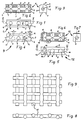
- FIG. 1 to 3 show basic, longitudinally sectioned (line II-II), elevation and side elevation of a component according to the invention
- FIG. 4 shows the ground plan of a further embodiment of the component according to the invention
- FIGS. 5 to 7 basic, longitudinally sectioned ( Line VI-VI) elevation and side elevation of a component according to the invention designed as a corner element
- FIGS. 8 and 9 ground plan and elevation of a concrete core poured into a wall of components according to FIG. 4
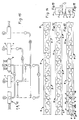
- FIGS. 10 and 11 ground plan and side elevation of a lowermost one 4
- FIGS. 12 and 13 show the plan and side elevation of a position to be arranged above it in a position shifted by 1/3 of the component length
- FIG. 14 shows the plan of another position, which is 2/3 compared to FIG the component length is offset
- FIG. 15 shows the diagram of a method for producing the components according to the invention.
- the component l according to the invention according to FIGS. 1 to 3 is essentially cuboid in shape and is delimited by two visible surfaces 2, two contact surfaces 3 and two abutment surfaces 4.
- a continuous horizontal channel 5 and three equally spaced vertically extending shafts 6 are formed.
- the channel 5 and the shafts 6 lie in a common plane and are connected to one another.
- the abutment surfaces 4 have tongue-and-groove profiles which - seen in plan view (FIG. 1) - are centrosymmetric with respect to the center of the component.
- a continuous groove 7 is formed on the lower (FIG. 3) support surface 3 and a tongue 8 corresponding to this is formed on the upper support surface 3.
- abutment surfaces 4 would then be located between the shafts 6.
- a component could also be made longer, i.e. with more shafts.
- Component 9 shown in FIG. 4 has some modifications compared to component 1.
- the shafts 6 are - seen in plan view - alternately offset in the direction of opposite sides of the channel 5 (which is not shown for clarity of the drawing); Shafts 6 and channel 5 are therefore not on the same level.
- the tongue-and-groove profiles of the abutting surfaces 4 are mirror-symmetrical with respect to the center of the component, so that the components 9 each have to be turned by 180 ° in relation to a vertical axis when they are joined laterally. This will the continuity of the mutual displacement of the shafts 6 is maintained.
- the groove 7 and the tongue 8 are no longer straight through. For reasons of clarity, only the groove 7 is shown in broken lines in FIG. 4.
- the design of the associated spring 8 can be seen in FIG. 10.
- the spring 8 with respect to its straight body of width b — has three sections 10 projecting in the direction of the visible surfaces, each of which is formed opposite the laterally offset shafts 6. These sections 10 can each have the same length, but are particularly dimensioned in the case shown. One of the three sections 10 (bottom left in FIG. 10) is longer than the other two by a predetermined amount s.
- the corresponding groove 7 (FIG. 4) - starting from the straight groove groove of width b - has three recesses 11, which in the simplest case can each have the same length. In the example shown, however - in analogy to the design of the spring 8 - one of the recesses 11 (top center in FIG. 4) is longer than the other two by the amount s.
- a further — ie fourth — recess 11 is provided (top right in FIG. 4), the length of which corresponds to the amount s and which directly adjoins one of the abutment surfaces 4.
- This particular embodiment of the groove 7 and the tongue 8 has the purpose of ensuring the compulsory positioning when the components 9 are layered one on top of the other so that the vertical shafts 6 are completely continuous in an erected wall.
- the component l2 shown in FIGS. 5 to 7 is a "corner element". It has only a single butt surface 4, but instead of the second butt surface a smooth end surface l3.
- the channel 5 opens into the shaft 6 adjacent to the end face l3.
- both the butting surface 4 and the two visible surface 2 have a simple profiling 14 Mistake.
- the groove 7 and the tongue 8 are somewhat modified compared to the embodiment according to FIGS. 1 to 3.
- the vertical shafts 6 are always aligned with the shafts 6 of the other components l or 9, the shafts 6 of the component l2 either have a larger diameter or are provided with an oval cross section at all; it can also happen that adjacent shafts 6 merge laterally into one another, ie form an elongated hole.
- FIGS. 8 and 9 illustrate a concrete core 15 which is obtained when components 9 according to FIG. 4 corresponding to FIGS. 10 to 14 are piled up to a wall and then poured out with concrete.
- components 9 lie next to one another, with every second one being turned by 180.degree. Relative to the previous one, with respect to a vertical axis.
- the mutual arrangement of the shafts 6 therefore extends homologously along the entire wall.
- the springs 8 on the upper support surfaces 3 of the components 9 are shown in FIG. 10, the grooves 7 on the lower support surfaces 3, however, are not shown.
- FIGS. L2 and l3 A component layer is shown in FIGS. L2 and l3, which can be placed on the position of FIG. 10 and is offset by l / 3 of the component length.
- FIGS. L2 and l3 A component layer is shown in FIGS. L2 and l3, which can be placed on the position of FIG. 10 and is offset by l / 3 of the component length.
- FIGS. 10 and 12 A component layer is shown in FIGS. L2 and l3, which can be placed on the position of FIG. 10 and is offset by l / 3 of the component length.
- FIG. 14 The meaningfulness of the specially dimensioned sections 10 and recesses 11 (FIG. 4) can be seen directly from FIGS. 10 and 12: they inevitably ensure a correct stacking of the components 9, with the aligned stacking of two components 9 also being excluded.
- the component position shown in FIG. 14 essentially corresponds to the position according to FIG. 2, but is compared to the component position according to FIG. 10 by 2/3 of
- the production method illustrated in Fig. L5 for the components l, 9 or l2 according to the invention comprises five work steps A, B, C, D, E in a production line, three of which - namely A, C and E - in fixed, equidistant processing positions and two - namely B and D - are carried out during the movement of the components along the production line.
- Two components located at a distance from adjacent fixed processing positions (A - C) are clamped together and pass through the production line in this clamping, which is symbolized by the position of the brackets I, II, III and I.
- Steps A and C or B and D are therefore carried out simultaneously - but on two different components.
- channel 5 is drilled out up to half the component length.
- step B the component detaches itself from the drill and then (step B) undergoes machining of its support surfaces 3 (bracket position II). Arrived in C, the shafts 6 are drilled and the abutting surfaces machined. Since the clamping is in bracket position III, it must be returned to the starting position I before the component is transported to D. In processing position C, the component located there is reclamped from one clamping end to the other. In step D, if necessary, the support surfaces 3 are finished, and when the component enters the processing position E, the second half of the channel 5 is finally opened drilled out on the drill. After returning the drill, the finished component is ultimately removed from the production line.
Landscapes
- Engineering & Computer Science (AREA)
- Structural Engineering (AREA)
- Chemical & Material Sciences (AREA)
- Architecture (AREA)
- Mechanical Engineering (AREA)
- Ceramic Engineering (AREA)
- Electromagnetism (AREA)
- Civil Engineering (AREA)
- Physics & Mathematics (AREA)
- Transition And Organic Metals Composition Catalysts For Addition Polymerization (AREA)
- Moulds, Cores, Or Mandrels (AREA)
- Joining Of Building Structures In Genera (AREA)
- Bearings For Parts Moving Linearly (AREA)
- Control Of Vending Devices And Auxiliary Devices For Vending Devices (AREA)
Claims (10)
- Elément de construction formé substantiellement comme une pierre de taille et présentant deux surfaces visibles, deux surfaces d'appui et au moins une surface d'about (2, 3 , 4) ainsi qu'au moins un canal horizontal (5) débouchant à la surface d'about (5), caractérisé en ce qu'à l'intérieur de l'élément de construction (1 ; 9 ; 12) au moins un trou vertical (6) en soi connu, s'étendant verticalement entre les surfaces d'appui (3), est formé, qui est relié au canal (5).
- Elément de construction selon la revendication 1, caractérisé en ce qu'une surface d'about (4) et une surface terminale lisse (13) en face de celle-ci sont prévues et que le canal (5) débouche dans un trou vertical (6) voisin de la surface terminale (13) (fig. 5 à 7).
- Elément de construction selon la revendication 1, caractérisé en ce que le perçage (6) - vu d'en haut - est latéralement décalé par rapport au canal (5) et que deux surfaces d'about (4) sont prévues qui présentent des profils qui - vus d'en haut - sont symétriques par rapport au milieu de l'élément de construction (fig. 4).
- Elément de construction selon la revendication 3, caractérisé en ce que trois trous verticals (6) équidistants sont prévus et qui - vus d'en haut - sont décalés en alternance dans le sens de côtés opposés du canal (5) (fig. 4).
- Elément de construction selon la revendication 4, caractérisé en ce que une rainure (7) - en soi connue - est formée sur une des deux surfaces d'appui (3) (l'inférieure) en direction longitudinale de l'élément de construction et, sur la surface d'appui opposée (supérieure) (3), un ressort correspondant (8), et que le ressort (8) présente trois sections (10) en saillie vers les surfaces visibles (2), sections qui sont chacune formées en face des trous verticals (6) décalés et que la rainure (7) est pourvue d'échancrures (11) correspondantes (fig. 4, 10).
- Elément de construction selon la revendication 5, caractérisé en ce que les sections (10) et les échancrures (11) ont la même longueur.
- Elément de construction selon la revendication 5, caractérisé en ce qu'une des trois sections (10) en saillie du ressort (8) est plus longue, d'une longueur prédéterminée (s), que les deux autres, qu'une des échancrures (11) de la rainure (7) est plus longue de la même longueur (s) et qu'une échancrure (11) supplémentaire (quatrième) est prévue dont la longueur correspond à la longueur prédéterminée (s) et qui avoisine directement l'une des surfaces d'about (4).
- Procédé pour la fabrication d'un élément de construction selon l'une des revendications 1 à 7, selon lequel certaines opérations individuelles sont exécutées l'une après l'autre dans une ligne de fabrication, caractérisé en ce que deux éléments de construction (1 ; 9 ; 12) sont montés en direction de la ligne de fabrication à distance l'un de l'autre et sont solidairement déplacés par intermittence le long de la ligne de fabrication, leur usinage se faisant aussi bien en mouvement qu'à l'arrêt.
- Procédé selon la revendication 8, caractérisé en ce que cinq opérations (A, B, C, D, E) sont prévues dont la première, troisième et cinquième (A, C, E) sont exécutées dans des positions d'usinage stationnaires et équidistantes, la deuxième et quatrième (B, D) en mouvement entre celles-là, et que les deux éléments de construction sont montés à distance de deux positions d'usinage stationnaires voisines (fig. 15).
- Procédé selon la revendication 9 pour la fabrication d'un élément de construction selon les revendications 3 à 7, caractérisé en ce que partant d'une pierre complète, le canal (5) est réalisé à moitié par la première opération, les surfaces d'appui (3) en partie pendant la deuxième opération, les trous verticaux (6) et les surfaces d'about (4) pendant la troisième opération, l'achèvement des surfaces d'about (3) pendant la quatrième opération, et la deuxième moitié du canal (5) pendant la cinquième opération.
Applications Claiming Priority (2)
| Application Number | Priority Date | Filing Date | Title |
|---|---|---|---|
| AT0247086A AT400457B (de) | 1986-09-15 | 1986-09-15 | Bauelement sowie verfahren zu dessen herstellung |
| AT2470/86 | 1986-09-15 |
Publications (3)
| Publication Number | Publication Date |
|---|---|
| EP0261101A2 EP0261101A2 (fr) | 1988-03-23 |
| EP0261101A3 EP0261101A3 (en) | 1990-05-23 |
| EP0261101B1 true EP0261101B1 (fr) | 1992-02-26 |
Family
ID=3534936
Family Applications (1)
| Application Number | Title | Priority Date | Filing Date |
|---|---|---|---|
| EP87890207A Expired - Lifetime EP0261101B1 (fr) | 1986-09-15 | 1987-09-09 | Elément de construction et son procédé de fabrication |
Country Status (3)
| Country | Link |
|---|---|
| EP (1) | EP0261101B1 (fr) |
| AT (2) | AT400457B (fr) |
| DE (1) | DE3776847D1 (fr) |
Cited By (1)
| Publication number | Priority date | Publication date | Assignee | Title |
|---|---|---|---|---|
| CN104631658A (zh) * | 2014-09-19 | 2015-05-20 | 昆明理工大学 | 一种适用于抗震设防高烈度区的土坯墙的施工方法及土坯 |
Families Citing this family (5)
| Publication number | Priority date | Publication date | Assignee | Title |
|---|---|---|---|---|
| IS1181A7 (is) * | 1960-09-22 | 1960-10-01 | Geir Kristj βnsson Hjalti | Hillujárn |
| FR2672327B1 (fr) * | 1991-02-04 | 1996-08-23 | Pierre Lagrega | Procede de construction de murs en beton arme, avec coffrage par blocs creux de polystyrene, et dispositif de fixation des grillages pour enduits. |
| DE9411494U1 (de) * | 1994-07-15 | 1995-11-30 | Lutz, Markus, 92353 Postbauer-Heng | Bauelement |
| DE4425057A1 (de) * | 1994-07-15 | 1996-01-18 | Markus Lutz | Bauelement |
| FR2977904B1 (fr) * | 2011-07-13 | 2015-01-02 | Dominique Rossi | Bloc de construction |
Family Cites Families (7)
| Publication number | Priority date | Publication date | Assignee | Title |
|---|---|---|---|---|
| FR579580A (fr) * | 1924-03-29 | 1924-10-20 | élément de construction | |
| US2882715A (en) * | 1956-03-14 | 1959-04-21 | Prec Building System Inc | Interlocking building block |
| DE1977164U (de) * | 1967-11-07 | 1968-01-18 | Kalksandsteinwerk Gumbmann Dai | Formgepresster kunststein, insbesondere kalksandstein. |
| AT340648B (de) * | 1975-08-19 | 1977-12-27 | Guttmann Gisela | Bauelement |
| DE7600792U1 (de) * | 1976-01-14 | 1976-05-26 | Hinse, Franz, 5400 Koblenz | Montageblock |
| DE2605079A1 (de) * | 1976-02-10 | 1977-08-11 | Wolfgang Wachter | Baustein fuer die ausbildung von jeglichem mauerwerk tragend und nicht tragend, fuer alle vorkommenden baumassnahmen im hoch- und tiefbau |
| DE8009618U1 (de) * | 1980-04-08 | 1980-08-07 | Greisel-Baustoff-Gmbh, 8359 Ortenburg | Gasbetonelement mit aussparungen |
-
1986
- 1986-09-15 AT AT0247086A patent/AT400457B/de not_active IP Right Cessation
-
1987
- 1987-09-09 DE DE8787890207T patent/DE3776847D1/de not_active Expired - Fee Related
- 1987-09-09 EP EP87890207A patent/EP0261101B1/fr not_active Expired - Lifetime
- 1987-09-09 AT AT87890207T patent/ATE72857T1/de not_active IP Right Cessation
Cited By (1)
| Publication number | Priority date | Publication date | Assignee | Title |
|---|---|---|---|---|
| CN104631658A (zh) * | 2014-09-19 | 2015-05-20 | 昆明理工大学 | 一种适用于抗震设防高烈度区的土坯墙的施工方法及土坯 |
Also Published As
| Publication number | Publication date |
|---|---|
| ATA247086A (de) | 1995-05-15 |
| DE3776847D1 (de) | 1992-04-02 |
| AT400457B (de) | 1996-01-25 |
| EP0261101A2 (fr) | 1988-03-23 |
| EP0261101A3 (en) | 1990-05-23 |
| ATE72857T1 (de) | 1992-03-15 |
Similar Documents
| Publication | Publication Date | Title |
|---|---|---|
| DE2459680C2 (de) | Verriegelungsblock | |
| DE2238660A1 (de) | Formschluessige fugenverbindung von plattenfoermigen bauelementen ohne gesonderte verbindungselemente | |
| DE2854853A1 (de) | Modulfoermiger baustein | |
| EP3489431A1 (fr) | Panneau | |
| DE2617510A1 (de) | Verfahren und vorrichtung zum herstellen von verkleidungen aus hartschaum | |
| DE1683009B2 (de) | Falttür mit mindestens zwei Tafeln | |
| AT400457B (de) | Bauelement sowie verfahren zu dessen herstellung | |
| DE3412441C2 (de) | Verfahren und Vorrichtung zur Bearbeitung von Fertigbauteilen | |
| DE60200851T2 (de) | Verfahren zur Herstellung von verstärkten Holzbalken und so erhaltener Holzbalken | |
| EP0738661B1 (fr) | Procèdè et dispositif pour la fabrication d'une pallette en matière plastique | |
| DE4317336C2 (de) | Verfahren zur Erstellung einer Wand | |
| DE2529337A1 (de) | Bauelemente aus gasbeton, verfahren zu ihrer herstellung sowie verwendung derselben zum errichten von mauern oder waenden | |
| DE1041672B (de) | Bausteinsatz | |
| DE8407334U1 (de) | Duebellochbohrmaschine | |
| DE2720042C3 (de) | Verbindung eines Längs- und Querrippen aufweisenden, vorgefertigten Stahlbetonbalkens und einer sich durch mehrere Stockwerke eines Gebäudes hindurch erstreckenden vorgefertigten Stahlbeton-Säule | |
| DE1802464A1 (de) | Baustein | |
| DE1813344C3 (de) | Vorrichtung zum Zusammenbau vorgefertigter Wandelemente | |
| EP1336701B1 (fr) | Panneau de plancher en tôle, acier ou similaire et procédé pour sa fabrication | |
| EP0432518B1 (fr) | Profil obtenu à partir de particules végétales moulées par pression | |
| DE2507634C3 (de) | Baustein mit Isolierschicht zum Errichten von Außenmauerwerk von Gebäuden | |
| EP0561390A1 (fr) | Bloc de construction pour installation électrique | |
| DE19517784A1 (de) | Bausatz und Verfahren zum Errichten von Trockenmauern mit wenigstens einseitig gebrochener Sichtfläche | |
| DE2510338A1 (de) | Fliessbandanordnung fuer die fertigung von bauelementen | |
| DE2614623A1 (de) | Bauelement, insbesondere baustein zur herstellung von mauern eines gebaeudes, sowie verfahren zur anfertigung des bauelementes | |
| DE2213072A1 (de) | Verfahren und Vorrichtung zur Herstellung von Baupaneelen |
Legal Events
| Date | Code | Title | Description |
|---|---|---|---|
| PUAI | Public reference made under article 153(3) epc to a published international application that has entered the european phase |
Free format text: ORIGINAL CODE: 0009012 |
|
| AK | Designated contracting states |
Kind code of ref document: A2 Designated state(s): AT BE CH DE ES FR GB GR IT LI LU NL SE |
|
| PUAL | Search report despatched |
Free format text: ORIGINAL CODE: 0009013 |
|
| AK | Designated contracting states |
Kind code of ref document: A3 Designated state(s): AT BE CH DE ES FR GB GR IT LI LU NL SE |
|
| 17P | Request for examination filed |
Effective date: 19900625 |
|
| 17Q | First examination report despatched |
Effective date: 19910726 |
|
| GRAA | (expected) grant |
Free format text: ORIGINAL CODE: 0009210 |
|
| AK | Designated contracting states |
Kind code of ref document: B1 Designated state(s): AT BE CH DE ES FR GB GR IT LI LU NL SE |
|
| PG25 | Lapsed in a contracting state [announced via postgrant information from national office to epo] |
Ref country code: NL Effective date: 19920226 Ref country code: GR Free format text: LAPSE BECAUSE OF FAILURE TO SUBMIT A TRANSLATION OF THE DESCRIPTION OR TO PAY THE FEE WITHIN THE PRESCRIBED TIME-LIMIT Effective date: 19920226 Ref country code: GB Effective date: 19920226 Ref country code: BE Effective date: 19920226 |
|
| REF | Corresponds to: |
Ref document number: 72857 Country of ref document: AT Date of ref document: 19920315 Kind code of ref document: T |
|
| REF | Corresponds to: |
Ref document number: 3776847 Country of ref document: DE Date of ref document: 19920402 |
|
| ITF | It: translation for a ep patent filed | ||
| PG25 | Lapsed in a contracting state [announced via postgrant information from national office to epo] |
Ref country code: ES Free format text: LAPSE BECAUSE OF FAILURE TO SUBMIT A TRANSLATION OF THE DESCRIPTION OR TO PAY THE FEE WITHIN THE PRESCRIBED TIME-LIMIT Effective date: 19920606 |
|
| ET | Fr: translation filed | ||
| NLV1 | Nl: lapsed or annulled due to failure to fulfill the requirements of art. 29p and 29m of the patents act | ||
| GBV | Gb: ep patent (uk) treated as always having been void in accordance with gb section 77(7)/1977 [no translation filed] | ||
| PG25 | Lapsed in a contracting state [announced via postgrant information from national office to epo] |
Ref country code: LU Free format text: LAPSE BECAUSE OF NON-PAYMENT OF DUE FEES Effective date: 19920930 |
|
| PLBE | No opposition filed within time limit |
Free format text: ORIGINAL CODE: 0009261 |
|
| STAA | Information on the status of an ep patent application or granted ep patent |
Free format text: STATUS: NO OPPOSITION FILED WITHIN TIME LIMIT |
|
| 26N | No opposition filed | ||
| PGFP | Annual fee paid to national office [announced via postgrant information from national office to epo] |
Ref country code: AT Payment date: 19940926 Year of fee payment: 8 |
|
| PGFP | Annual fee paid to national office [announced via postgrant information from national office to epo] |
Ref country code: FR Payment date: 19940929 Year of fee payment: 8 Ref country code: CH Payment date: 19940929 Year of fee payment: 8 |
|
| PGFP | Annual fee paid to national office [announced via postgrant information from national office to epo] |
Ref country code: SE Payment date: 19940930 Year of fee payment: 8 |
|
| EAL | Se: european patent in force in sweden |
Ref document number: 87890207.1 |
|
| PG25 | Lapsed in a contracting state [announced via postgrant information from national office to epo] |
Ref country code: AT Effective date: 19950909 |
|
| PG25 | Lapsed in a contracting state [announced via postgrant information from national office to epo] |
Ref country code: SE Effective date: 19950910 |
|
| PGFP | Annual fee paid to national office [announced via postgrant information from national office to epo] |
Ref country code: DE Payment date: 19950925 Year of fee payment: 9 |
|
| PG25 | Lapsed in a contracting state [announced via postgrant information from national office to epo] |
Ref country code: LI Effective date: 19950930 Ref country code: CH Effective date: 19950930 |
|
| REG | Reference to a national code |
Ref country code: CH Ref legal event code: PL |
|
| PG25 | Lapsed in a contracting state [announced via postgrant information from national office to epo] |
Ref country code: FR Effective date: 19960531 |
|
| EUG | Se: european patent has lapsed |
Ref document number: 87890207.1 |
|
| REG | Reference to a national code |
Ref country code: FR Ref legal event code: ST |
|
| PG25 | Lapsed in a contracting state [announced via postgrant information from national office to epo] |
Ref country code: DE Effective date: 19970603 |
|
| PG25 | Lapsed in a contracting state [announced via postgrant information from national office to epo] |
Ref country code: IT Free format text: LAPSE BECAUSE OF NON-PAYMENT OF DUE FEES;WARNING: LAPSES OF ITALIAN PATENTS WITH EFFECTIVE DATE BEFORE 2007 MAY HAVE OCCURRED AT ANY TIME BEFORE 2007. THE CORRECT EFFECTIVE DATE MAY BE DIFFERENT FROM THE ONE RECORDED. Effective date: 20050909 |