EP0261243A1 - Uhrenkonstruktion - Google Patents
Uhrenkonstruktion Download PDFInfo
- Publication number
- EP0261243A1 EP0261243A1 EP87900692A EP87900692A EP0261243A1 EP 0261243 A1 EP0261243 A1 EP 0261243A1 EP 87900692 A EP87900692 A EP 87900692A EP 87900692 A EP87900692 A EP 87900692A EP 0261243 A1 EP0261243 A1 EP 0261243A1
- Authority
- EP
- European Patent Office
- Prior art keywords
- wheel
- pinion
- gear train
- operating lever
- timepiece
- Prior art date
- Legal status (The legal status is an assumption and is not a legal conclusion. Google has not performed a legal analysis and makes no representation as to the accuracy of the status listed.)
- Granted
Links
- 238000010276 construction Methods 0.000 title abstract 3
- 239000000463 material Substances 0.000 claims abstract description 17
- 239000000758 substrate Substances 0.000 claims 2
- 238000004804 winding Methods 0.000 abstract description 51
- 230000015572 biosynthetic process Effects 0.000 abstract 1
- 238000010008 shearing Methods 0.000 description 6
- 239000007769 metal material Substances 0.000 description 4
- 230000002950 deficient Effects 0.000 description 2
- 238000000034 method Methods 0.000 description 2
- 229910000975 Carbon steel Inorganic materials 0.000 description 1
- 239000010962 carbon steel Substances 0.000 description 1
- 230000006378 damage Effects 0.000 description 1
- 239000013013 elastic material Substances 0.000 description 1
- 238000004519 manufacturing process Methods 0.000 description 1
- 238000000465 moulding Methods 0.000 description 1
Images





Classifications
-
- G—PHYSICS
- G04—HOROLOGY
- G04B—MECHANICALLY-DRIVEN CLOCKS OR WATCHES; MECHANICAL PARTS OF CLOCKS OR WATCHES IN GENERAL; TIME PIECES USING THE POSITION OF THE SUN, MOON OR STARS
- G04B27/00—Mechanical devices for setting the time indicating means
- G04B27/02—Mechanical devices for setting the time indicating means by making use of the winding means
- G04B27/04—Mechanical devices for setting the time indicating means by making use of the winding means with clutch wheel
-
- G—PHYSICS
- G04—HOROLOGY
- G04B—MECHANICALLY-DRIVEN CLOCKS OR WATCHES; MECHANICAL PARTS OF CLOCKS OR WATCHES IN GENERAL; TIME PIECES USING THE POSITION OF THE SUN, MOON OR STARS
- G04B27/00—Mechanical devices for setting the time indicating means
Definitions
- This invention relates to a time piece structure for time correcting and, in particular, to the structure of timepiece in which a gear train is formed of plastic materials.
- a gear train is formed of a center wheel having an elastic portion which is held and supported by a center wheel arbor.
- the center wheel When time is corrected, the center wheel is sheared and run idle through the center wheel arbor, thereby preventing trasnmission of rotation of the gear train from being transmitted to second hand (fourth wheel and pinion). Further, in a setting mechanism, a clutch wheel is moved by a winding stem, a setting lever, a yoke, and so on. The clutch wheel is fit into the members of gear train, and then time correcting is carried out by external operating materials.
- a conventional timepiece structure has the following problems since a sharing machanism utilizes the elastic portion of the center wheel in order to correct time.
- a clutching wheel When time is corrected, a clutching wheel must be engaged with a winding stem as an external control member at the angle cutting portions thereof to transmit the rotation. In the normal operation condition, a clutch wheel must be removed from the engagement with gear train members.
- This invention solves such problems and an object of the inventon is to obtain smooth time correcting mechanism without a shearing mechanism formed of wheels by removing one part of gear train members when time is corrected.
- Another object of the invention is to provide a timepiece improved in rationality by utilizing a plastic material for not only a gear train mechanism but also a setting mechanism instead of conventional requirement such as a setting lever, a yoke or the like.
- one part of gear train members is held and guided by the operating lever which is sequentially operated with the external control member.
- one part of gear train members is removed from engagement with a control lever.
- the clutch wheel is always engaged with the member of the gear train according to the setting structure of the clutch wheel made of plastic and external control member in which concave and convex portions are provided at the engaging portion of the clutch wheel. In the normal position, the clutch wheel is driven or rotated by the members of gear train.
- the clutch wheel is frictionally engaged with the convex portion and is operated with the external control members to be rotatable.
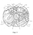
- Main plate 1 is a frame for a timepiece movement.
- Winding stem 2 is an external control member.
- Winding stem 2 has click portion 2-a which is engaged with elastic portion 3-a of plus terminal 3 of power source for positioning the winding stem. Further, frictional engagement convex portion 2-b is provided on the end portion of winding stem 2 which the clutch wheel 4 is put on, which is described later for description of time correcting.
- the winding stem is guided by main plate 1.
- Clutch wheel 4 is made of plastic materials and has a little steps between a center hole 4-a and wheel bottom 4-b.
- Minute wheel 8 is formed of plastic materials and has a wheel and a pinion.
- clutch wheel rim 4-c is loosely engaged with and guided by concave portion 1-a of main plate 1, thereby guiding the clutch wheel to the given position.
- central portion thereof 4-a and bottom portion thereof 4-b engaged with the minute wheel mentioned below are loosely engaged with and guided by winding stem axis 2-c and the convex portion 2-b of winding stem, respectively.
- the trunk of minute wheel is guided by a hole of main plate.
- the lower surface of minute wheel is guided by the projection of main plate and the clearance is determined by a gear train bridge mentioned below.
- the convex portion or projection of winding stem is closely fixed with interference in the center hole 4-a of the clutch wheel.
- the rim 4-c of the clutch wheel is contacted with the concave portion 1-a of main plate to guide the clutch wheel in the given position and to provide the destruction of the wheel of the clutch wheel.
- the reference numeral 5 stands for an operating lever.
- a gear train guide/hold portion supporting the lower pivot 6-a of the third wheel and pinion 6 are provided on operating lever 5, and the lever is rotated by the amount according to the movement of winding stem around axis 1-b, which is provided on main plate.
- a minute hand is mounted on the end portion of center wheel and pinion 7. The minute wheel is ordinally engaged with the center pinion and the gear portion 4-d of clutch wheel.
- An hour hand is mounted on the end portion of of hour wheel 9.
- a second hand is mounted on the end portion of the forth wheel and pinion 10.
- the gear train portion comprises the fifth wheel and pinion, rotor besides the above memebers.
- Gear train bridge 11 gudies the fifth wheel and pinion, the forth wheel and pinion, the third wheel and pinion and the upper pivot of minute wheel.
- the rotor is rotated by electric signal and the number of rotation is reduced by gear train.
- Each wheel operates as usual for analogically displaying seconds, minutes, and hours, and simalutaneously, the clutch wheel is engaged with the minute wheel to rotate the winding stem.
- condition of time correcting is explained.
- the operating lever is rotated around the guide axis, the holding portion for guiding the third lower pivot is moved, the third wheel and pinion results in tilting under support of the third upper pivot by the gear train bridge, and then the third pinion are removed from the engagement of the center wheel and pinion.
- the center hole of the clutch wheel is closely engaged in the convex portion of the winding stem.
- the rotation of the winding stem is transmitted from the clutch wheel to the minute wheel, from the minute wheel to the center wheel and pinion, and from the minute wheel to the hour wheel.
- time can be corrected as the second hand is fixed.
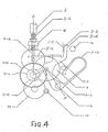
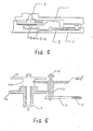
- Figs. 4 and 5 show the detailed structure of the operating lever 5.
- Fig. 4 is a plan view and
- Fig. 5 is a sectional view showing the portion of the winding stem which the operating lever is contacted with.
- the winding stem 2 is the external operating member. In the normal operation condition, the winding stem is loosely engaged with the clutch wheel 4. For time correcting, the winding stem is pulled out and is frictionally engaged with the clutch wheel, thereby transmitting the rotaion of the winding stem.
- the winding stem has concave and convex portion 2-a functioning as a click, which is engaged with elastic portion 3-a of battery plus terminal 3, thereby determining the position of winding stem 2.
- Operating lever 5 has the gear train guide/hold portion for lower pivot 6-a of the third wheel and pinion 6. Operating lever 5 is rotated and guided around axis 1-b on the main plate.
- the operating lever has elastic portion 5-a which the end portion 2-e of the winding stem is directly contacted.
- Point portion 5-b is directly contacted with the main plate, thereby positioning.
- Center wheel 7-a is engaged with the third pinion 6-b.
- Center wheel and pinion 7 comprise the above wheel and pinion 7-b, and the minute hand is mounted on the end portion thereof.
- Minute wheel 8 is always engaged with center pinion and the clutch wheel 4.
- Hour wheel 9 is engaged with the minute pinion and the hour hand is mounted on the end portion thereof (see Fig. 2).
- the gear train portion comprises the fifth wheel and pinion 14, rotor 15 besides the above members.
- the gear train bridge 11 guides the rotor, the fifth wheel and pinion, the forth wheel and pinion, the third wheel and pinion, and the upper pivot of the minute wheel.
- the lower pivot of each wheel and pinion except for the third wheel and pinion are guided by main plate 1.
- the rotor is rotated by electric signals, the number of rotation is reduced by gear train, and each wheel and pinion analogically displays seconds, minutes, and hours, thereby functioning as a conventional timepiece.
- the third wheel and pinion are tilted under the guide of the upper pivot 6-c by gear train bridge and the third pinion is removed from the engagement of the center wheel and pinion. It is because that the lower pivot thereof is guided and holded by the operating lever and that the operating lever is moved mentioned as above. Accompanied with the above motion, the clutch wheel is closely engaged with the convex portion 2-b of the winding stem. The rotation of the winding stem is transmitted from the minute wheel to center wheel and pinion and from the minute pinion to the hour wheel. Thus time correction for hour or minute can be completed with fixed seconds hand.
- This invention provides the new structure, in which the operating lever for guiding or holding the third wheel and pinion are improved in the stability of positioning.
- the amount of engagement between the center wheel and the third wheel is about 0.1 to 0.15 mm, and the operating lever must be always guided in the fixed position in order to obtain the stable efficiency of gear train.
- the operating lever is engaged with the end portion of the winding stem, and the edge 5-b of operating lever is directly contacted with main plate 1-c, thereby positioning.
- the operating lever directly contacted with the end portion of the winding stem has the elastic portion for absorbing the shift of the end portion of the winding stem.
- This elastical force is larger than that of U-shaped elastic portion 5-c.
- the operating lever according to this invention determines the position for engagement of the center wheel and pinion and the third wheel and pinion, using only the rigid portion thereof.
- the operation has the the elastic material at the moving portion of operating lever.
- Fig. 9 is a plan view showing the engagement condition of the wheel of center wheel and pinion 7 and the pinion of the third wheel and pinion.
- the engagement amount of the wheel and pinion for timepiece is about 0.2 mm in the wheel pitch, the wheel thickness is 0.09 mm, and the backlash is about 0.04 mm.
- the backlash of each wheel and pinion or the multiplation of erros in the configuration of gears causes the increase of the direction errors of hours hand, minute hands, and seconds hands, thereby the hands wrongly indicating the graduation of dial. Such a product is defective.
- Fig. 11 is a sectional view of Fig. 10 taken along A-B'.
- the example provides the clearance structure of-the upper pivot of third wheel and pinion 6, wherein the upper pivot is supported by a gear train bridge as a guide and the lower pivot is moved and tilted by an operating lever.
- the third wheel and pinion are tilted using the upper pivot 6-c, so that the wheel and pinion are removed from engagement. Therefore, if the clearance determining members are provided on a gear train having 0.005 to 0.1 mm necessary for wheel rotary movement, when the third wheel and pinion are tilted and moved, the clearance determining member and the upper portion of the wheel are touched together, thereby deforming the wheel or the upper pivot. As a result, the movement is defective.
- the clearance determining members should be provided one part of the circumference of the upper pivot, and not the all thereof. As shown in Figs. 10 and 11, the clearance determining members 11-a and 11-b for the gear train bridge should be provided along the center line, on which there are the least variation in the tilt of the third wheel and pinions, between the pivot center 6-c, and the rotary center 1-b of the operating lever.
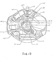
- main plate 1 is a frame for tiempiece.
- Winding stem 102 is an external operating member.
- Winding stem 102 has concave portion 102-a, convex portion 102-b and click portion 102-a.
- the concave portion 102-a is loosely engaged with the clutch wheel in the normal operating condition.
- the convex portion 102-b is frictionally engaged with the clutch wheel in the time correcting condition.
- the clutch wheel is positioned by the battery plus terminal.
- Clutch wheel 104 is loosely engaged with the winding stem and consists of plastic materials.
- Operating lever 105 is guided by axis 101-b which is provided on the main plate.
- the operating lever 105 has the portion 105-a which contacts with the end portion of winding stem as the above mentioned external operating member, 105-a and the elastic portion 105-b which rotates around the axis 101-b of the main plate and urges the operating lever into the anticrockwise direction, 105-b.
- Holding portion 105-c guides and holds the lower pivot of the third wheel and pinion 106. Further, the holding portion has projection for controlling the following fifth wheel and pinion.
- the third wheel and pinion 106 are made of plastic materials in which wheel and pinion are formed in one body. In the vicinity of the third wheel and pinion guide and the holding portion of the operating lever, the contact portion for contacting with the projection of the main plate is provided to reduce the variation of the accuracy in the engagement distance of the gear train.
- Center wheel and pinion 107 are made of plastic materials in which the wheel and pinion are formed of one body.
- Minute wheel is made of plastic wheel and pinion in which the wheel and the pinion is formed of one body.
- the wheel is always engaged with the above mentioned center pinion and the wheel of clutch wheel. Namely, the clutch wheel is driven by the minute wheel. In the normal operating condition, the clutch wheel rotates the winding stem.
- the forth wheel and pinion 110 are made of plastic materials in which wheel and pinion is formed of one body.
- the fifth wheel and pinion 114 is made of plastic materials in which the wheel and pinion is formed of one body in the same manner as the gear train.
- the fifth wheel and pinion is formed of one body with the control cam.
- Rotor 115 is made of plastic materials formed of a magnet by outserting and has a pinion.
- the gear train bridge guides the rotar, the fifth wheel and pinion, the forth wheel and pinion, the third wheel and pinion, the upper pinion of the minute wheel.
- the clutch wheel is frictionally engaged with the convex portion of the winding stem 102-b and interlocked with the movement of the winding stem. Namely, since the clutch wheel and the winding stem is closely fixed, the clutch wheel is elastically deformed, thereby obtaining the given constant torque.
- the rotation of the minute wheel is transmitted to the center wheel (and pinion), and the rotation of the pinion is transmitted to the clutch wheel to enable the time correction for hours, minutes and seconds.
- all the gear train members can be formed of plastic though the conventional timepiece uses metallic materials for a gear train and, more specifically, for the gear train members for time correcting mechanism. Accordingly, the manufacturing process can be simplified and the cost of members can reduced.
- the operating lever is directly moved by an external controlling member and it may be moved via anoter member. Further, the engagement is released in between the center wheel and pinion and the third pinion, and it can be released in between the third wheel and pinion and the forth pinion. Furthermore, in the description of the invention, the lower pivot is moved to release the engagement of the gear train, and the upper pivot may be moved simultaneously with the lower pivot to release the engagement of the gear train.
Landscapes
- Physics & Mathematics (AREA)
- General Physics & Mathematics (AREA)
- Electromechanical Clocks (AREA)
Applications Claiming Priority (10)
| Application Number | Priority Date | Filing Date | Title |
|---|---|---|---|
| JP4871186U JPS62160389U (de) | 1986-04-01 | 1986-04-01 | |
| JP4871286U JPS62160387U (de) | 1986-04-01 | 1986-04-01 | |
| JP48711/86U | 1986-04-01 | ||
| JP48712/86U | 1986-04-01 | ||
| JP100165/86 | 1986-04-30 | ||
| JP61100165A JPH0827360B2 (ja) | 1986-04-30 | 1986-04-30 | 指針式携帯時計の輪列 |
| JP1986088688U JPH0545995Y2 (de) | 1986-06-11 | 1986-06-11 | |
| JP88688/86U | 1986-06-11 | ||
| JP9607886U JPS632185U (de) | 1986-06-24 | 1986-06-24 | |
| JP96078/86U | 1986-06-24 |
Publications (3)
| Publication Number | Publication Date |
|---|---|
| EP0261243A1 true EP0261243A1 (de) | 1988-03-30 |
| EP0261243A4 EP0261243A4 (de) | 1988-07-14 |
| EP0261243B1 EP0261243B1 (de) | 1991-10-09 |
Family
ID=27522734
Family Applications (1)
| Application Number | Title | Priority Date | Filing Date |
|---|---|---|---|
| EP87900692A Expired - Lifetime EP0261243B1 (de) | 1986-04-01 | 1987-01-12 | Uhrenkonstruktion |
Country Status (3)
| Country | Link |
|---|---|
| US (1) | US4862434A (de) |
| EP (1) | EP0261243B1 (de) |
| WO (1) | WO1987006031A1 (de) |
Cited By (2)
| Publication number | Priority date | Publication date | Assignee | Title |
|---|---|---|---|---|
| EP1288743A1 (de) | 2001-08-30 | 2003-03-05 | Isa Swiss SA | Kupplungsvorrichtung für eine Uhr |
| EP2957964A2 (de) | 2014-06-19 | 2015-12-23 | Société anonyme de la Manufacture d'Horlogerie Audemars Piguet & Cie | Kippkupplung für uhren |
Families Citing this family (6)
| Publication number | Priority date | Publication date | Assignee | Title |
|---|---|---|---|---|
| CH682872B5 (fr) * | 1992-04-02 | 1994-06-15 | Ebauchesfabrik Eta Ag | Mouvement d'horlogerie comportant des moyens de guidage d'un organe de commande, tel qu'une tige. |
| CH691199A5 (fr) * | 1997-06-12 | 2001-05-15 | Ebauchesfabrik Eta Ag | Dispositif de débrayage dans un train d'engrenages de pièce d'horlogerie. |
| JP2006234440A (ja) * | 2005-02-22 | 2006-09-07 | Seiko Instruments Inc | 三番車外し構造及びこれを備えた時計 |
| ATE460689T1 (de) * | 2006-12-13 | 2010-03-15 | Longines Montres Comp D | Mechanismus für die zeigerstellung eines stundenanzeigers |
| US9671758B2 (en) * | 2013-02-23 | 2017-06-06 | Zhongyi WU | Quartz watch movement |
| CN110703581B (zh) * | 2019-10-24 | 2025-04-22 | 漳州铁拳电子科技有限公司 | 一种装配牢固的石英钟表的机芯结构 |
Family Cites Families (9)
| Publication number | Priority date | Publication date | Assignee | Title |
|---|---|---|---|---|
| CH328138A (fr) * | 1955-07-11 | 1958-02-28 | Watch Oris Co S A | Mécanisme de remontage et de mise à l'heure pour montre |
| DE6931554U (de) * | 1969-08-06 | 1970-01-29 | Licentia Gmbh | Getriebe, insbesondere uhrengetriebe mit kunststoffzahnraedern |
| JPS6032828B2 (ja) * | 1978-03-01 | 1985-07-30 | セイコ−光機株式会社 | 時計の秒規正装置 |
| JPS55152487A (en) * | 1979-05-16 | 1980-11-27 | Seiko Epson Corp | Crystal wrist watch |
| JPS618396Y2 (de) * | 1980-06-06 | 1986-03-14 | ||
| US4496246A (en) * | 1980-10-21 | 1985-01-29 | Kabushiki Kaisha Suwa Seikosha | Timepiece construction |
| JPS5849281A (ja) * | 1981-09-19 | 1983-03-23 | Ricoh Co Ltd | サ−マルプリンタ |
| JPS5849281U (ja) * | 1981-09-29 | 1983-04-02 | セイコーエプソン株式会社 | 時計の時刻修正機構 |
| JP3325953B2 (ja) * | 1993-05-19 | 2002-09-17 | スター精密株式会社 | シート保持装置 |
-
1987
- 1987-01-12 EP EP87900692A patent/EP0261243B1/de not_active Expired - Lifetime
- 1987-01-12 WO PCT/JP1987/000015 patent/WO1987006031A1/ja not_active Ceased
- 1987-01-12 US US07/138,904 patent/US4862434A/en not_active Expired - Lifetime
Cited By (4)
| Publication number | Priority date | Publication date | Assignee | Title |
|---|---|---|---|---|
| EP1288743A1 (de) | 2001-08-30 | 2003-03-05 | Isa Swiss SA | Kupplungsvorrichtung für eine Uhr |
| WO2003021364A3 (fr) * | 2001-08-30 | 2003-10-16 | Isa Swiss Sa | Dispositif d'embrayage pour piece d'horlogerie |
| EP2957964A2 (de) | 2014-06-19 | 2015-12-23 | Société anonyme de la Manufacture d'Horlogerie Audemars Piguet & Cie | Kippkupplung für uhren |
| US9411316B2 (en) | 2014-06-19 | 2016-08-09 | Société Anonyme de la Manufacture d'Horlogerie Audemars Piguet & Cie | Tilting coupling device for timepiece |
Also Published As
| Publication number | Publication date |
|---|---|
| EP0261243A4 (de) | 1988-07-14 |
| WO1987006031A1 (fr) | 1987-10-08 |
| US4862434A (en) | 1989-08-29 |
| EP0261243B1 (de) | 1991-10-09 |
Similar Documents
| Publication | Publication Date | Title |
|---|---|---|
| HK117297A (en) | Multi-time indicating analog watch | |
| US4862434A (en) | Timepiece structure | |
| US5903519A (en) | Calendar watch | |
| KR102092553B1 (ko) | 파워 리저브를 연장시키는 무브먼트 | |
| US6428201B1 (en) | Chronograph timepiece and lever device for timepiece | |
| CA2215545C (en) | Automatic watch | |
| US4259735A (en) | Timepiece movement with differential gear mechanism | |
| US6814483B2 (en) | Self-winding timepiece having train wheel setting apparatus | |
| US4845693A (en) | Apparatus for correcting a timepiece display | |
| US3731481A (en) | Time-setting device for electric timepiece | |
| US4244038A (en) | Watch having adjustable date and day indicators | |
| GB2026213A (en) | Date driving mechanism | |
| JP6787098B2 (ja) | 時計用ムーブメント、機械式時計および爪レバーの係合解除方法 | |
| US4636087A (en) | Gear train mechanism stop device of timepiece | |
| JPS6133473B2 (de) | ||
| JP2600158B2 (ja) | 電子時計 | |
| JP2021009169A (ja) | 時計用ムーブメントおよび機械式時計 | |
| KR940002272Y1 (ko) | 시계의 절환구조 | |
| EP1396765B1 (de) | Weltzeituhr mit Weckermechanismus | |
| JPH0568675B2 (de) | ||
| JP2617200B2 (ja) | 時計の指針修正機構 | |
| JP2020122670A (ja) | ゼネバ機構、カレンダ機構、時計用ムーブメント及び時計 | |
| JPH0827360B2 (ja) | 指針式携帯時計の輪列 | |
| JPS6020063Y2 (ja) | 時計の停止装置 | |
| JP2502676Y2 (ja) | 薄型時計用目安表示構造 |
Legal Events
| Date | Code | Title | Description |
|---|---|---|---|
| PUAI | Public reference made under article 153(3) epc to a published international application that has entered the european phase |
Free format text: ORIGINAL CODE: 0009012 |
|
| AK | Designated contracting states |
Kind code of ref document: A1 Designated state(s): CH DE FR GB LI |
|
| 17P | Request for examination filed |
Effective date: 19880302 |
|
| A4 | Supplementary search report drawn up and despatched |
Effective date: 19880714 |
|
| 17Q | First examination report despatched |
Effective date: 19900319 |
|
| RAP1 | Party data changed (applicant data changed or rights of an application transferred) |
Owner name: SEIKO EPSON CORPORATION |
|
| GRAA | (expected) grant |
Free format text: ORIGINAL CODE: 0009210 |
|
| AK | Designated contracting states |
Kind code of ref document: B1 Designated state(s): CH DE FR GB LI |
|
| REF | Corresponds to: |
Ref document number: 3773603 Country of ref document: DE Date of ref document: 19911114 |
|
| ET | Fr: translation filed | ||
| PLBE | No opposition filed within time limit |
Free format text: ORIGINAL CODE: 0009261 |
|
| STAA | Information on the status of an ep patent application or granted ep patent |
Free format text: STATUS: NO OPPOSITION FILED WITHIN TIME LIMIT |
|
| 26N | No opposition filed | ||
| REG | Reference to a national code |
Ref country code: GB Ref legal event code: IF02 |
|
| PGFP | Annual fee paid to national office [announced via postgrant information from national office to epo] |
Ref country code: DE Payment date: 20060105 Year of fee payment: 20 |
|
| PGFP | Annual fee paid to national office [announced via postgrant information from national office to epo] |
Ref country code: FR Payment date: 20060110 Year of fee payment: 20 |
|
| PGFP | Annual fee paid to national office [announced via postgrant information from national office to epo] |
Ref country code: GB Payment date: 20060111 Year of fee payment: 20 |
|
| PGFP | Annual fee paid to national office [announced via postgrant information from national office to epo] |
Ref country code: CH Payment date: 20060113 Year of fee payment: 20 |
|
| PG25 | Lapsed in a contracting state [announced via postgrant information from national office to epo] |
Ref country code: GB Free format text: LAPSE BECAUSE OF EXPIRATION OF PROTECTION Effective date: 20070111 |
|
| REG | Reference to a national code |
Ref country code: GB Ref legal event code: PE20 |
|
| REG | Reference to a national code |
Ref country code: CH Ref legal event code: PL |