EP0261278A1 - Heizapparat - Google Patents
Heizapparat Download PDFInfo
- Publication number
- EP0261278A1 EP0261278A1 EP86117893A EP86117893A EP0261278A1 EP 0261278 A1 EP0261278 A1 EP 0261278A1 EP 86117893 A EP86117893 A EP 86117893A EP 86117893 A EP86117893 A EP 86117893A EP 0261278 A1 EP0261278 A1 EP 0261278A1
- Authority
- EP
- European Patent Office
- Prior art keywords
- gas
- chamber
- heating
- work item
- heated
- Prior art date
- Legal status (The legal status is an assumption and is not a legal conclusion. Google has not performed a legal analysis and makes no representation as to the accuracy of the status listed.)
- Granted
Links
Images

Classifications
-
- B—PERFORMING OPERATIONS; TRANSPORTING
- B29—WORKING OF PLASTICS; WORKING OF SUBSTANCES IN A PLASTIC STATE IN GENERAL
- B29C—SHAPING OR JOINING OF PLASTICS; SHAPING OF MATERIAL IN A PLASTIC STATE, NOT OTHERWISE PROVIDED FOR; AFTER-TREATMENT OF THE SHAPED PRODUCTS, e.g. REPAIRING
- B29C33/00—Moulds or cores; Details thereof or accessories therefor
- B29C33/02—Moulds or cores; Details thereof or accessories therefor with incorporated heating or cooling means
- B29C33/04—Moulds or cores; Details thereof or accessories therefor with incorporated heating or cooling means using liquids, gas or steam
- B29C33/046—Moulds or cores; Details thereof or accessories therefor with incorporated heating or cooling means using liquids, gas or steam using gas
-
- B—PERFORMING OPERATIONS; TRANSPORTING
- B29—WORKING OF PLASTICS; WORKING OF SUBSTANCES IN A PLASTIC STATE IN GENERAL
- B29C—SHAPING OR JOINING OF PLASTICS; SHAPING OF MATERIAL IN A PLASTIC STATE, NOT OTHERWISE PROVIDED FOR; AFTER-TREATMENT OF THE SHAPED PRODUCTS, e.g. REPAIRING
- B29C41/00—Shaping by coating a mould, core or other substrate, i.e. by depositing material and stripping-off the shaped article; Apparatus therefor
- B29C41/34—Component parts, details or accessories; Auxiliary operations
- B29C41/46—Heating or cooling
-
- C—CHEMISTRY; METALLURGY
- C21—METALLURGY OF IRON
- C21D—MODIFYING THE PHYSICAL STRUCTURE OF FERROUS METALS; GENERAL DEVICES FOR HEAT TREATMENT OF FERROUS OR NON-FERROUS METALS OR ALLOYS; MAKING METAL MALLEABLE, e.g. BY DECARBURISATION OR TEMPERING
- C21D1/00—General methods or devices for heat treatment, e.g. annealing, hardening, quenching or tempering
- C21D1/74—Methods of treatment in inert gas, controlled atmosphere, vacuum or pulverulent material
- C21D1/767—Methods of treatment in inert gas, controlled atmosphere, vacuum or pulverulent material with forced gas circulation; Reheating thereof
-
- F—MECHANICAL ENGINEERING; LIGHTING; HEATING; WEAPONS; BLASTING
- F26—DRYING
- F26B—DRYING SOLID MATERIALS OR OBJECTS BY REMOVING LIQUID THEREFROM
- F26B21/00—Arrangements for supplying or controlling air or other gases for drying solid materials or objects
- F26B21/50—Ducting arrangements from the source of air or other gases to the materials or objects being dried
-
- F—MECHANICAL ENGINEERING; LIGHTING; HEATING; WEAPONS; BLASTING
- F27—FURNACES; KILNS; OVENS; RETORTS
- F27B—FURNACES, KILNS, OVENS OR RETORTS IN GENERAL; OPEN SINTERING OR LIKE APPARATUS
- F27B5/00—Muffle furnaces; Retort furnaces; Other furnaces in which the charge is held completely isolated
- F27B5/06—Details, accessories or equipment specially adapted for furnaces of these types
- F27B5/16—Arrangements of air or gas supply devices
-
- F—MECHANICAL ENGINEERING; LIGHTING; HEATING; WEAPONS; BLASTING
- F27—FURNACES; KILNS; OVENS; RETORTS
- F27B—FURNACES, KILNS, OVENS OR RETORTS IN GENERAL; OPEN SINTERING OR LIKE APPARATUS
- F27B9/00—Furnaces through which the charge is moved mechanically, e.g. of tunnel type; Similar furnaces in which the charge moves by gravity
- F27B9/06—Furnaces through which the charge is moved mechanically, e.g. of tunnel type; Similar furnaces in which the charge moves by gravity heated without contact between combustion gases and charge; electrically heated
- F27B9/10—Furnaces through which the charge is moved mechanically, e.g. of tunnel type; Similar furnaces in which the charge moves by gravity heated without contact between combustion gases and charge; electrically heated heated by hot air or gas
-
- F—MECHANICAL ENGINEERING; LIGHTING; HEATING; WEAPONS; BLASTING
- F27—FURNACES; KILNS; OVENS; RETORTS
- F27D—DETAILS OR ACCESSORIES OF FURNACES, KILNS, OVENS OR RETORTS, IN SO FAR AS THEY ARE OF KINDS OCCURRING IN MORE THAN ONE KIND OF FURNACE
- F27D7/00—Forming, maintaining or circulating atmospheres in heating chambers
- F27D7/04—Circulating atmospheres by mechanical means
-
- B—PERFORMING OPERATIONS; TRANSPORTING
- B29—WORKING OF PLASTICS; WORKING OF SUBSTANCES IN A PLASTIC STATE IN GENERAL
- B29C—SHAPING OR JOINING OF PLASTICS; SHAPING OF MATERIAL IN A PLASTIC STATE, NOT OTHERWISE PROVIDED FOR; AFTER-TREATMENT OF THE SHAPED PRODUCTS, e.g. REPAIRING
- B29C35/00—Heating, cooling or curing, e.g. crosslinking or vulcanising; Apparatus therefor
- B29C35/02—Heating or curing, e.g. crosslinking or vulcanizing during moulding, e.g. in a mould
- B29C35/04—Heating or curing, e.g. crosslinking or vulcanizing during moulding, e.g. in a mould using liquids, gas or steam
- B29C35/045—Heating or curing, e.g. crosslinking or vulcanizing during moulding, e.g. in a mould using liquids, gas or steam using gas or flames
Definitions
- This invention relates to an apparatus for heat treating a work item by a hot blast.
- the heating apparatus of this invention may generally be applied to, for example, a slush molding process.
- heating apparatus which use the hot blast as a heating medium.
- One is of an internal heating type in which a heat source is disposed inside the heating chamber of a furnace, and the other is of an external heating type in which the hot blast is fed into the working space from the outside heat source.
- a burner or a heater is normally employed as the heat source for both types.
- Some of such conventional heating apparatus are provided with a guide member to lead a hot gas to a particular direction or a fan to stir the hot gas within the working space in order to make the heating step efficient as much as possible. Also, some are provided with an impeller or a fan which can blow the hot blast against a given portion of the work item more strongly than the rest. These conventional heating apparatus, however, did not allow a spot heating of any particular portion of the work item so that it may be heated at comparatively a faster speed than the remainder. Thus, when the work item has a complicated shape or a certain portion thereof is thicker than the rest, difference in heat capacity becomes large, resulting in a poor thermal efficiency.
- the present invention contemplates dissolving the abovementioned drawbacks of the conventional apparatus.
- the extent of such control may vary in accordance, with shape, material, type of the work item.
- the heating apparatus of the present invention comprises a furnace body having a chamber to maintain a heated gas like air, a means for holding a work item at a given position in the furnace chamber, at least one compressed gas supplying pipe introduced in the furnace chamber, a single or a plurality of nozzles to spout the compressed gas and lead it in the particular direction under an action of the gas spouting energy.
- the compressed gas supplying pipe characteristically includes at least one spot heating device for spouting the compressed gas from the nozzle.
- the heating medium for high temperature is directed along a predetermined flow path by making use of the gas spouting energy from the nozzle so that any particular portion of the work item can be heated more efficiently than the rest.
- the heating apparatus of the present invention mainly comprises a furnace body, a means for holding the work item, at least a compressed gas supplying pipe, and a spot heating device associated with the compressed gas supplying pipe.
- the furnace body includes a furnace chamber which is the heart of the heating apparatus, and retains the heated gas to heat the work item to be introduced therein.
- the furnace can be in the shape of box, cell, vertical and the like. This shape of the furnace can be selected optionally in accordance with shape, material or the like of the work item to be processed.
- the apparatus of the present invention can be either inner or external one.
- the furnace body is constructed to allow the hot blast and radiant heat to render heat energy to the work item in the furnace chamber.
- the hot blast may be circulated such that the gas cooled down may be heated again during the circulation.
- a separate heated gas supplying section be disposed in combination with the furnace body.
- the separate heated gas supplying section can be constituted by a heat source and a duct which communicates the heat source with the furnace body.
- the heated gas emitted by the heat source be circulated through the duct.
- This circulation can be made such that after the heated gas has been transferred to the furnace chamber of the furnace body, an exhaust gas cooled down be reentered into the heat source to be heated again for recirculation.
- the means for holding the work item functions to support the work item at a predetermined position in the furnace chamber.
- This holding means can be any means as long as it holds the work item at a proper position.
- it may be of the type in which the entry and exit of the work item is made one by one to and from the furnace chamber of the furnace body.
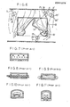
- the holding means may comprise a plurality of rollers on which work items are conveyed in sequence, or as shown in Fig.8, the holding means may be in the form of rails. That is, the holding means may comprise conveyer rollers as shown in Fig.7, or rails as shown in Fig.8, or endless belt means as shown in Fig.9, or a combination of guide rails and trucks as shown in Figs.10 and 11.
- the furnace body and the holding means be provided with a sensor to detect type or model of the work item.
- the compressed gas supplying pipe transfers a compressed gas to the furnace chamber and guides it in the heating chamber in the predetermined direction so that the particular portion of the work item can be heated efficiently.
- a plurality of pipes are provided along the ceiling, the wall, the floor or the like within the furnace chamber.
- This compressed gas supplying pipe communicates with a compressor generating the compressed gas.
- the compressor may be a usual air compressor, and the compressed gas may be air or gas with a considerably reduced temperature like the gas exhausted from the furnace body.
- air it is preferable that air be used because it does not exert any adverse affection on the compressor. In this case, there is no need that air is a heated one with high temperature. However, it is rather desirable that the compressed gas itself has high temperature. Accordingly, it is possbile to use the compressed gas which may be heated for high temperature while it is retained in the pipe.
- the spot heating devices comprise nozzles which communicate with the compressed gas supplying pipe to spout the compressed gas. It is desirable that the spot heating device comprise a nozzle and a guide tube to lead the spouted gas in the given direction.
- the connection between the spot heating device and the compressed gas supplying pipe is made by means of a flexible tube such that position or direction of the nozzle may be changed freely.
- At least one spot heating device is provided on the compressed gas supplying pipe. Namely, some of the pipes may have only one spot heating device, and some are provided with a plurality of spot heating devices.
- the function of the spot heating device is similar to that of a known aspirater.
- the spouting energy of the compressed gas is used to orient the surrounding heated gas to a given direction, whereby thus oriented heated gas blows against the particular portion of the work item.
- the spot heating device of the present invention blows off the boundary region by means of hot gas enegized to flow in the constant direction, and supplies sequentically a renewed heated gas with high temperature to the predermined portion-of the work item.
- Electromagnetic valves may be employed for control means, but in view of their durability, they should be provided at a location on the compressed gas supplying pipe where a thermal impact is as little as possible.
- the heating mode can be adjusted to type of work items so that they are heated with high efficiency.
- the work item to be processed is not limited to any particular one, but especially, the heating apparatus of the present invention can be used in a heating step of a slush molding process. Especially, if a provision is made such that a wide variety of slush molds each having a complicated and different shape can be used, that would suffice the purpose of the present invention.
- identification mark or configuration for example, a protrusion diposed on a particular portion
- identification mark or configuration may be detected by a sensor positioned on the furnace body or assembled together with the work item holding means. Then, based on the result of such mark or configuration detection, electromagnetic means of selected compressed gas supplying pipe may be caused to control one or a plurality of spot heating devices attached to the pipe so that the heated gas is spouted all at once.
- a microcomputer, a program controller and the like be used to control a part or the entire of heating operation such as heating hours, gas supplying hours, transfer of work items, etc. in the work space of the furnace body.
- the work item when introduced into the furnace chamber, the work item is held by the holding means and heated in all by the heated gas retained in the heating chamber.
- a blast of a hot gas spouted from the selected spot heating device is directed to the predetermined portion of the work item in order to heat it rapidly, resulting in high efficient heating of such given portion.
- a furnace of external heating type mainly comprises a furnace body 1, a hot gas supplying source 2, a rail-shaped holding device 3, and a compressed gas supplying pipe 5 with spot heating devices 4.
- the furnace body 1 is fixed on a base 11 and has a box-shape, measuring 2.6 m (Length), 2.8 m (Width), 3.5 m (Height).
- Adjacent to the entry of the furnace body 1 is provided a preheating chamber 14.
- a door 12 at the entrance to the preheating chamber 14 and a door .13 at the entrance to the furnace body 1 are provided respectively.
- the heated gas supplying source (not shown) comprises a combustion chamber 21 and an air blast portion 22.
- the combustion chamber 21 has a burner (now shown) in the center, and receives a supply of fresh air from the rear of the burner.
- the gas cooled down in the low temperature gas chamber 16 reenters into the combustion chamber 21 through the inlet on its peripheral portion to be mixed with combustion gas with high temperature.
- a fan Inside the air blast portion 22 at the other end of the combustion chamber 21 is incorporated a fan (not shown) which functions to transfer the mixed gas to a main air transfer duct 123.
- a main exhaust gas transfer duct 232 is connected between the low temperature gas chamber 16 of the furnace body 1 and the combustion chamber 21.
- Each of these sub ducts 233 and 234 is connected to the preheating chamber 14.
- a plurality of compressed gas supplying pipes 5 are arranged side by side in a group at the upper part of the heating chamber 17.
- One end of each of the pipes 5 is connected to a bypass (not shown) which communicates with a trunk gas pipe (not shown) which in turn is coupled with an air compressor (not shown).
- Each of the compressed gas supplying pipes 5 is provided with several spot heating devices 4 which are controlled in a group by the central means mentioned above.
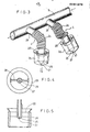
- Each of the spot heating devices 4 is constituted by a flexible bellow 24 which communicates with the compressed air supplying pipe 5 through a connecting pipe 29, a nozzle 25 attached to the forward end of the bellow 24 and a tubular guide member 26 surrounding the nozzle 25.
- the nozzle 25 has, at its tip end, a pore 27 through which the compressed gas is spouted.
- the tubular guide member 26 is welded to the peripheral portion of the nozzle 25 through a rib 28.
- the tubular guide member 26 is integral with the nozzle 25.
- the means for holding the work item 3 is a chain-like endless driving device on which a slush mold 31 is placed at a predermined interval.
- the endless driving device is intermittently driven. Namely, it stops for some seconds, then moves by a constant distance (some cm) and repeats the operation.
- the furnace including the preheating chamber 14 can accommodate three work items (slush mold) at a time. At this point, it is to be appreciated that the preheating chamber 14 has no spot heating devices 4.
- the heating chamber 17 is constituted to accommodate two work items. The heating is conducted in two steps. For each of the heating steps, the spot heating device 4 is operatively arranged in the heating chamber 17.
- a sensor detects the type of the slush mold at the entrance to the heating chamber 17, and outputs a signal to supply a compressed gas to a selected compressed gas supplying pipe which is equipped with spot heating devices suitable to heat the supplied slush mold.
- Fig.6 shows a vertical-sectional view of work item to be heated by the heating apparatus of the present invention.
- the work item comprises a slush mold 31 and a frame means 32.
- the slush mold 31 is made from nickel with a thickness of about 4 mm and has relatively a complicated shape.
- the marginal portion of opened side of this slush mold 31 is provided with a flange-like member.
- the frame means 32 has a frame at a position corresponding to each edge of the rectangular parallel- piped.
- the work item receives the hot blast from the upperpart (see Fig.6) and is heated from the reverse side.
- the frame means 32 does not interfere in any way the blow of the hot blast, so that the slush mold 31 can directly be heated by the hot blast.
- the general flow of heated gas is as shown in the solid line in Fig.6.
- a nozzle 25 oriented to the convex portion of the slush mold 31 spouts compressed air, thus allowing the hot blast to be guided in the direction of dotted line in Fig.6. In this manner, the hot blast is rendered concentrically to the convex portion of the slush mold 31 for heating it efficiently.
- a guide member 37 attached to the frame means 32 is jointly used to direct the blow of the heated gas supplied from the compressed gas supplying pipe 5', nozzle 25' and tubular guide member 26'.
- the entry and exit doors of the furnace are opened every 1.5 - 2.0 minutes and the work items are introduced into the furnace chamber by the synchronous movement of the conveyor belt by approx. 130 cm. After finishing two heating steps, the work item is sent out of the furnace.
- both entrance and exit doors are closed in synchronism, the heated gas is supplied to the spot heating device 4 from the selected compressed gas supplying pipe 5 and the heated gas is spouted from the nozzle 25.
- the gas spouting energy is used to lead the flow of surrounding heated, gas to the particular target portion to heat it locally.
- the heated gas produced by the burner of the hot gas supplying section 2 is mixed with the exhaused gas (cooled down) transferred from the furnace body 1. Then the mixed gas is conveyed to the high temperature gas chamber 15 through the main air transfer duct 123.
- the gas entered in the high temperature gas chamber 15 flows downward to the heating chamber 17 and thereafter transferred to the low temperature gas chamber 16 at the bottom.
- the exhausted gas from the low temperature gas chamber 16 passes through the main exhaust gas duct 232 and reenters into the combustion chamber 21.
- the heated gas is circulated.
- Some amount of hot gas leaks from doors 12, 13 of the furnace and the like.
- Fresh air corresponding to the leaked amount of gas is supplied to the furnace to promote combustion by the burner.
- the heating apparatus of the present invention can heat the entire configurations of the work item by a blast of hot gas.
- the spot heating device is provided, the particular portion of the work item can be heated efficiently. Accordingly, the heating apparatus of the present invention is suitable to heat a work item of which particular portion need to be heated by high temperature or a work item for which uniform heating is not available in a normal furnace because of its complicated shape and uneven thickness.
- the compressed gas necessary for spot heating is not required to be heated, a normal compressed pump or air compressor can be used, without any necessity of special equipment.
- the heating apparatus of the present invention is particularly intended for practical use.
Landscapes
- Engineering & Computer Science (AREA)
- Mechanical Engineering (AREA)
- General Engineering & Computer Science (AREA)
- Chemical & Material Sciences (AREA)
- Combustion & Propulsion (AREA)
- Physics & Mathematics (AREA)
- Thermal Sciences (AREA)
- Crystallography & Structural Chemistry (AREA)
- Materials Engineering (AREA)
- Metallurgy (AREA)
- Organic Chemistry (AREA)
- Moulding By Coating Moulds (AREA)
- Tunnel Furnaces (AREA)
- Furnace Details (AREA)
Applications Claiming Priority (2)
| Application Number | Priority Date | Filing Date | Title |
|---|---|---|---|
| JP216141/86 | 1986-09-13 | ||
| JP61216141A JPS6373085A (ja) | 1986-09-13 | 1986-09-13 | 加熱装置 |
Publications (2)
| Publication Number | Publication Date |
|---|---|
| EP0261278A1 true EP0261278A1 (de) | 1988-03-30 |
| EP0261278B1 EP0261278B1 (de) | 1992-03-18 |
Family
ID=16683915
Family Applications (1)
| Application Number | Title | Priority Date | Filing Date |
|---|---|---|---|
| EP86117893A Expired EP0261278B1 (de) | 1986-09-13 | 1986-12-22 | Heizapparat |
Country Status (3)
| Country | Link |
|---|---|
| EP (1) | EP0261278B1 (de) |
| JP (1) | JPS6373085A (de) |
| DE (1) | DE3684475D1 (de) |
Cited By (12)
| Publication number | Priority date | Publication date | Assignee | Title |
|---|---|---|---|---|
| FR2630199A1 (fr) * | 1988-04-19 | 1989-10-20 | Stein Heurtey | Installation de traitement thermique par convection, notamment de pieces destinees a l'industrie automobile |
| EP0568179A1 (de) * | 1992-04-30 | 1993-11-03 | Imperial Chemical Industries Plc | Lackierkabine und Verfahren zur Beschleunigung der Verdampfung des Verdünners aus einer Beschichtung auf einer Plattenoberfläche |
| EP0690279A1 (de) * | 1994-06-28 | 1996-01-03 | Ransburg Corporation | Farbspritz- und -Härtungskabine |
| EP0678719A3 (de) * | 1994-04-21 | 1996-03-20 | Rota Cab Bv | Vorrichtung und Verfahren zur Trocknung von Oberflächen mit wässrigen Farben. |
| WO1996008686A1 (en) * | 1994-09-15 | 1996-03-21 | Edwin Trisk Systems Limited | Apparatus for drying a painted surface |
| WO1996008705A1 (en) * | 1994-09-13 | 1996-03-21 | Teledyne Industries, Inc. | Miniature silicon based thermal vacuum sensor and method of measuring vacuum pressures |
| EP0770691A1 (de) * | 1995-10-19 | 1997-05-02 | Peter Helmut Dipl.-Ing. Ebner | Anlage zur Wärmebehandlung von metallischem Glühgut |
| EP0695615A3 (de) * | 1994-08-01 | 1998-01-21 | Amelia Gomez Barragan | Tunnelofen zum Trocknen und Vulkanisieren von Gummiprofilen |
| WO2013021164A3 (en) * | 2011-08-08 | 2013-04-18 | Surface Generation Limited | Tool temperature control |
| CN107101497A (zh) * | 2017-06-19 | 2017-08-29 | 中南大学 | 一种高低温双体真空热压烧结炉 |
| EP3779340A1 (de) * | 2019-08-13 | 2021-02-17 | Luca Rogai | Tragbare trocknungsvorrichtung für lackieranlagen |
| CN116533430A (zh) * | 2023-05-08 | 2023-08-04 | 浙江德龙科技有限公司 | 一种自动流延机 |
Families Citing this family (1)
| Publication number | Priority date | Publication date | Assignee | Title |
|---|---|---|---|---|
| CN102706172A (zh) * | 2012-01-16 | 2012-10-03 | 苏州工业园区姑苏科技有限公司 | 一种焙烧炉炉气循环装置 |
Citations (6)
| Publication number | Priority date | Publication date | Assignee | Title |
|---|---|---|---|---|
| FR2099954A5 (de) * | 1970-06-26 | 1972-03-17 | Kleindienst & Co | |
| GB1274358A (en) * | 1970-02-06 | 1972-05-17 | Carrier Engineering Co Ltd | A tunnel in which articles are treated by jets of air |
| FR2436350A1 (fr) * | 1978-09-13 | 1980-04-11 | Degussa | Four a vide avec dispositif de refroidissement au gaz |
| FR2476293A1 (fr) * | 1980-02-14 | 1981-08-21 | Fours Indls Cie | Four de chauffage par convection |
| DE3321554C1 (de) * | 1982-07-16 | 1984-02-16 | Ipsen Industries International Gmbh, 4190 Kleve | Industrieofen zur Wärmebehandlung metallischer Werkstücke |
| GB2152199A (en) * | 1983-12-23 | 1985-07-31 | Ipsen Ind Int Gmbh | Industrial furnace |
Family Cites Families (2)
| Publication number | Priority date | Publication date | Assignee | Title |
|---|---|---|---|---|
| US4135702A (en) * | 1976-10-29 | 1979-01-23 | Venetta, Inc. | Method and apparatus for preheating scrap |
| JPS607814U (ja) * | 1983-06-28 | 1985-01-19 | 丸山 昌明 | 弁付き湯たんぽ |
-
1986
- 1986-09-13 JP JP61216141A patent/JPS6373085A/ja active Granted
- 1986-12-22 EP EP86117893A patent/EP0261278B1/de not_active Expired
- 1986-12-22 DE DE8686117893T patent/DE3684475D1/de not_active Expired - Fee Related
Patent Citations (6)
| Publication number | Priority date | Publication date | Assignee | Title |
|---|---|---|---|---|
| GB1274358A (en) * | 1970-02-06 | 1972-05-17 | Carrier Engineering Co Ltd | A tunnel in which articles are treated by jets of air |
| FR2099954A5 (de) * | 1970-06-26 | 1972-03-17 | Kleindienst & Co | |
| FR2436350A1 (fr) * | 1978-09-13 | 1980-04-11 | Degussa | Four a vide avec dispositif de refroidissement au gaz |
| FR2476293A1 (fr) * | 1980-02-14 | 1981-08-21 | Fours Indls Cie | Four de chauffage par convection |
| DE3321554C1 (de) * | 1982-07-16 | 1984-02-16 | Ipsen Industries International Gmbh, 4190 Kleve | Industrieofen zur Wärmebehandlung metallischer Werkstücke |
| GB2152199A (en) * | 1983-12-23 | 1985-07-31 | Ipsen Ind Int Gmbh | Industrial furnace |
Cited By (16)
| Publication number | Priority date | Publication date | Assignee | Title |
|---|---|---|---|---|
| FR2630199A1 (fr) * | 1988-04-19 | 1989-10-20 | Stein Heurtey | Installation de traitement thermique par convection, notamment de pieces destinees a l'industrie automobile |
| EP0568179A1 (de) * | 1992-04-30 | 1993-11-03 | Imperial Chemical Industries Plc | Lackierkabine und Verfahren zur Beschleunigung der Verdampfung des Verdünners aus einer Beschichtung auf einer Plattenoberfläche |
| US5397606A (en) * | 1992-04-30 | 1995-03-14 | Imperial Chemical Industries Plc | Enclosure for painting and a method of enforcing evaporation from a coating on a panel surface |
| EP0678719A3 (de) * | 1994-04-21 | 1996-03-20 | Rota Cab Bv | Vorrichtung und Verfahren zur Trocknung von Oberflächen mit wässrigen Farben. |
| EP0690279A1 (de) * | 1994-06-28 | 1996-01-03 | Ransburg Corporation | Farbspritz- und -Härtungskabine |
| EP0695615A3 (de) * | 1994-08-01 | 1998-01-21 | Amelia Gomez Barragan | Tunnelofen zum Trocknen und Vulkanisieren von Gummiprofilen |
| ES2113263A1 (es) * | 1994-08-01 | 1998-04-16 | Barragan Amelia Gomez | Horno longitudinal continuo para secados y vulcanizados de perfiles de caucho. |
| WO1996008705A1 (en) * | 1994-09-13 | 1996-03-21 | Teledyne Industries, Inc. | Miniature silicon based thermal vacuum sensor and method of measuring vacuum pressures |
| WO1996008686A1 (en) * | 1994-09-15 | 1996-03-21 | Edwin Trisk Systems Limited | Apparatus for drying a painted surface |
| EP0770691A1 (de) * | 1995-10-19 | 1997-05-02 | Peter Helmut Dipl.-Ing. Ebner | Anlage zur Wärmebehandlung von metallischem Glühgut |
| WO2013021164A3 (en) * | 2011-08-08 | 2013-04-18 | Surface Generation Limited | Tool temperature control |
| US10471494B2 (en) | 2011-08-08 | 2019-11-12 | Surface Generation Limited | Tool temperature control |
| CN107101497A (zh) * | 2017-06-19 | 2017-08-29 | 中南大学 | 一种高低温双体真空热压烧结炉 |
| EP3779340A1 (de) * | 2019-08-13 | 2021-02-17 | Luca Rogai | Tragbare trocknungsvorrichtung für lackieranlagen |
| CN116533430A (zh) * | 2023-05-08 | 2023-08-04 | 浙江德龙科技有限公司 | 一种自动流延机 |
| CN116533430B (zh) * | 2023-05-08 | 2024-01-30 | 浙江德龙科技有限公司 | 一种自动流延机 |
Also Published As
| Publication number | Publication date |
|---|---|
| EP0261278B1 (de) | 1992-03-18 |
| JPS6373085A (ja) | 1988-04-02 |
| DE3684475D1 (de) | 1992-04-23 |
| JPH0252197B2 (de) | 1990-11-09 |
Similar Documents
| Publication | Publication Date | Title |
|---|---|---|
| EP0261278A1 (de) | Heizapparat | |
| KR100411645B1 (ko) | 인공 기후실 및 인공 기후 장치의 온도 제어 방법 | |
| EP0370313B1 (de) | Wärmeausgleich in einem Glasscheiben-Biegeofen und Biegeofen | |
| US4354549A (en) | Induced circulation oven or cooler | |
| US6776008B1 (en) | Method and apparatus for heating glass | |
| JP2004269242A (ja) | コンベヤーオーブン | |
| US4481025A (en) | Glass annealing lehr | |
| US4148600A (en) | Heat treatment furnace for metal strip | |
| JPWO2008156110A1 (ja) | ハイブリッド型熱処理機 | |
| US5544570A (en) | Continuous oven for making baked ware | |
| US4065249A (en) | Heater for billets | |
| US3463465A (en) | Glassware annealing lehr having individual modules with self-contained air recirculating means | |
| JP2020073858A (ja) | 熱風乾燥炉 | |
| DE3260800D1 (en) | Apparatus for the heat shrinking of thermoplastic sleeves on containers | |
| US5253569A (en) | Serpentine food processing with closed-loop recirculation | |
| EP0370310B1 (de) | Verfahren und Vorrichtung zur Vermeidung von Verbiegungen der Tragschienen der Einsatzwagen in einem Glasscheiben-Biegeofen | |
| EP0085733A1 (de) | Durchzieh-Glühofen vertikaler Bauart und Betriebsverfahren | |
| JPH0755340A (ja) | 熱風式乾燥装置 | |
| SU648122A3 (ru) | Печь дл непрерывной термической обработки металлической ленты | |
| JPH04641B2 (de) | ||
| JPH06154577A (ja) | オートクレーブのガス温度制御方法 | |
| GB1566799A (en) | Baking ovens | |
| KR880000469B1 (ko) | 수직형 연속 소둔로 및 그 조업방법 | |
| JPH10287438A (ja) | ガラス板の冷却装置 | |
| KR0138884Y1 (ko) | 연속식 터널형 열처리로의 폐열회수장치 |
Legal Events
| Date | Code | Title | Description |
|---|---|---|---|
| PUAI | Public reference made under article 153(3) epc to a published international application that has entered the european phase |
Free format text: ORIGINAL CODE: 0009012 |
|
| AK | Designated contracting states |
Kind code of ref document: A1 Designated state(s): DE FR GB IT |
|
| 17P | Request for examination filed |
Effective date: 19880906 |
|
| 17Q | First examination report despatched |
Effective date: 19900214 |
|
| GRAA | (expected) grant |
Free format text: ORIGINAL CODE: 0009210 |
|
| AK | Designated contracting states |
Kind code of ref document: B1 Designated state(s): DE FR GB IT |
|
| PG25 | Lapsed in a contracting state [announced via postgrant information from national office to epo] |
Ref country code: IT Free format text: LAPSE BECAUSE OF FAILURE TO SUBMIT A TRANSLATION OF THE DESCRIPTION OR TO PAY THE FEE WITHIN THE PRE;WARNING: LAPSES OF ITALIAN PATENTS WITH EFFECTIVE DATE BEFORE 2007 MAY HAVE OCCURRED AT ANY TIME BEFORE 2007. THE CORRECT EFFECTIVE DATE MAY BE DIFFERENT FROM THE ONE RECORDED.SCRIBED TIME-LIMIT Effective date: 19920318 |
|
| REF | Corresponds to: |
Ref document number: 3684475 Country of ref document: DE Date of ref document: 19920423 |
|
| ET | Fr: translation filed | ||
| PLBE | No opposition filed within time limit |
Free format text: ORIGINAL CODE: 0009261 |
|
| STAA | Information on the status of an ep patent application or granted ep patent |
Free format text: STATUS: NO OPPOSITION FILED WITHIN TIME LIMIT |
|
| 26N | No opposition filed | ||
| PGFP | Annual fee paid to national office [announced via postgrant information from national office to epo] |
Ref country code: FR Payment date: 19931116 Year of fee payment: 8 |
|
| PGFP | Annual fee paid to national office [announced via postgrant information from national office to epo] |
Ref country code: GB Payment date: 19931206 Year of fee payment: 8 |
|
| PGFP | Annual fee paid to national office [announced via postgrant information from national office to epo] |
Ref country code: DE Payment date: 19940131 Year of fee payment: 8 |
|
| PG25 | Lapsed in a contracting state [announced via postgrant information from national office to epo] |
Ref country code: GB Effective date: 19941222 |
|
| GBPC | Gb: european patent ceased through non-payment of renewal fee |
Effective date: 19941222 |
|
| PG25 | Lapsed in a contracting state [announced via postgrant information from national office to epo] |
Ref country code: FR Effective date: 19950831 |
|
| PG25 | Lapsed in a contracting state [announced via postgrant information from national office to epo] |
Ref country code: DE Effective date: 19950901 |
|
| REG | Reference to a national code |
Ref country code: FR Ref legal event code: ST |