EP0261330A1 - Appareil pour comprimer et pour l'enfilage automatique d'une mèche de fibres textiles dans une fente de transport - Google Patents
Appareil pour comprimer et pour l'enfilage automatique d'une mèche de fibres textiles dans une fente de transport Download PDFInfo
- Publication number
- EP0261330A1 EP0261330A1 EP87109940A EP87109940A EP0261330A1 EP 0261330 A1 EP0261330 A1 EP 0261330A1 EP 87109940 A EP87109940 A EP 87109940A EP 87109940 A EP87109940 A EP 87109940A EP 0261330 A1 EP0261330 A1 EP 0261330A1
- Authority
- EP
- European Patent Office
- Prior art keywords
- mouthpiece
- channel
- gap
- mouth
- conveyor
- Prior art date
- Legal status (The legal status is an assumption and is not a legal conclusion. Google has not performed a legal analysis and makes no representation as to the accuracy of the status listed.)
- Granted
Links
- 239000004753 textile Substances 0.000 title claims abstract description 11
- 239000000835 fiber Substances 0.000 title claims description 15
- 238000003780 insertion Methods 0.000 claims abstract description 23
- 230000037431 insertion Effects 0.000 claims abstract description 23
- 238000011144 upstream manufacturing Methods 0.000 claims description 3
- 230000015572 biosynthetic process Effects 0.000 claims description 2
- 230000006835 compression Effects 0.000 description 6
- 238000007906 compression Methods 0.000 description 6
- 239000000463 material Substances 0.000 description 4
- 230000008719 thickening Effects 0.000 description 3
- 230000007704 transition Effects 0.000 description 2
- 101100225582 Neurospora crassa (strain ATCC 24698 / 74-OR23-1A / CBS 708.71 / DSM 1257 / FGSC 987) nip-1 gene Proteins 0.000 description 1
- 230000009471 action Effects 0.000 description 1
- 230000006978 adaptation Effects 0.000 description 1
- 230000009286 beneficial effect Effects 0.000 description 1
- 230000008901 benefit Effects 0.000 description 1
- 230000000694 effects Effects 0.000 description 1
- 230000002349 favourable effect Effects 0.000 description 1
- 239000002657 fibrous material Substances 0.000 description 1
- 238000012544 monitoring process Methods 0.000 description 1
- 238000005096 rolling process Methods 0.000 description 1
- 238000000926 separation method Methods 0.000 description 1
- 238000009987 spinning Methods 0.000 description 1
Images


Classifications
-
- D—TEXTILES; PAPER
- D01—NATURAL OR MAN-MADE THREADS OR FIBRES; SPINNING
- D01H—SPINNING OR TWISTING
- D01H5/00—Drafting machines or arrangements ; Threading of roving into drafting machine
- D01H5/18—Drafting machines or arrangements without fallers or like pinned bars
- D01H5/70—Constructional features of drafting elements
- D01H5/72—Fibre-condensing guides
-
- B—PERFORMING OPERATIONS; TRANSPORTING
- B65—CONVEYING; PACKING; STORING; HANDLING THIN OR FILAMENTARY MATERIAL
- B65H—HANDLING THIN OR FILAMENTARY MATERIAL, e.g. SHEETS, WEBS, CABLES
- B65H51/00—Forwarding filamentary material
- B65H51/16—Devices for entraining material by flow of liquids or gases, e.g. air-blast devices
-
- B—PERFORMING OPERATIONS; TRANSPORTING
- B65—CONVEYING; PACKING; STORING; HANDLING THIN OR FILAMENTARY MATERIAL
- B65H—HANDLING THIN OR FILAMENTARY MATERIAL, e.g. SHEETS, WEBS, CABLES
- B65H54/00—Winding, coiling, or depositing filamentary material
- B65H54/76—Depositing materials in cans or receptacles
- B65H54/80—Apparatus in which the depositing device or the receptacle is rotated
-
- D—TEXTILES; PAPER
- D01—NATURAL OR MAN-MADE THREADS OR FIBRES; SPINNING
- D01G—PRELIMINARY TREATMENT OF FIBRES, e.g. FOR SPINNING
- D01G15/00—Carding machines or accessories; Card clothing; Burr-crushing or removing arrangements associated with carding or other preliminary-treatment machines
- D01G15/02—Carding machines
- D01G15/12—Details
- D01G15/46—Doffing or like arrangements for removing fibres from carding elements; Web-dividing apparatus; Condensers
- D01G15/465—Doffing arrangements for removing fibres using, or cooperating with, pneumatic means
-
- B—PERFORMING OPERATIONS; TRANSPORTING
- B65—CONVEYING; PACKING; STORING; HANDLING THIN OR FILAMENTARY MATERIAL
- B65H—HANDLING THIN OR FILAMENTARY MATERIAL, e.g. SHEETS, WEBS, CABLES
- B65H2701/00—Handled material; Storage means
- B65H2701/30—Handled filamentary material
- B65H2701/31—Textiles threads or artificial strands of filaments
Definitions
- the invention relates to a device for compressing and automatically inserting a textile fiber strip into a conveying nip, in particular a roller nip, with a transport channel, a flow generator for forming a gas flow in the transport channel, and an insertion mouthpiece adjoining the transport channel, one with the transport channel aligned, tapering in the direction of flow mouthpiece channel and in the mouth area has at least one lateral slot-like opening for the outflow of the gas stream from the mouthpiece channel.
- a device of this type in which a series of slots is cut in the mouthpiece, which lie in planes perpendicular to the direction of transport. These slits thus run transversely to the longitudinal direction of the mouthpiece channel and form a kind of slit grille in it over a little more than half of its circumference, through which the transport gas can escape laterally.
- the mouth of the mouthpiece channel is formed in the known device as a flat, circular opening without adaptation to the contour of the rollers delimiting the conveyor gap. Fibers remain on the edges of the slits running transversely to the transport direction.
- the narrow circular mouth in conjunction with the transverse slots forms an inevitable thickening of the sliver insurmountable obstacle. This can, with unfavorable properties of the sliver, lead to blockages of the mouthpiece in the known device, which prevent reliable, automatic insertion of the sliver into the conveying gap and even compression of the sliver.
- a device is also known from US Pat. No. 4,318,206 (FIGS. 1 and 2) in which the mouthpiece channel does not taper in the direction of transport, but only continues the transport channel. In the mouthpiece area, this channel has rows of bores around its circumference through which the transport gas can escape.
- the frontal contour of the mouthpiece is adapted to a small extent to the contour of the rollers forming the conveying gap. Since the mouthpiece channel is just as wide as the transport channel here, so that the fiber sliver is not compressed in any way, reliable insertion of the large-diameter fiber sliver into the roller gap cannot be carried out without problems. This is all the more so since the sliver is swollen by the transport gas flowing out in all directions and gets stuck on its periphery at the edges of the holes.
- the invention is based on the object of designing a device of the type described at the outset in such a way that trouble-free automatic insertion of a textile fiber band into a conveyor nip is possible with simultaneous compression of the fiber band.
- This object is achieved in that the opening as from the mouth of the mouthpiece channel in its longitudinal direction in a plane substantially perpendicular to the level of the conveyor gap extending longitudinal gap is formed, and that the mouth-side contour of the insertion mouthpiece on both sides of the longitudinal gap of the contour of the components forming the conveyor gap, in particular rollers, is adjusted.
- the design of the outflow path for the transport gas as a longitudinal gap running in the transport direction has the advantage that no resistances running transversely to the transport direction inhibit the movement of the textile fibers. Unavoidable thickening in the sliver can expand radially into the longitudinal gap without clogging the mouthpiece channel. Nevertheless, the sliver is reliably compressed because at the mouth the sliver in the plane of the conveying gap through the side walls of the conveying gap or the mouthpiece channel and in the plane perpendicular to it through the contour of the components forming the conveying gap, in particular the press rolls, engaging in the mouthpiece contour , is limited.
- the device according to the invention therefore on the one hand allows the sliver a certain freedom for radial expansion in order to avoid blockages; on the other hand, it ensures reliable compression of the belt directly at the entry into the conveyor gap. If fibers inadvertently emerge to the side through the longitudinal gap, they are immediately grasped by the surfaces of the press rolls running in the conveying direction and reinserted into the fiber sliver.
- the effects described are particularly important at the beginning of the sliver, where it often consists of individual pieces. These accumulate in the area of the mouth, but can expand into the longitudinal slot and are caught by the rollers as soon as enough fiber material has accumulated. This enables trouble-free threading of the beginning of the sliver.
- the invention is primarily intended for this application.
- the conveyor gap is formed by a pair of rollers, a longitudinal gap is expediently provided on both sides of the level of the conveyor gap.
- the belt can expand transversely to the conveying gap in both directions and is nevertheless compressed at the mouth against these two directions of expansion.
- the conveying gap is formed by a roller and a stationary counter body
- the longitudinal gap is expediently only provided on the roll side in the insertion mouthpiece.
- the mouthpiece channel which has a circular cross section, advantageously ends at a small distance in front of the mouth and is connected to it only by the longitudinal gap which also forms the mouth, the width of the longitudinal gap being less than the diameter of the last section of the mouthpiece channel.
- the longitudinal gap defines the width of the sliver parallel to the plane of the conveyor gap, the longitudinal gap in this plane compressing the sliver as it emerges from the mouthpiece channel, while the compression in the plane perpendicular thereto is then taken over by the components forming the conveyor gap.
- the longitudinal gap viewed in the direction of transport, has a radially freely opening initial section. Since the contour of the mouthpiece in the region of the longitudinal gap is adapted to the contour of the parts forming the conveying gap, a radially freely opening initial section of the longitudinal gap ensures an unimpeded outflow of the transport gas.
- the width of the longitudinal gap can be in millimeters in the order of the gram weight of the sliver per meter, so that with a sliver of 5 g / m the width of the longitudinal gap is approximately 3-5 mm, preferably 4 mm.
- the transport channel tapers conically in the direction of the mouthpiece channel.
- the flow generator is a suction fan which sucks air out of a closed space surrounding the insertion mouthpiece, so that the air is sucked in through the transport duct.
- an air injector can also be provided at a location in the transport channel that is not specified.
- the gas injector preferably has an annular channel which tapers conically in the direction of flow and surrounds the transport channel and which opens into the mouthpiece channel. This creates a concentrated gas flow that reliably drives the fiber sliver through the mouth of the insertion mouthpiece into the conveying gap.
- a particularly high level of reliability is achieved when a swirl device is assigned to the gas injector. This automatically tapering the beginning of the tape.
- the swirl device preferably consists of swirl grooves in the ring channel.
- the device according to the invention is particularly suitable for attachment to the end of an outlet elbow of a turntable opening into a can. This results in a clean and space-saving storage of a sliver in the jug, the sliver being treated particularly gently.
- 1-3 shows a device which is used to insert a sliver into a conveyor gap 1 and at the same time to compress this sliver.
- the conveying nip is formed in this embodiment by a pair of press rolls 2, 3.
- the level of the conveyor gap is indicated by E - E.
- the press rolls 2, 3 rotate in opposite directions in the directions indicated by arrows.
- the device contains a transport channel 4, which tapers conically in the transport direction T and is connected at its inlet end 5 to a conventional transport channel in which a textile sliver is conveyed, for example by means of transport air.
- the device also has an insertion mouthpiece 6, through which a mouthpiece channel 7 extends, which extends coaxially to the transport channel 4.
- the mouthpiece channel 7 tapers stepwise in the transport direction T, the steps being chamfered to avoid flow resistance or are rounded.
- the transport channel 4, however, is tapered in the transport direction T.
- the insertion mouthpiece 6 consists essentially of a cylindrical body 8, whose end facing the rollers 2, 3 above and below the plane E - E of the conveying gap 1 is provided with such fillets 9, 10 that the frontal contour of the insertion mouthpiece 6 adjoins the circular arc-shaped contour of the rollers 2, 3 on both sides of the plane of the conveying gap 1, as can be seen clearly in Fig. 1. Between the grooves 9, 10 there remains a web 11 with an end face vertical to the direction of transport T (FIG. 3).
- a longitudinal gap 12 is cut into the front end of the body 8, which extends in the longitudinal direction of the mouthpiece channel 7 and extends in a plane e perpendicular to the plane E-E of the conveying gap 1.
- the longitudinal gap 12 extends on both sides of the conveying gap plane E-E. Its two sections are identified by 12a and 12b.
- the longitudinal gap 12 cuts the grooves 9, 10 on the outside and the mouthpiece channel 7 on the inside. It extends counter to the transport direction T so far that its initial section 12c is exposed radially outwards, that is to say not from the contour of a roller or another that delimits the conveying gap Partly, is covered. This is clearly evident from Fig. 1.
- the mouthpiece channel 7 has a circularly closed cross section up to its transition point 13 into the longitudinal gap 12 and is then transverse to the direction of transport due to its diameter dimensions T and in the plane of the conveyor gap 1 narrower longitudinal gap 12 opened perpendicular to the conveyor gap plane E - E.
- the mouthpiece channel 7 ends, as can be seen clearly from FIG. 1, at 14 at a small distance from the end face 11 of the body 8, so that the actual mouth 15 of the insertion mouthpiece 6 is defined by the walls of the longitudinal gap 12.
- the width of the longitudinal gap 12 depends on the weight of the sliver. In millimeters it should be about the same order of magnitude as the weight of the sliver in grams per meter. With a sliver of 5 g / m, for which the device according to FIGS. 1-3 is intended, the width of the longitudinal gap is 12 4 mm.
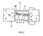
- a gas injector is attached to the end of the insertion nozzle 6 facing away from the mouth 15 and has a cylindrical housing 17.
- This housing there is a sleeve 19 which forms the conical section of the transport channel 4.
- the bushing 19 forms an annular gap section 20a with the housing 17 and a conically tapering annular gap section 20b with the body 8 of the insertion mouthpiece 6, which is in flow connection with the section 20a and is sealed off from the outside by a seal 21.
- the annular gap section 20a starts from an annular space 21 in the housing 17, which is connected via a connection bore 22 to a compressed air source (not shown).
- the annular gap section 20b opens into the mouthpiece channel 7 at 23.
- the gas injector 16 is assigned a swirl device 24 which, in the illustrated embodiment, consists of swirl grooves 24 ⁇ in the annular gap section 20b, as can be seen from the partially cut-away representation of FIG. 2. These swirl grooves can be formed in part 19 or in part 8.
- FIGS. 1-3 works as follows:
- a sliver is transported in the direction T by conventional means, for example by means of conveying air.
- the sliver is detected by a gas stream emerging from the annular gap section 20b at high speed and with twist, twisted and driven through the mouthpiece channel 7 and the mouth 15 into the conveyor nip 1 between the press rolls 2, 3.
- This way of working is particularly important at the beginning of a sliver. This beginning is “sharpened” by the twisting, so that the pointed starting piece is conveyed into the conveying gap between the rollers automatically and without interference in the further course.
- the gas flowing in the mouthpiece channel 7 can escape laterally through the longitudinal gap sections 12a, b, the radially exposed section 12c ensuring unobstructed outflow.
- the sliver is first compressed radially in the conical section of the transport channel and then by the step-like tapering of the mouthpiece channel. From the point 13 onwards, however, it can extend perpendicular to the plane E-e of the conveyor gap into the longitudinal gap sections 12a, b, so that thickenings do not lead to the formation of a jam and to tearing of the fiber sliver.
- the sliver is compressed by the walls of the longitudinal gap 12 in the plane of the conveyor gap 1, but can still extend perpendicularly to the gap.
- the sliver is then grasped by the press rolls clinging to the insertion mouthpiece 6 on both sides of the conveying nip plane and now also in Compressed direction perpendicular to the plane of the conveyor gap.
- the fiber sliver is first compressed radially from all sides, then only essentially in the plane of the conveyor gap and finally perpendicular to this plane. Since there is nowhere to fear jamming or tearing off, the sliver is reliably and trouble-free fed under compression to the pair of rollers 2, 3.
- the device according to FIG. 4 is mounted on a stationary support wall 25.
- the gas injector 16 is attached with a flange part 16a on the end face to the body 8 of the insertion mouthpiece.
- the gas injector is provided with a sleeve 19 'formed in one piece with it, which leaves an annular space 21' between it and the mouthpiece body 8 for the pressurized gas, which in this case is provided by the support wall 25 and the body 8 is supplied by setting line 26 and a radial line section 27.
- the annular gap section 20 ⁇ b starts directly from the annular space 21 ⁇ .
- the device according to FIG. 3 functions exactly like that according to FIGS. 1-3.
- the conveying gap 1 ⁇ is between a press roll 2 ⁇ rotating in the direction of the arrow and a stationary one Counter body 8 ⁇ a formed, which is integrally formed with the body 8 ⁇ of the insertion mouthpiece 6 ⁇ .
- the body 8 ⁇ in turn contains the mouthpiece channel 7 ⁇ .
- a longitudinal gap 12 ⁇ a is provided only on that side of the plane E - E of the conveyor gap 1 ⁇ on which the press roll 2 ⁇ is also located.
- a conical recess 28 is incorporated, into which a gas injector is inserted analogously to the embodiments according to FIGS. 1-3 and 4.
- the press roll 2 ⁇ is omitted. It can be seen that the counter body 8 ⁇ a forms a trough 29 which is adapted in the contour of the circular contour of the press roll 2 ⁇ .
- a further injector for introducing the transport gas for the conveyor belt can be assigned upstream of the device described.
- a e.g. capacitive, monitoring element can be arranged in the transport path of the band material, preferably (viewed in the transport direction) after the transition between the closed mouthpiece channel and the region of this channel cut by the longitudinal gap.
- the boundary surface of the outflow path formed by the longitudinal gap can merge into the outer surface of the mouthpiece without edges, as a result of which better gas separation is achieved.
- the gas injector 16 takes action for as short a time as possible and thus generates an instantaneous overpressure by means of which the beginning of the textile tape material in the delivery gap is shot.
- ends of any shape - blunt, torn off, open - can be introduced into a conveying gap.
- the walls of the insertion mouthpiece can be designed to be movable at their outlet-side area, so that after the beginning of the textile band material has been introduced into the conveyor gap, the distance between the walls can be reduced.
- FIGS 3 shows an application example of the invention, which is explained in more detail below.
- the turntable 30 of a spin can 31 shown in the illustration.
- the turntable 30 comprises an outlet elbow 33 rotatably arranged on the top of the cover 32, on the lower end of which, facing the spin can 31, a device according to the invention is arranged, as is shown in FIGS 3 has been described.
- the gas injector 16 is connected to the lower end of the outlet elbow 33.
- the mouthpiece 6 with the longitudinal slot 12 is arranged below the gas injector 16. Below the mouthpiece 6 are the two press rolls 2 and 3, which form the conveyor gap.
- the compressed air is supplied to the gas injector 16 from a compressed air source 36 via a compressed air line 34 which is passed through the swivel joint 35. While the part of the line 34 arranged between the compressed air source 36 and the swivel joint 35 is arranged stationary with respect to the cover 32, the part of the line 34 located between the swivel joint 35 and the gas injector 16 also rotates with the outlet elbow.
- the outlet manifold 33 is shown in a solid line.
- the outlet elbow In the middle of FIG. 8, in which the outlet elbow is shown in broken lines, it has already rotated 90 ° about the swivel joint 35 in relation to the position in the left half of the figure. During this rotation, the sliver is simultaneously conveyed through the outlet elbow 33 and via the gas injector 16 through the press rollers 2 and 3 and is thus deposited in the spinning can 31.
Landscapes
- Engineering & Computer Science (AREA)
- Textile Engineering (AREA)
- Mechanical Engineering (AREA)
- Treatment Of Fiber Materials (AREA)
- Spinning Or Twisting Of Yarns (AREA)
- Yarns And Mechanical Finishing Of Yarns Or Ropes (AREA)
- Advancing Webs (AREA)
- Preliminary Treatment Of Fibers (AREA)
Applications Claiming Priority (2)
| Application Number | Priority Date | Filing Date | Title |
|---|---|---|---|
| CH3783/86A CH671213A5 (fr) | 1986-09-22 | 1986-09-22 | |
| CH3783/86 | 1986-09-22 |
Publications (3)
| Publication Number | Publication Date |
|---|---|
| EP0261330A1 true EP0261330A1 (fr) | 1988-03-30 |
| EP0261330B1 EP0261330B1 (fr) | 1990-06-13 |
| EP0261330B2 EP0261330B2 (fr) | 1993-02-17 |
Family
ID=4263384
Family Applications (1)
| Application Number | Title | Priority Date | Filing Date |
|---|---|---|---|
| EP87109940A Expired - Lifetime EP0261330B2 (fr) | 1986-09-22 | 1987-07-09 | Appareil pour comprimer et pour l'enfilage automatique d'une mèche de fibres textiles dans une fente de transport |
Country Status (6)
| Country | Link |
|---|---|
| US (1) | US4809405A (fr) |
| EP (1) | EP0261330B2 (fr) |
| JP (1) | JPH0637264B2 (fr) |
| CH (1) | CH671213A5 (fr) |
| DE (1) | DE3763185D1 (fr) |
| ES (1) | ES2016307T5 (fr) |
Cited By (5)
| Publication number | Priority date | Publication date | Assignee | Title |
|---|---|---|---|---|
| EP0298519A1 (fr) * | 1987-07-09 | 1989-01-11 | Hollingsworth Gmbh | Procédé et dispositif d'emmagasinage d'un ruban de fibres textiles dans un pot |
| EP0298507A3 (fr) * | 1987-07-09 | 1991-04-17 | Hollingsworth Gmbh | Appareil pour le guidage automatique du voile de fibres en ruban |
| EP0420348A3 (en) * | 1989-09-29 | 1991-08-28 | Savio S.P.A. | Device for obtaining the roving in a finisher |
| EP0534311A1 (fr) * | 1991-09-23 | 1993-03-31 | Rosink GmbH + Co. KG | Dispositif pour déposer un ruban de fibres textiles dans un pot |
| EP3153607A1 (fr) * | 2015-10-08 | 2017-04-12 | Trützschler GmbH & Co. KG | Carde comprenant un dispositif de rattache |
Families Citing this family (6)
| Publication number | Priority date | Publication date | Assignee | Title |
|---|---|---|---|---|
| US5111551A (en) * | 1987-10-09 | 1992-05-12 | John D. Hollingsworth On Wheels, Inc. | Compact carding apparatus with sliver thread-up and method |
| DE8903356U1 (de) * | 1989-03-17 | 1990-07-19 | Hollingsworth GmbH, i.K., 75387 Neubulach | Vorrichtung zum Ablegen eines textilen Faserbandes |
| DE19537983A1 (de) * | 1995-10-12 | 1997-04-17 | Truetzschler Gmbh & Co Kg | Vorrichtung an einer Spinnereivorbereitungsmaschine, insbesondere einer Strecke, zum Messen der Stärke eines Faserbandes |
| US7103440B2 (en) * | 2001-12-11 | 2006-09-05 | Rieter Ingolstadt Spinnereimaschinenbau Ag | Use of microwaves for sensors in the spinning industry |
| DE10214955B9 (de) * | 2002-04-04 | 2017-06-29 | Rieter Ingolstadt Gmbh | Spinnereivorbereitungsmaschine |
| CN110172762A (zh) * | 2019-05-29 | 2019-08-27 | 合肥经新纺织科技有限公司 | 一种集聚分束纺纱装置和纺纱方法 |
Citations (6)
| Publication number | Priority date | Publication date | Assignee | Title |
|---|---|---|---|---|
| FR2270348A1 (fr) * | 1974-05-09 | 1975-12-05 | Luwa Ag | |
| GB2005216A (en) * | 1978-09-18 | 1979-04-19 | Nf Udviklingscenter As | Propelling head for the pneumatic propelling a multifilament tow |
| GB2059474A (en) * | 1979-09-28 | 1981-04-23 | Alsacienne Constr Meca | Fibre sheet feeding apparatus |
| US4318206A (en) | 1979-10-01 | 1982-03-09 | Luwa Ag | Coiler arrangement |
| GB2132240A (en) * | 1982-12-22 | 1984-07-04 | Textima Veb K | A funnel for spinning preparation machines |
| DE3436526A1 (de) * | 1984-10-05 | 1986-04-10 | Zinser Textilmaschinen Gmbh, 7333 Ebersbach | Bandtrichter fuer die ablieferung einer spinnereivorbereitungsmaschine |
Family Cites Families (2)
| Publication number | Priority date | Publication date | Assignee | Title |
|---|---|---|---|---|
| JPS5831123A (ja) * | 1981-08-15 | 1983-02-23 | Toyoda Autom Loom Works Ltd | 繊維束のドラフト方法および装置 |
| DE3271172D1 (en) * | 1981-10-29 | 1986-06-19 | Rieter Ag Maschf | Apparatus for a continuous compression or detection of the mass of a textile fibre sliver |
-
1986
- 1986-09-22 CH CH3783/86A patent/CH671213A5/de not_active IP Right Cessation
-
1987
- 1987-07-09 DE DE8787109940T patent/DE3763185D1/de not_active Expired - Fee Related
- 1987-07-09 EP EP87109940A patent/EP0261330B2/fr not_active Expired - Lifetime
- 1987-07-09 ES ES87109940T patent/ES2016307T5/es not_active Expired - Lifetime
- 1987-09-14 US US07/096,709 patent/US4809405A/en not_active Expired - Fee Related
- 1987-09-22 JP JP62238592A patent/JPH0637264B2/ja not_active Expired - Lifetime
Patent Citations (6)
| Publication number | Priority date | Publication date | Assignee | Title |
|---|---|---|---|---|
| FR2270348A1 (fr) * | 1974-05-09 | 1975-12-05 | Luwa Ag | |
| GB2005216A (en) * | 1978-09-18 | 1979-04-19 | Nf Udviklingscenter As | Propelling head for the pneumatic propelling a multifilament tow |
| GB2059474A (en) * | 1979-09-28 | 1981-04-23 | Alsacienne Constr Meca | Fibre sheet feeding apparatus |
| US4318206A (en) | 1979-10-01 | 1982-03-09 | Luwa Ag | Coiler arrangement |
| GB2132240A (en) * | 1982-12-22 | 1984-07-04 | Textima Veb K | A funnel for spinning preparation machines |
| DE3436526A1 (de) * | 1984-10-05 | 1986-04-10 | Zinser Textilmaschinen Gmbh, 7333 Ebersbach | Bandtrichter fuer die ablieferung einer spinnereivorbereitungsmaschine |
Cited By (9)
| Publication number | Priority date | Publication date | Assignee | Title |
|---|---|---|---|---|
| EP0298519A1 (fr) * | 1987-07-09 | 1989-01-11 | Hollingsworth Gmbh | Procédé et dispositif d'emmagasinage d'un ruban de fibres textiles dans un pot |
| WO1989000542A1 (fr) * | 1987-07-09 | 1989-01-26 | Hollingsworth Gmbh | Procede et dispositif d'entreposage de rubans de carde dans un pot de rubans |
| EP0298507A3 (fr) * | 1987-07-09 | 1991-04-17 | Hollingsworth Gmbh | Appareil pour le guidage automatique du voile de fibres en ruban |
| EP0420348A3 (en) * | 1989-09-29 | 1991-08-28 | Savio S.P.A. | Device for obtaining the roving in a finisher |
| EP0534311A1 (fr) * | 1991-09-23 | 1993-03-31 | Rosink GmbH + Co. KG | Dispositif pour déposer un ruban de fibres textiles dans un pot |
| US5269115A (en) * | 1991-09-23 | 1993-12-14 | Rosink Gmbh + Co. Kg | Device for placing a fiber ribbon into a can |
| EP3153607A1 (fr) * | 2015-10-08 | 2017-04-12 | Trützschler GmbH & Co. KG | Carde comprenant un dispositif de rattache |
| CN106987933A (zh) * | 2015-10-08 | 2017-07-28 | 特吕茨施勒有限及两合公司 | 带有接头装置的梳理机 |
| CN106987933B (zh) * | 2015-10-08 | 2019-11-08 | 特吕茨施勒有限及两合公司 | 带有接头装置的梳理机 |
Also Published As
| Publication number | Publication date |
|---|---|
| ES2016307T5 (es) | 1995-08-01 |
| ES2016307B3 (es) | 1990-11-01 |
| US4809405A (en) | 1989-03-07 |
| JPH0192179A (ja) | 1989-04-11 |
| EP0261330B1 (fr) | 1990-06-13 |
| JPH0637264B2 (ja) | 1994-05-18 |
| EP0261330B2 (fr) | 1993-02-17 |
| CH671213A5 (fr) | 1989-08-15 |
| DE3763185D1 (de) | 1990-07-19 |
Similar Documents
| Publication | Publication Date | Title |
|---|---|---|
| EP0407732B1 (fr) | Métier à filer à bout libre | |
| EP0261330B2 (fr) | Appareil pour comprimer et pour l'enfilage automatique d'une mèche de fibres textiles dans une fente de transport | |
| DE2016469C3 (de) | Offen-End-Spinnvorrichtung | |
| DE3308249A1 (de) | Oe-friktionsspinnvorrichtung | |
| CH684197A5 (de) | Spinnvorrichtung. | |
| EP1685283B1 (fr) | Canal de guidage de fibres | |
| CH674855A5 (fr) | ||
| DE19857160B4 (de) | Vorrichtung zum Offenend-Spinnen | |
| DE2718146A1 (de) | Offen-end-spinnvorrichtung | |
| EP0527355A1 (fr) | Procédé et dispositif pour l'introduction pneumatique d'une mèche de fibres dans un métier à filer | |
| DE3704460A1 (de) | Vorrichtung zum oe-rotorspinnen | |
| DE1760598B2 (de) | Offenend-Spinnvorrichrung | |
| DE3300636A1 (de) | Oe-friktionsspinnvorrichtung | |
| DE3403964A1 (de) | Vorrichtung zum oe-friktionsspinnen | |
| EP0049857B1 (fr) | Métier à tricoter circulaire pour fabriquer un tricot pelucheux ayant des fibres insérées | |
| EP0227688B1 (fr) | Dispositif de filature a fibres liberees | |
| DD233870A1 (de) | Verfahren und vorrichtung zum entfernen von fluessigkeiten aus laufenden endlosen faeden | |
| DE4227884C2 (de) | Verfahren und Vorrichtung zum pneumatischen Zuführen von Fasern zu der Fasersammelfläche eines Offenend-Spinnelementes | |
| DE3521756C2 (fr) | ||
| DE3634792C2 (de) | Friktionsspinnvorrichtung | |
| DE3821771A1 (de) | Verfahren zum abscheiden von abfall an einer baumwoll-karde und baumwoll-karde | |
| DE3135270A1 (de) | Umwindegarnspinnaggregat | |
| DE3626723C2 (fr) | ||
| DE2328611C2 (de) | Faseraufl¦sevorrichtung für eine OE-Rotorspinneinheit | |
| DE3444427C2 (de) | Vorrichtung zum Einführen eines Fadenendes in den Spinnzwickel einer Friktionsspinnvorrichtung |
Legal Events
| Date | Code | Title | Description |
|---|---|---|---|
| PUAI | Public reference made under article 153(3) epc to a published international application that has entered the european phase |
Free format text: ORIGINAL CODE: 0009012 |
|
| AK | Designated contracting states |
Kind code of ref document: A1 Designated state(s): BE CH DE ES FR GB IT LI |
|
| 17P | Request for examination filed |
Effective date: 19880309 |
|
| 17Q | First examination report despatched |
Effective date: 19890721 |
|
| GRAA | (expected) grant |
Free format text: ORIGINAL CODE: 0009210 |
|
| AK | Designated contracting states |
Kind code of ref document: B1 Designated state(s): BE CH DE ES FR GB IT LI |
|
| ITF | It: translation for a ep patent filed | ||
| GBT | Gb: translation of ep patent filed (gb section 77(6)(a)/1977) | ||
| REF | Corresponds to: |
Ref document number: 3763185 Country of ref document: DE Date of ref document: 19900719 |
|
| ET | Fr: translation filed | ||
| PLBI | Opposition filed |
Free format text: ORIGINAL CODE: 0009260 |
|
| 26 | Opposition filed |
Opponent name: ZINSER TEXTILMASCHINEN GMBH Effective date: 19910307 |
|
| ITTA | It: last paid annual fee | ||
| PUAH | Patent maintained in amended form |
Free format text: ORIGINAL CODE: 0009272 |
|
| STAA | Information on the status of an ep patent application or granted ep patent |
Free format text: STATUS: PATENT MAINTAINED AS AMENDED |
|
| 27A | Patent maintained in amended form |
Effective date: 19930217 |
|
| AK | Designated contracting states |
Kind code of ref document: B2 Designated state(s): BE CH DE ES FR GB IT LI |
|
| ITF | It: translation for a ep patent filed | ||
| GBTA | Gb: translation of amended ep patent filed (gb section 77(6)(b)/1977) |
Effective date: 19930210 |
|
| REG | Reference to a national code |
Ref country code: CH Ref legal event code: AEN |
|
| ET3 | Fr: translation filed ** decision concerning opposition | ||
| PGFP | Annual fee paid to national office [announced via postgrant information from national office to epo] |
Ref country code: ES Payment date: 19940715 Year of fee payment: 8 |
|
| PG25 | Lapsed in a contracting state [announced via postgrant information from national office to epo] |
Ref country code: ES Free format text: LAPSE BECAUSE OF THE APPLICANT RENOUNCES Effective date: 19950710 |
|
| REG | Reference to a national code |
Ref country code: ES Ref legal event code: DC2A Kind code of ref document: T5 Effective date: 19950801 |
|
| PGFP | Annual fee paid to national office [announced via postgrant information from national office to epo] |
Ref country code: FR Payment date: 19960715 Year of fee payment: 10 |
|
| PGFP | Annual fee paid to national office [announced via postgrant information from national office to epo] |
Ref country code: BE Payment date: 19960718 Year of fee payment: 10 |
|
| PG25 | Lapsed in a contracting state [announced via postgrant information from national office to epo] |
Ref country code: BE Free format text: LAPSE BECAUSE OF NON-PAYMENT OF DUE FEES Effective date: 19970731 |
|
| BERE | Be: lapsed |
Owner name: HOLLINGSWORTH G.M.B.H. Effective date: 19970731 |
|
| PG25 | Lapsed in a contracting state [announced via postgrant information from national office to epo] |
Ref country code: FR Free format text: LAPSE BECAUSE OF NON-PAYMENT OF DUE FEES Effective date: 19980331 |
|
| REG | Reference to a national code |
Ref country code: FR Ref legal event code: ST |
|
| PGFP | Annual fee paid to national office [announced via postgrant information from national office to epo] |
Ref country code: GB Payment date: 19980703 Year of fee payment: 12 |
|
| PGFP | Annual fee paid to national office [announced via postgrant information from national office to epo] |
Ref country code: CH Payment date: 19980818 Year of fee payment: 12 |
|
| PGFP | Annual fee paid to national office [announced via postgrant information from national office to epo] |
Ref country code: DE Payment date: 19980827 Year of fee payment: 12 |
|
| PG25 | Lapsed in a contracting state [announced via postgrant information from national office to epo] |
Ref country code: GB Free format text: LAPSE BECAUSE OF NON-PAYMENT OF DUE FEES Effective date: 19990709 |
|
| PG25 | Lapsed in a contracting state [announced via postgrant information from national office to epo] |
Ref country code: LI Free format text: LAPSE BECAUSE OF NON-PAYMENT OF DUE FEES Effective date: 19990731 Ref country code: CH Free format text: LAPSE BECAUSE OF NON-PAYMENT OF DUE FEES Effective date: 19990731 |
|
| REG | Reference to a national code |
Ref country code: ES Ref legal event code: FD2A Effective date: 19991007 |
|
| GBPC | Gb: european patent ceased through non-payment of renewal fee |
Effective date: 19990709 |
|
| REG | Reference to a national code |
Ref country code: CH Ref legal event code: PL |
|
| PG25 | Lapsed in a contracting state [announced via postgrant information from national office to epo] |
Ref country code: DE Free format text: LAPSE BECAUSE OF NON-PAYMENT OF DUE FEES Effective date: 20000503 |
|
| PG25 | Lapsed in a contracting state [announced via postgrant information from national office to epo] |
Ref country code: IT Free format text: LAPSE BECAUSE OF NON-PAYMENT OF DUE FEES;WARNING: LAPSES OF ITALIAN PATENTS WITH EFFECTIVE DATE BEFORE 2007 MAY HAVE OCCURRED AT ANY TIME BEFORE 2007. THE CORRECT EFFECTIVE DATE MAY BE DIFFERENT FROM THE ONE RECORDED. Effective date: 20050709 |