EP0261343A2 - Procédé pour réaliser des saillies de profilage sur des pièces en acier, revêtues de matière synthétique et pièces en acier revêtues ainsi obtenues - Google Patents
Procédé pour réaliser des saillies de profilage sur des pièces en acier, revêtues de matière synthétique et pièces en acier revêtues ainsi obtenues Download PDFInfo
- Publication number
- EP0261343A2 EP0261343A2 EP87110813A EP87110813A EP0261343A2 EP 0261343 A2 EP0261343 A2 EP 0261343A2 EP 87110813 A EP87110813 A EP 87110813A EP 87110813 A EP87110813 A EP 87110813A EP 0261343 A2 EP0261343 A2 EP 0261343A2
- Authority
- EP
- European Patent Office
- Prior art keywords
- powder
- plastic coating
- coating
- steel
- profiling
- Prior art date
- Legal status (The legal status is an assumption and is not a legal conclusion. Google has not performed a legal analysis and makes no representation as to the accuracy of the status listed.)
- Withdrawn
Links
Images


Classifications
-
- E—FIXED CONSTRUCTIONS
- E04—BUILDING
- E04C—STRUCTURAL ELEMENTS; BUILDING MATERIALS
- E04C5/00—Reinforcing elements, e.g. for concrete; Auxiliary elements therefor
- E04C5/07—Reinforcing elements of material other than metal, e.g. of glass, of plastics, or not exclusively made of metal
-
- B—PERFORMING OPERATIONS; TRANSPORTING
- B05—SPRAYING OR ATOMISING IN GENERAL; APPLYING FLUENT MATERIALS TO SURFACES, IN GENERAL
- B05D—PROCESSES FOR APPLYING FLUENT MATERIALS TO SURFACES, IN GENERAL
- B05D5/00—Processes for applying liquids or other fluent materials to surfaces to obtain special surface effects, finishes or structures
- B05D5/02—Processes for applying liquids or other fluent materials to surfaces to obtain special surface effects, finishes or structures to obtain a matt or rough surface
-
- B—PERFORMING OPERATIONS; TRANSPORTING
- B05—SPRAYING OR ATOMISING IN GENERAL; APPLYING FLUENT MATERIALS TO SURFACES, IN GENERAL
- B05D—PROCESSES FOR APPLYING FLUENT MATERIALS TO SURFACES, IN GENERAL
- B05D7/00—Processes, other than flocking, specially adapted for applying liquids or other fluent materials to particular surfaces or for applying particular liquids or other fluent materials
- B05D7/14—Processes, other than flocking, specially adapted for applying liquids or other fluent materials to particular surfaces or for applying particular liquids or other fluent materials to metal, e.g. car bodies
-
- B—PERFORMING OPERATIONS; TRANSPORTING
- B28—WORKING CEMENT, CLAY, OR STONE
- B28B—SHAPING CLAY OR OTHER CERAMIC COMPOSITIONS; SHAPING SLAG; SHAPING MIXTURES CONTAINING CEMENTITIOUS MATERIAL, e.g. PLASTER
- B28B19/00—Machines or methods for applying the material to surfaces to form a permanent layer thereon
- B28B19/0038—Machines or methods for applying the material to surfaces to form a permanent layer thereon lining the outer wall of hollow objects, e.g. pipes
-
- B—PERFORMING OPERATIONS; TRANSPORTING
- B29—WORKING OF PLASTICS; WORKING OF SUBSTANCES IN A PLASTIC STATE IN GENERAL
- B29D—PRODUCING PARTICULAR ARTICLES FROM PLASTICS OR FROM SUBSTANCES IN A PLASTIC STATE
- B29D23/00—Producing tubular articles
- B29D23/001—Pipes; Pipe joints
-
- E—FIXED CONSTRUCTIONS
- E04—BUILDING
- E04C—STRUCTURAL ELEMENTS; BUILDING MATERIALS
- E04C5/00—Reinforcing elements, e.g. for concrete; Auxiliary elements therefor
- E04C5/01—Reinforcing elements of metal, e.g. with non-structural coatings
-
- E—FIXED CONSTRUCTIONS
- E04—BUILDING
- E04C—STRUCTURAL ELEMENTS; BUILDING MATERIALS
- E04C5/00—Reinforcing elements, e.g. for concrete; Auxiliary elements therefor
- E04C5/01—Reinforcing elements of metal, e.g. with non-structural coatings
- E04C5/02—Reinforcing elements of metal, e.g. with non-structural coatings of low bending resistance, i.e. of essentially one-dimensional [1D] or two-dimensional [2D] extent
- E04C5/03—Reinforcing elements of metal, e.g. with non-structural coatings of low bending resistance, i.e. of essentially one-dimensional [1D] or two-dimensional [2D] extent with indentations, projections, ribs, or the like, for augmenting the adherence to the concrete
-
- F—MECHANICAL ENGINEERING; LIGHTING; HEATING; WEAPONS; BLASTING
- F16—ENGINEERING ELEMENTS AND UNITS; GENERAL MEASURES FOR PRODUCING AND MAINTAINING EFFECTIVE FUNCTIONING OF MACHINES OR INSTALLATIONS; THERMAL INSULATION IN GENERAL
- F16L—PIPES; JOINTS OR FITTINGS FOR PIPES; SUPPORTS FOR PIPES, CABLES OR PROTECTIVE TUBING; MEANS FOR THERMAL INSULATION IN GENERAL
- F16L9/00—Rigid pipes
- F16L9/14—Compound tubes, i.e. made of materials not wholly covered by any one of the preceding groups
-
- B—PERFORMING OPERATIONS; TRANSPORTING
- B29—WORKING OF PLASTICS; WORKING OF SUBSTANCES IN A PLASTIC STATE IN GENERAL
- B29K—INDEXING SCHEME ASSOCIATED WITH SUBCLASSES B29B, B29C OR B29D, RELATING TO MOULDING MATERIALS OR TO MATERIALS FOR MOULDS, REINFORCEMENTS, FILLERS OR PREFORMED PARTS, e.g. INSERTS
- B29K2705/00—Use of metals, their alloys or their compounds, for preformed parts, e.g. for inserts
- B29K2705/08—Transition metals
- B29K2705/12—Iron
-
- B—PERFORMING OPERATIONS; TRANSPORTING
- B29—WORKING OF PLASTICS; WORKING OF SUBSTANCES IN A PLASTIC STATE IN GENERAL
- B29L—INDEXING SCHEME ASSOCIATED WITH SUBCLASS B29C, RELATING TO PARTICULAR ARTICLES
- B29L2009/00—Layered products
- B29L2009/003—Layered products comprising a metal layer
-
- B—PERFORMING OPERATIONS; TRANSPORTING
- B29—WORKING OF PLASTICS; WORKING OF SUBSTANCES IN A PLASTIC STATE IN GENERAL
- B29L—INDEXING SCHEME ASSOCIATED WITH SUBCLASS B29C, RELATING TO PARTICULAR ARTICLES
- B29L2023/00—Tubular articles
- B29L2023/22—Tubes or pipes, i.e. rigid
Definitions
- the invention relates to a method for sheathing steel parts, on the outer surface of which a plastic coating is applied, which can be brought into contact or is in contact with a sheathing material at least in certain areas, the interface with the sheathing material formed by the outer surface of the plastic coating being provided with profiling projections.
- Such a method emerges from DE-OS 35 31 618.
- a steel pipe is provided with a thermoplastic layer, to which an external coating based on concrete is subsequently applied.
- the plastic coating is carried out by helically overlapping wrapping with an extruded film strip, which is provided with at least one thickening extending in the form of strips over the entire length of the film strip.
- the thickening is arranged on the edge of the film strip which is not overlapped by a subsequent layer of the film strip.
- the concrete coating is used in particular to weigh down the pipes in order to ensure the hydrostatic buoyancy of the empty pipes when laying offshore pipelines Balance pipes by additional weight.
- considerable tensile loads occur which are transmitted from the holding devices of the laying ships to the steel pipes via the casing.
- the strip-shaped, thickened areas of the film tape embedded in the concrete coating serve to increase the adhesion between the plastic casing and the concrete casing.
- the invention has for its object to provide a method of the type mentioned and a corresponding steel part, which leads to increased adhesion between the plastic coating and encapsulation material in a particularly simple manner.
- no special extruder nozzles should be necessary in the case of a thermoplastic plastic coating.
- This object is achieved in that a granular powder or granulate is applied to the not yet fully cured plastic coating in such a way that the individual powder grains for forming the profiling projections are only partially absorbed by the coating surface. Due to the incomplete solidification of the plastic coating, the powder can only partially penetrate into the plastic coating surface; ie the individual granules of the powder project over the plastic coating surface due to their partial embedding with a surface area. In this way, a rough covering is created which, on the one hand, considerably increases the coating surface and, on the other hand, creates projections which are encased by the embedding compound, preferably concrete or encapsulation material based on concrete, when the steel part is embedded.
- the embedding compound preferably concrete or encapsulation material based on concrete
- the bond between this coated steel part and the embedding compound is thus increased Lich increased.
- the invention is therefore advantageous for reinforcing steel as well as for the formation of a steel construction joint.
- the steel construction impact which is not embedded in an embedding compound, two steel components are fastened together under tension.
- the shear stresses that occur are transmitted to one another by surface friction between the two components.
- the surface friction is considerably increased by the rough covering according to the invention, which is advantageous for the power transmission.
- the plastic coating also protects the steel component from corrosion damage.
- the plastic coating can consist of a thermoplastic or an epoxy resin.
- the steel component to be coated is heated and applied to the heated surface of the plastic, for example in the form of an extruded film strip or film tube.
- a thermoplastic for example polyethylene
- the steel component to be coated is heated and applied to the heated surface of the plastic, for example in the form of an extruded film strip or film tube.
- plastic powder is applied as the powder.
- a rough covering is also formed when using ceramic powder or stone powder (eg sand).
- metallic powder is also possible, but it must be ensured that this does not penetrate to the steel surface, since otherwise the corrosion protection is in question.
- the process sequence can be such that a thermoplastic layer, in particular a polyethylene layer, is applied as the plastic coating and is in a gelling state when the powder is applied by heat treatment.
- a thermoplastic layer in particular a polyethylene layer
- the residual heat that the steel part still has immediately after the plastic coating can be used.
- the powder is applied to the gelling coating film of the plastic coating, it partially penetrates into the surface of the coating film and sticks to it.
- a thermoplastic powder in particular a polyethylene powder, is applied as the powder, this is melted by the residual heat, but it is not entirely absorbed by the gelling coating film. The melting creates an intimate connection to the other plastic coating.
- Polyethylene and / or ethylene copolymer is preferably used for the plastic coating and / or the powder.
- thermoset layer in particular an epoxy resin layer
- the plastic coating which layer is still in a sticky state when the powder is applied due to incomplete curing.
- the powder is thus applied before the plastic coating surface solidifies, so that the Connect individual grains of the powder homogeneously with the plastic layer in the course of a chemical reaction process and be fixed in this way.
- a thermoset powder, in particular epoxy resin powder is preferably applied as powder.
- the powder is blown onto the plastic coating.
- the application of the powder can preferably be supported by an electrostatic field.
- the powder can also be sprinkled on or applied in fluidized form.
- the powder can also be relatively coarse-grained, so that it is a granulate that preferably consists of the materials mentioned.
- the invention relates to a method for sheathing steel parts, in particular pipes, to the outer surface of which a plastic coating is applied, which can be brought into contact or at least with a sheathing material, the interface formed by the outer surface of the sheathing material with profiling projections is provided and wherein the profiling projections are formed by the side flanks of a helical rib extruded onto the heated plastic coating.
- the steel component is an elongated object, for example a tube
- the profiling projections form steps lying transversely to the longitudinal direction of the object.
- the longitudinal displacement forces occurring between the sheathing material and the pipe are absorbed by the positive connection formed by the profiling projections.
- Due to the helical rib steps lying transversely to the longitudinal direction of the tube are formed. The size of the steps depends on the diameter of the pipe or the weight of the concrete casing and the steel pipe itself. According to the invention, it is provided that the plastic coating is first applied to the steel part and then the helical rib is extruded onto this coating.
- the plastic coating is preferably a thermoplastic layer, so that the successive application of coating and spiral rib leads to the advantage that no special extruder nozzles, as are known from the prior art (DE-OS 35 31 618), have to be used, which create the coating and the rib at the same time. Rather, the coating is carried out according to the invention independently of the rib formation, so that, depending on the application, the correct shape or size of the extruder nozzle for the rib can be selected independently of the extruder nozzle for the plastic coating.
- the coating system can therefore be adapted very quickly to the desired application by simply replacing the extruder extruder nozzle.
- the helical rib is applied to the outside of the web and / or the fastening side of the helical rib with a heat source to maintain the surface melting temperature immediately after the thermoplastic plastic coating has been applied to it.
- the steel structure that is still hot after the plastic coating has been applied Part is then immediately provided with the rib, which makes sense in terms of energy.
- the plastic coating or the fastening side of the rib must be kept at the surface melting temperature. It is sufficient if only a few ⁇ m of the corresponding surface is kept in the molten state. There is an intimate fusion at the point of contact.
- the applied plastic coating is cooled until the spiral fin is applied to increase the structural strength of the plastic coating.
- This has the advantage that the cooled plastic coating is able to absorb forces, so that the shrinkage stresses subsequently exerted by the spiral rib and caused by its cooling can be absorbed without damage.
- the remelting of the surface of the plastic coating that occurs during the application of the ribs does not interfere, because the melting takes place only in a depth range of a few ⁇ m, which does not detract from the structural strength achieved by the cooling in the remaining area.
- the invention relates to a steel component provided with a plastic coating, which can be embedded or embedded at least in some areas in a encapsulation material and wherein the interface to the encapsulation material formed by the outer surface of the plastic coating is provided with profiling projections.
- the profiling projections (rough covering) of the plastic coating are formed by powder grains or granules protruding from the surface of the coating.
- the powder is preferably a plastic powder or plastic granules. The same material can be provided for plastic coating and powder.
- an advantageous feature is that a different hardness of the profiling projections and the plastic coating, in particular the extruded web, is provided.
- a particularly firm connection to the encapsulation material can be achieved in particular in that the profiling projections consist of the harder material.
- the arrangement can be such that the encapsulation material is fixed in place to fix the steel part, which is designed in particular as a tube.
- the encapsulation material can be designed as an anchor block that can be fixed in the ground. This opens up the possibility of, for example, fixing the individual pipes welded together in a fixed position at certain points in a pipeline.
- the anchor block which is preferably made of concrete, in the ground, the steel pipe is fixed at this point because, due to the profiling projections according to the invention, there is a firm bond between the steel pipe and anchor block.
- a pipe section provided with retaining anchors surrounds the steel component for fixing the steel component provided with profiling projections, the inside of the pipe section being provided with a profiling which absorbs axial forces and the annular space between the steel component and the pipe section is filled with a hardened compound .
- This also allows the steel component, for example a pipe, to be fixed in place by anchoring the retaining anchors, for example, to a concrete foundation or to a corresponding construction be attached.
- the pipe section is fixed via the holding anchors, which in turn is immovably connected to the profiling sections via the hardened composite. A shift of the composite mass is excluded, since it engages on the one hand in the profiling projections of the coating and on the other hand is held by the inside profiling of the pipe section.
- concrete can be used as the compound, but synthetic resin is preferably used.
- a spiral web attached there, e.g. a welded-on steel spiral bridge, provided that the pipe section is also made of steel.
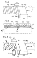
- Fig. 1 shows a steel part 1, which is designed as a rod-shaped reinforcing steel 2.
- the surface 2 has elevations 4 in order to obtain the strongest possible hold when embedding in concrete.
- a plastic coating 5 is applied to the surface 3 of the reinforcing steel 2.
- the plastic coating 5 is a polyethylene layer 6.
- a powder 8, which forms a friction lining 9, is applied to the surface 7 of the polyethylene layer 6; i.e. the individual grains of powder 8 form a rough surface structure.
- the powder 8 is preferably polyethylene powder which is melted by heat treatment, but is not entirely absorbed by the surface 7.
- FIG. 3 shows a further embodiment of the invention, which is also a cross section through a reinforcing steel 2. Compared to the previously described exemplary embodiment, however, there is the difference that an epoxy resin layer 11 is applied as the plastic coating 5, in the surface 12 of which the grains of the powder 8 are partially accommodated.
- a thermoset powder 13, preferably an epoxy powder, is preferably used as powder 8.
- the surface roughness can be varied, for example similar to an orange peel, up to the sharp-edged, large-area emergence of the grains.
- the pipe 101 which is designed as a pipeline pipe, has an inner, surface-conditioned steel pipe 102 that represents a steel part 102. With regard to the conditioning, it can be a phosphatisation, for example.
- Another component of the pipeline pipe 101 is an inner sheath 103 made of plastic and surrounding the steel pipe 102. Thermoplastics are particularly suitable for this.
- An outer casing 104 made of reinforced concrete is then also provided.
- a helical rib 105 extending from the inner casing 103 is provided according to the embodiment in FIG. 5.
- the side flanks 105 ⁇ of the spiral paths of the rib 105 designed in flat form represent profiling projections which protrude into the concrete casing 104 and lead to a positive fit.
- the helically applied rib 105 extends from the outer surface 103 ⁇ of the inner casing 103 and is firmly connected to it.
- the rib 105 it is also a thermoplastic material which is chosen to be harder than that of the inner casing 103.
- the coating of the surface-conditioned tube 102 with the inner casing 103 is shown in FIG. 6.
- a web 108 coming from an extruder nozzle 107 is wound onto the steel tube 102 provided with a thin adhesive layer 106.
- the steel tube 102 executes a superimposed movement. In addition to a rotation in the direction of the arrow x, it is moved past the extruder nozzle 107 in the direction of the arrow y. In this way, the extruded sheet 108 is wound onto the steel pipe 102 and forms the inner one Sheath 103.
- the tube is heated to the required temperature during this application.
- the extruder nozzle 107 is adjacent to an additional extruder nozzle 109.
- This forms the rib 105 which is wound onto the casing 103 in a helical manner.
- This application of the rib 105 takes place at the melting temperature in such a way that there is no melting effect. Since the application of the rib 105 is arranged downstream, an infrared radiator 110 is installed opposite the additional extruder nozzle 109 in order to achieve a sufficient melting temperature.
- the layering of the pipe provided with the inner casing 103 and the rib 105 can then be carried out in the subsequent manner in the usual manner, the concrete entering the spaces between the spiral passages.
- the latter form steps lying transversely to the longitudinal direction of the pipe, which lead to a great positional stability of the concrete jacket on the steel pipe 102 in the axial direction.
- 7 and 8 illustrate the manufacture of the embodiment of a steel component designed as a tube, the inner sheath 103 being applied in the same way as before, by winding a web 108 coming from the extruder nozzle 107 onto the steel tube 102 carrying out a superimposed movement becomes.
- the extruder nozzle 107 is followed by a feed device 111.
- This contains preheated, ground, plastic 112 powder or granules, which are applied to the plastic-coated tube in a suitable manner.
- An infrared radiator 113 which conforms to the regulations, is also arranged opposite the loading device 111 Fusion temperature generated.
- the granules 112 come into contact with the inner casing 103, without a melting effect, so that in this way the outer surface 103 ⁇ of the casing 103 protruding profiling projections are formed, see in particular Fig. 7.
- the granule profiling projections 112 also form transversely to the longitudinal direction of the Pipe extending steps 112 ⁇ , which lead to a positive connection between the concrete casing 104 and the inner casing 103.
- the size of the powder grains or granules can vary.
- the granules 112 can have a greater hardness than the inner casing 103.
- a device for cooling the plastic coating is shown schematically in FIG. 8 and identified by reference number 120.
- the cooling device 120 lies between the extruder nozzle 107 for the plastic coating and the loading device 111 for the application of the profiling projections.
- Such a cooling device can also be provided in the exemplary embodiment according to FIG. 6 (not shown); it would then lie between the extruder nozzle 107 and the additional extruder nozzle 109.
- the cooling of the plastic coating applied under the effect of heat gives it a structural strength, so that the shrinkage stresses which occur after the subsequently applied spiral fin can be absorbed during cooling without the coating being damaged.
- the steel part being a plastic-coated tube with melted-in powder or granules, as shown in FIG. 8.
- the plastic coating does not have to be produced by extruder coils, rather it is alternatively also possible to extrude a hose which is applied to the steel tube.
- the encapsulation material is not, as described above, designed as a tube surrounding the tube, preferably made of concrete, but rather forms a cuboid block 130.
- This block 130 can preferably consist of concrete and only extend over a partial length of the tube.
- the coated tube 102 has powder or granules 112 on its plastic coating, at least in the area of the block 130, so that there is an intimate connection between the block 130 and the plastic coating.
- the pipe 102 passing through the block 130 is fixed immovably relative to the block 130.
- the Block 130 can form an anchor block if, for example, it is buried in the ground or otherwise fixed.
- pipelines can be used to create fixed points that define the pipe that expands when it is hot and contracts when it is cold.
- FIG. 10 shows a further exemplary embodiment, which differs from that of FIG. 9 only in that the tube has profiled projections designed as a spiral rib 105.
- FIG. 11 A further embodiment variant for fixing the tube is shown in FIG. 11.
- the tube 102 is coaxially surrounded in some areas by a tube section 131, an annular space 132 being created between the tube 102 and the tube section 131.
- a profile 133 is formed on the inside of the pipe section 131, which can be designed as a spiral web 134 connected to the inside of the pipe section 131.
- the tube 102 is plastic-coated and has, at least in the region of the tube section 131, profiling projections which, according to FIG. 11, are designed as powder or granulate particles 112.
- Retaining anchors 135 are fastened to the outside of the tube section 131 and are embedded in a fixing material 136.
- the fixing material 136 can be, for example, a concrete component, which in turn is fixed in the ground or the like. Furthermore, it is also possible to attach the holding anchors 135 to other constructions.
- the annular space 132 is filled with a hardened compound 137. In this way, there is an intimate connection between the tube 102 and the pipe socket 131, since the Compound 137 has entered between the profiling projections 112 and the profiling 133 prior to hardening and in this respect prevents axial displacement between the pipe section 133 and the pipe 102.
- the pipe section 133 is held in the fixing material 136 by the holding anchors 135. In this way, a fixing possibility for the tube 102 is thus created - just as in FIGS. 9 and 10-.
- FIG. 12 shows a further exemplary embodiment, which differs from FIG. 11 only in that the tube is not provided with profiling projections made of powder or granulate bodies, but instead has a spiral rib 105 on its plastic coating.
- Synthetic resin can preferably be used as the composite compound 137. However, it is also possible to use concrete.
Landscapes
- Engineering & Computer Science (AREA)
- Architecture (AREA)
- Civil Engineering (AREA)
- Structural Engineering (AREA)
- Mechanical Engineering (AREA)
- General Engineering & Computer Science (AREA)
- Chemical & Material Sciences (AREA)
- Wood Science & Technology (AREA)
- Life Sciences & Earth Sciences (AREA)
- Ceramic Engineering (AREA)
- Lining Or Joining Of Plastics Or The Like (AREA)
- Application Of Or Painting With Fluid Materials (AREA)
- Laminated Bodies (AREA)
- Coating With Molten Metal (AREA)
- Protection Of Pipes Against Damage, Friction, And Corrosion (AREA)
- Bridges Or Land Bridges (AREA)
- Extrusion Moulding Of Plastics Or The Like (AREA)
Priority Applications (1)
| Application Number | Priority Date | Filing Date | Title |
|---|---|---|---|
| EP90125361A EP0423849B1 (fr) | 1986-08-23 | 1987-07-25 | Procédé pour enduire des pièces en acier avec une couche en plastique |
Applications Claiming Priority (4)
| Application Number | Priority Date | Filing Date | Title |
|---|---|---|---|
| DE3628704 | 1986-08-23 | ||
| DE19863628704 DE3628704A1 (de) | 1986-08-23 | 1986-08-23 | Rohr, insbesondere pipeline-rohr |
| DE3711420 | 1987-04-04 | ||
| DE19873711420 DE3711420A1 (de) | 1986-08-23 | 1987-04-04 | Verfahren zur schaffung eines rauhbelages auf kunststoffummantelten stahlteilen |
Related Child Applications (2)
| Application Number | Title | Priority Date | Filing Date |
|---|---|---|---|
| EP90125361.7 Division-Into | 1987-07-25 | ||
| EP90125361A Division EP0423849B1 (fr) | 1986-08-23 | 1987-07-25 | Procédé pour enduire des pièces en acier avec une couche en plastique |
Publications (2)
| Publication Number | Publication Date |
|---|---|
| EP0261343A2 true EP0261343A2 (fr) | 1988-03-30 |
| EP0261343A3 EP0261343A3 (fr) | 1989-04-26 |
Family
ID=25846831
Family Applications (1)
| Application Number | Title | Priority Date | Filing Date |
|---|---|---|---|
| EP87110813A Withdrawn EP0261343A3 (fr) | 1986-08-23 | 1987-07-25 | Procédé pour réaliser des saillies de profilage sur des pièces en acier, revêtues de matière synthétique et pièces en acier revêtues ainsi obtenues |
Country Status (5)
| Country | Link |
|---|---|
| US (1) | US4929294A (fr) |
| EP (1) | EP0261343A3 (fr) |
| CA (1) | CA1282650C (fr) |
| DK (1) | DK172586B1 (fr) |
| NO (1) | NO170997C (fr) |
Cited By (3)
| Publication number | Priority date | Publication date | Assignee | Title |
|---|---|---|---|---|
| WO1991012090A1 (fr) * | 1990-02-14 | 1991-08-22 | Eric Joseph Harvison | Surfaces anti-derapage |
| WO1994026426A1 (fr) * | 1993-05-14 | 1994-11-24 | British Pipe Coaters Limited | Revetement de conduit |
| EP0676506A3 (fr) * | 1990-02-14 | 1996-01-31 | Safeway Traffic Uk Ltd | Surfaces anti-glissement. |
Families Citing this family (19)
| Publication number | Priority date | Publication date | Assignee | Title |
|---|---|---|---|---|
| US5176940A (en) * | 1989-02-28 | 1993-01-05 | Valmet Paper Machinery Inc. | Method for forming a coated roll |
| JPH10501325A (ja) * | 1994-06-07 | 1998-02-03 | パイプフォーム エルエルシー | 連結されたプラスチックで被覆したコンクリート・パイプ |
| US5725928A (en) * | 1995-02-17 | 1998-03-10 | Velcro Industries B.V. | Touch fastener with magnetic attractant |
| US6540863B2 (en) | 1995-02-17 | 2003-04-01 | Velcro Industries B.V. | Forming fastener components of multiple streams of resin |
| GB9721974D0 (en) * | 1997-10-17 | 1997-12-17 | Rother Boiler Company Limited | Construction fitting |
| GB2332492A (en) * | 1997-12-22 | 1999-06-23 | Draftex Ind Ltd | Multi-layer fuel pipe |
| FR2785968B1 (fr) | 1998-11-16 | 2001-01-12 | Inst Francais Du Petrole | Conduite isolee thermiquement par un materiau elastomere et methode de fabrication |
| US6605316B1 (en) | 1999-07-31 | 2003-08-12 | The Regents Of The University Of California | Structures and fabrication techniques for solid state electrochemical devices |
| CN100574953C (zh) * | 2004-11-30 | 2009-12-30 | 加州大学评议会 | 热膨胀系数相匹配的钎焊体系 |
| WO2006091250A2 (fr) * | 2004-11-30 | 2006-08-31 | The Regents Of The University Of California | Jonction de materiaux dissemblables |
| JP2008522370A (ja) * | 2004-11-30 | 2008-06-26 | ザ、リージェンツ、オブ、ザ、ユニバーシティ、オブ、カリフォルニア | 電気化学装置用封止ジョイント構造 |
| US7509783B1 (en) | 2005-07-01 | 2009-03-31 | Thomas Matousek | Reinforcing rod |
| CA2656460A1 (fr) * | 2006-07-28 | 2008-02-07 | The Regents Of The University Of California | Tubes concentriques reunis |
| KR20100065296A (ko) * | 2007-07-25 | 2010-06-16 | 더 리전트 오브 더 유니버시티 오브 캘리포니아 | 맞물림 구조를 가지는 고온 전기화학 소자 |
| DK2250295T3 (da) * | 2008-02-04 | 2012-04-16 | Univ California | Cu-baseret cermet til højtemperatur-brændstofceller |
| RU2010147046A (ru) | 2008-04-18 | 2012-05-27 | Члены Правления Университета Калифорнии (Us) | Комбинированное уплотнение для высокотемпературного электрохимического устройства |
| GB0812071D0 (en) * | 2008-07-02 | 2008-08-06 | Pipeline Tech Ltd | Pipe coating |
| US9573843B2 (en) | 2013-08-05 | 2017-02-21 | Corning Incorporated | Polymer edge-covered glass articles and methods for making and using same |
| JP6759242B2 (ja) | 2015-05-01 | 2020-09-23 | ヴァルスパー・ソーシング・インコーポレーテッド | 高性能テクスチャコーティング |
Citations (3)
| Publication number | Priority date | Publication date | Assignee | Title |
|---|---|---|---|---|
| GB2137304A (en) | 1983-03-30 | 1984-10-03 | Sif Societe Ind D Isolation Et | Arrangement permitting the fixing of ballasting on synthetic protective coatings of tubes intended to be submerged, and its process of manufacture |
| DE3326711A1 (de) | 1983-07-25 | 1985-02-14 | Jürgen Detlev 8130 Starnberg Härtel | Einrichtung zur rueckspeisung von anrufsignalen eines telefons in die anruferleitung |
| EP0137663A1 (fr) | 1983-08-25 | 1985-04-17 | Shaw Industries Ltd. | Revêtement de résine imperméable à l'humidité et résistant au choc et méthode pour son application |
Family Cites Families (30)
| Publication number | Priority date | Publication date | Assignee | Title |
|---|---|---|---|---|
| US1797443A (en) * | 1928-08-24 | 1931-03-24 | Banner Rock Corp | Monolithic underground insulation |
| US3944641A (en) * | 1961-10-02 | 1976-03-16 | Lemelson Jerome H | Process of forming an irregular surface on the inside of a tube or pipe |
| FR1355761A (fr) * | 1963-02-07 | 1964-03-20 | Pneumatiques, Caoutchouc Manufacture Et Plastiques Kleber-Colombes | Procédé de collage des polymères thermoplastiques sur surfaces métalliques |
| US3599435A (en) * | 1969-08-28 | 1971-08-17 | Shell Oil Co | Method for laying coated pipelines underwater |
| DE2127732A1 (en) * | 1971-06-04 | 1972-12-14 | Lechler Chemie GmbH, 7000 Stutt gart | Roughened non-slip plastic surface - through scattering of water-soluble crystals to be washed out when plastic hardens |
| US3904346A (en) * | 1971-12-23 | 1975-09-09 | Leslie Earl Shaw | Electrostatic powder coating process |
| JPS5158595A (ja) * | 1974-11-18 | 1976-05-21 | Morishita Chem Ind | Enshinhoriorefuinhokyoito |
| GB1532544A (en) * | 1976-01-27 | 1978-11-15 | Bechtel Int Corp | Composite pipeline |
| JPS543699A (en) * | 1977-06-08 | 1979-01-11 | Toshiba Corp | Protector of ion source |
| SU654421A1 (ru) * | 1977-06-20 | 1979-03-30 | Новосибирский Институт Инженеров Железнодорожного Транспорта | Способ нанесени покрыти на арматуру железобетонных изделий |
| US4211595A (en) * | 1978-10-10 | 1980-07-08 | The Kendall Company | Method of coating pipe |
| US4213486A (en) * | 1978-11-06 | 1980-07-22 | The Kendall Company | Coated pipe and process for making same |
| JPS55124622A (en) * | 1979-03-20 | 1980-09-25 | Nippon Steel Corp | Production of plastic-covered steel pipe for concrete coating |
| JPS5678933A (en) * | 1979-11-30 | 1981-06-29 | Sumitomo Metal Ind Ltd | Preparation of plastic coated steel pipe |
| DE2952540A1 (de) * | 1979-12-28 | 1981-07-02 | Dyckerhoff & Widmann AG, 8000 München | Verfahren zum herstellen eines betonrohrs mit korrosionsbestaendiger auskleidung |
| SU874366A1 (ru) * | 1980-02-20 | 1981-10-23 | Южный Филиал Всесоюзного Дважды Ордена Трудового Красного Знамени Теплотехнического Научно-Исследовательского Института Им.Ф.Э.Дзержинского | Способ защиты бетона |
| JPS579870A (en) * | 1980-06-17 | 1982-01-19 | Ricoh Co Ltd | Formation of vapor-deposited film consisting of two or more elements |
| JPS5791231A (en) * | 1980-11-28 | 1982-06-07 | Nippon Kokan Kk <Nkk> | Roughening method for surface of steel pipe coated with plastic |
| DE3047429C2 (de) * | 1980-12-12 | 1984-09-13 | Mannesmann AG, 4000 Düsseldorf | Verfahren zum Ummanteln eines Stahlrohres |
| DE3121773C2 (de) * | 1981-05-27 | 1984-06-07 | Mannesmann AG, 4000 Düsseldorf | Extruderkopf zum Ummanteln eines Stahlrohres |
| JPS5851130A (ja) * | 1981-09-22 | 1983-03-25 | Nippon Kokan Kk <Nkk> | ポリエチレン被覆鋼管 |
| DE3247510C2 (de) * | 1982-07-06 | 1984-12-06 | Mannesmann AG, 4000 Düsseldorf | Verfahren zum Ummanteln eines Formkörpers und Anwendung des Verfahrens auf einen Formkörper mit einer wärmeempfindlichen Innenschicht |
| DE3311893A1 (de) * | 1983-03-31 | 1984-10-04 | Société SIF Sté. Industrielle d'Isolation et de Fournitures d'Usines S.A., Le Plan, Velaux | Einrichtung zum befestigen einer ballastschicht aus beton auf der schutzummantelung von unter wasser zu verlegenden rohren |
| DE3326701C2 (de) * | 1983-07-23 | 1985-05-30 | Hüni + Co KG, 7990 Friedrichshafen | Verfahren zur Aufbringung eines rauhen Oberflächenbelages auf einem Werkstück |
| DD234334A3 (de) * | 1984-03-01 | 1986-04-02 | Rohrkombinat Stahl & Walzwerk | Verfahren zur herstellung von metallrohren mit polyolefinueberzug |
| JPS60201927A (ja) * | 1984-03-26 | 1985-10-12 | Nippon Steel Corp | プラスチツク被覆鋼管の製造方法 |
| US4560607A (en) * | 1984-06-07 | 1985-12-24 | The Duriron Company, Inc. | Method of joining materials by mechanical interlock and article |
| DE3512528A1 (de) * | 1985-04-06 | 1986-10-09 | Röhrenwerk Gebr. Fuchs GmbH, 5900 Siegen | Verfahren zum aufbringen einer schutzschicht auf gegenstaende mit glatter oberflaeche |
| DE3531618A1 (de) * | 1985-09-02 | 1987-03-12 | Mannesmann Ag | Verfahren zum ummanteln eines stahlrohres |
| DE3607459A1 (de) * | 1986-03-07 | 1987-09-17 | Europ Chemical Ind | Metallrohr, insbesondere stahlrohr, mit einem korrosionsschutzueberzug und einem schutzmantel |
-
1987
- 1987-07-25 EP EP87110813A patent/EP0261343A3/fr not_active Withdrawn
- 1987-08-14 US US07/086,101 patent/US4929294A/en not_active Expired - Lifetime
- 1987-08-18 DK DK198704288A patent/DK172586B1/da not_active IP Right Cessation
- 1987-08-19 CA CA000544824A patent/CA1282650C/fr not_active Expired - Lifetime
- 1987-08-21 NO NO873548A patent/NO170997C/no not_active IP Right Cessation
Patent Citations (3)
| Publication number | Priority date | Publication date | Assignee | Title |
|---|---|---|---|---|
| GB2137304A (en) | 1983-03-30 | 1984-10-03 | Sif Societe Ind D Isolation Et | Arrangement permitting the fixing of ballasting on synthetic protective coatings of tubes intended to be submerged, and its process of manufacture |
| DE3326711A1 (de) | 1983-07-25 | 1985-02-14 | Jürgen Detlev 8130 Starnberg Härtel | Einrichtung zur rueckspeisung von anrufsignalen eines telefons in die anruferleitung |
| EP0137663A1 (fr) | 1983-08-25 | 1985-04-17 | Shaw Industries Ltd. | Revêtement de résine imperméable à l'humidité et résistant au choc et méthode pour son application |
Cited By (3)
| Publication number | Priority date | Publication date | Assignee | Title |
|---|---|---|---|---|
| WO1991012090A1 (fr) * | 1990-02-14 | 1991-08-22 | Eric Joseph Harvison | Surfaces anti-derapage |
| EP0676506A3 (fr) * | 1990-02-14 | 1996-01-31 | Safeway Traffic Uk Ltd | Surfaces anti-glissement. |
| WO1994026426A1 (fr) * | 1993-05-14 | 1994-11-24 | British Pipe Coaters Limited | Revetement de conduit |
Also Published As
| Publication number | Publication date |
|---|---|
| NO170997C (no) | 1993-01-06 |
| DK428887D0 (da) | 1987-08-18 |
| DK428887A (da) | 1988-02-24 |
| US4929294A (en) | 1990-05-29 |
| NO170997B (no) | 1992-09-28 |
| CA1282650C (fr) | 1991-04-09 |
| EP0261343A3 (fr) | 1989-04-26 |
| NO873548D0 (no) | 1987-08-21 |
| NO873548L (no) | 1988-02-24 |
| DK172586B1 (da) | 1999-02-08 |
Similar Documents
| Publication | Publication Date | Title |
|---|---|---|
| EP0261343A2 (fr) | Procédé pour réaliser des saillies de profilage sur des pièces en acier, revêtues de matière synthétique et pièces en acier revêtues ainsi obtenues | |
| EP0196451B1 (fr) | Elément de tension pour un boulon d'ancrage de roche ou similaire | |
| DE68924317T2 (de) | Stabförmiges Gussteil, bestehend aus faserverstärktem Kunststoff und Verfahren zu dessen Herstellung. | |
| EP1557257B1 (fr) | Procédé pour fabriquer un tube bobiné en matériau thermoplastique | |
| DE10009305A1 (de) | Leitungsrohr mit Rissstopper und Verfahren zur Herstellung eines solchen Leitungsrohrs | |
| EP0309597A1 (fr) | Revêtement de la zone de raccordement de tuyaux en acier soudés l'un à l'autre | |
| DE2327287A1 (de) | Thermisch isoliertes zylindrisches rohr und verfahren zur herstellung desselben | |
| DE19528999A1 (de) | Vorrichtung und Verfahren zum Verbinden von zwei Spannbetonelementen | |
| EP0423849B1 (fr) | Procédé pour enduire des pièces en acier avec une couche en plastique | |
| DE3831069A1 (de) | Zugglied mit einer ummantelung und verfahren zu seiner herstellung | |
| DE2944878A1 (de) | Korrosionsgeschuetztes bewehrungselement fuer beton | |
| EP2254745B1 (fr) | Procédé de production d'un tube multicouche en matière plastique, et tube en matière plastique fabriqué suivant ce procédé | |
| EP1347114B1 (fr) | Barre d'armature pour constructions en béton et procédé pour la production de telles barres | |
| DE3027432A1 (de) | Antriebswelle aus faserverstaerktem kunststoff, mit kunstgewickelten endstuecken | |
| EP0505351B1 (fr) | Faisceau de tension pour construction précontrainte en béton | |
| EP0560193B1 (fr) | Profilé composite | |
| EP1628059B1 (fr) | Procédé pour fabriquer des tubes plastiques renforcés par des fibres de verre, de toutes sections et de construction sandwich | |
| EP1827811A1 (fr) | Corps creux en matiere plastique, en particulier tube en matiere plastique | |
| DE2151506C2 (de) | Flexibler Bremsschlauch | |
| DE2028054A1 (de) | Warmeisohertes Rohr, Rohrleitung od dgl | |
| EP3865751A1 (fr) | Tube métallique à manchon coulissant et liaison de tubes | |
| EP3067607B1 (fr) | Conduite en acier comprenant une enveloppe de ballast et procede de production d'une telle conduite | |
| EP1204531A1 (fr) | Corps presentant une surface d'enveloppe convexe | |
| DE102018132949A1 (de) | Rohr aus Stahl mit einer Kunststoffummantelung als Schutzschicht gegen mechanische Beschädigungen, Herstellverfahren hierzu und Rohrleitung hieraus | |
| DE3711420A1 (de) | Verfahren zur schaffung eines rauhbelages auf kunststoffummantelten stahlteilen |
Legal Events
| Date | Code | Title | Description |
|---|---|---|---|
| PUAI | Public reference made under article 153(3) epc to a published international application that has entered the european phase |
Free format text: ORIGINAL CODE: 0009012 |
|
| AK | Designated contracting states |
Kind code of ref document: A2 Designated state(s): AT BE CH DE ES FR GB GR IT LI LU NL SE |
|
| PUAL | Search report despatched |
Free format text: ORIGINAL CODE: 0009013 |
|
| AK | Designated contracting states |
Kind code of ref document: A3 Designated state(s): AT BE CH DE ES FR GB GR IT LI LU NL SE |
|
| 17P | Request for examination filed |
Effective date: 19890510 |
|
| 17Q | First examination report despatched |
Effective date: 19900821 |
|
| STAA | Information on the status of an ep patent application or granted ep patent |
Free format text: STATUS: THE APPLICATION HAS BEEN WITHDRAWN |
|
| 18W | Application withdrawn |
Withdrawal date: 19920125 |
|
| RIN1 | Information on inventor provided before grant (corrected) |
Inventor name: BLOME, PETER Inventor name: ZILCH,KONRAD,DR.-ING. |