EP0261367A2 - Monte-charge mobile - Google Patents
Monte-charge mobile Download PDFInfo
- Publication number
- EP0261367A2 EP0261367A2 EP87111429A EP87111429A EP0261367A2 EP 0261367 A2 EP0261367 A2 EP 0261367A2 EP 87111429 A EP87111429 A EP 87111429A EP 87111429 A EP87111429 A EP 87111429A EP 0261367 A2 EP0261367 A2 EP 0261367A2
- Authority
- EP
- European Patent Office
- Prior art keywords
- boom
- elevator according
- support
- mobile load
- chassis
- Prior art date
- Legal status (The legal status is an assumption and is not a legal conclusion. Google has not performed a legal analysis and makes no representation as to the accuracy of the status listed.)
- Withdrawn
Links
- 239000011449 brick Substances 0.000 description 4
- 238000005452 bending Methods 0.000 description 2
- 238000005096 rolling process Methods 0.000 description 2
- 238000010276 construction Methods 0.000 description 1
- 239000000463 material Substances 0.000 description 1
Images


Classifications
-
- B—PERFORMING OPERATIONS; TRANSPORTING
- B66—HOISTING; LIFTING; HAULING
- B66C—CRANES; LOAD-ENGAGING ELEMENTS OR DEVICES FOR CRANES, CAPSTANS, WINCHES, OR TACKLES
- B66C23/00—Cranes comprising essentially a beam, boom, or triangular structure acting as a cantilever and mounted for translatory of swinging movements in vertical or horizontal planes or a combination of such movements, e.g. jib-cranes, derricks, tower cranes
- B66C23/18—Cranes comprising essentially a beam, boom, or triangular structure acting as a cantilever and mounted for translatory of swinging movements in vertical or horizontal planes or a combination of such movements, e.g. jib-cranes, derricks, tower cranes specially adapted for use in particular purposes
- B66C23/36—Cranes comprising essentially a beam, boom, or triangular structure acting as a cantilever and mounted for translatory of swinging movements in vertical or horizontal planes or a combination of such movements, e.g. jib-cranes, derricks, tower cranes specially adapted for use in particular purposes mounted on road or rail vehicles; Manually-movable jib-cranes for use in workshops; Floating cranes
- B66C23/48—Manually-movable jib cranes for use in workshops
-
- B—PERFORMING OPERATIONS; TRANSPORTING
- B66—HOISTING; LIFTING; HAULING
- B66B—ELEVATORS; ESCALATORS OR MOVING WALKWAYS
- B66B9/00—Kinds or types of lifts in, or associated with, buildings or other structures
- B66B9/16—Mobile or transportable lifts specially adapted to be shifted from one part of a building or other structure to another part or to another building or structure
Definitions
- the invention relates to a mobile freight elevator with a load platform which can be moved on telescopic guide rails of the elevator, the guide rails being mounted on a rotating ring of the chassis which carries the energy unit for supplying the drives for guide rails and load platform.
- Such load lifts are used, for example, to transport roof tiles or similar material from the ground level to the roof of a house and are towed to the place of use by means of a suitable vehicle.
- the lift is brought into a suitable operating position at the place of use and supported broadly by boom supports on the floor.
- the load platform is loaded accordingly.
- this loading is carried out by hand, ie the goods to be loaded are brought onto the load platform by means of hand carts or the like. On the one hand, this work is time-consuming, on the other hand, it requires a corresponding effort.
- the object of the invention is to simplify the loading and unloading of the load platform.
- the invention is based on the consideration that the chassis of mobile freight lifts is assigned an energy unit which supplies the drive motors required for the movement of the guide rails, the load platform and possibly the wheel drive of the elevator.
- the invention solves this problem in a mobile goods lift of the type mentioned by the teaching according to claim 1.
- the loading device provided here is suitable, for example, in the immediate vicinity of the chassis stacked bricks in a simple manner quickly and without effort on the load platform.
- a traction rope or the like which is attached on the one hand to the upper end of the support and on the other hand to the chassis, can be used to minimize the deflection of the support under higher loads.
- the subdivision is advantageously made such that on the one hand a relatively large area can be exceeded with the boom in which the goods to be loaded are stored, but on the other hand the free end of the boom can be pivoted in a simple manner over the load platform.
- locking devices are provided which can be remotely operated from a preferred location of the boom via Bowden cables or the like and which lock the two boom parts with respect to the pivot axis common to them or the first boom part with respect to the support.
- Claims 8-10 contain advantageous embodiments of the load winch drive at the free end of the boom.
- a supply line which is branched from the energy unit on the chassis, is preferably led to the hydraulic motor of the load winch drive;
- the invention is not left if, for example, a hand winch is used in the gripping device proposed according to claim 10, which is arranged directly on the gripping device. From this hand winch, a simple pull rope to the free end of the Cantilever be guided so that the load can be lifted by hand without a power split from the power unit.
- hollow sections of rectangular cross-section are used in the cantilever beam, the longer rectangular sides of which extend in the horizontal plane.
- a further embodiment of the invention is characterized in claims 12-16. Since these tile packages are usually stacked several times (up to four times) on the delivery of roof tiles, it is desirable that the free end of the jib is arranged as high as possible above the floor level. At the same time, it is desirable to set the pivot point of the boom on the chassis as low as possible to minimize the deflection of the support under higher loads.
- the first boom section which is pivotably supported on the support, is thus designed to run obliquely upwards; the second boom section is correspondingly aligned with respect to the course of its lower flange (see claim 14), while the associated upper flange runs in an approximately horizontal position.
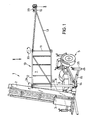
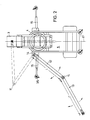
- FIG. 1 shows the lower part of a freight elevator, generally designated 1. It essentially consists of the chassis 5 with the guide rails 2 which are pivotally mounted thereon via a slewing ring 4 (FIG. 2), which are guided telescopically one inside the other and form the guide track for a load platform 3.
- 6 with an indicated energy unit is referred to, which consists of a motor and a hydraulic pump unit for supplying various hydraulic motors, the serve to drive the movement of the guide rails, the load platform and, if necessary, the wheel drive for the short-distance movement at the place of use.
- the loading device 7 can be seen, which consists in its essential components of a support 8 and the boom.
- the boom 10 is divided into two boom sections 12 and 13, which are rotatable on their side in the direction of the arrow 33 about the pivot axis 11 common to them.
- the boom section 12 on the left in the image plane can be pivoted about the support 8, which in turn is mounted in the console in the exemplary embodiment shown in a rotationally fixed manner and is additionally braced via two traction cables 32.
- the console 14 serves to hold a boom support 15, by means of which the chassis 5 can be supported over a wide area on the ground by means of a spindle device 35.
- the boom lengths 1 and 1 ⁇ and the corresponding possible pivot angles are chosen so that the free end 16 of the boom section 13 can be pivoted over the load platform 3.
- pivoting into a stowed position parallel to the longitudinal axis 17 of the chassis is possible as well as into a position in which (see FIG. 3) stacked tiles can be reached by means of the load winch drive 19.
- interlocks 18 are provided, by means of which, according to FIG. 4, the boom section 12 can be locked on the support 8 with respect to its rotational mobility about the support 8.
- the locking device 18 is operated via a Bowden cable 27 which can be actuated by means of a hand lever 28.
- a corresponding locking (see FIG. 3) is provided with respect to the possible pivoting movement of the boom sections 12 and 13 about the axis 11 common to them.
- the locking takes place by means of a Bowden cable 26 and a corresponding hand lever 28.
- a supply line designated 20 is provided, which branches off from the energy unit 6 on the chassis and leads to the load winch drive 19. With 29 a switching strip is designated, by means of which the hydraulic motor of the winch drive 19 can be actuated.
- a gripping device designated 21 - here specifically for the transport of brick stacks 31 - is provided, which has rolling elements 23 provided on a frame 22, which press themselves against the brick stack 31 automatically when the gripper cable 36 is pulled accordingly.
- 10 hollow profiles 24 which have a rectangular cross section are used for the extension arm designed as a truss.
- the arrangement is such that the longer rectangular sides 25 of these hollow profiles 24 run in the horizontal plane.
- the boom section 12 ⁇ is approximately parallelogram-shaped, i.e. the hollow profiles 24 ⁇ and 24 ⁇ (lower and upper chord) extend obliquely upwards from the support 8.
- the second boom section 13 adjoins the first boom section 12 ⁇ , the hollow profile 24 ⁇ of the lower flange of this second boom section being substantially aligned with the hollow profile 24 ⁇ of the first boom section 12 ⁇ .
- the hollow profile 24 ⁇ of the upper chord of the second boom section 13 extends approximately horizontally.
- the first lattice-like boom section 12 ⁇ has diagonal struts 39 and 40 which, at their crossing point 41, clearly project beyond the width b, for example of the hollow profile 24 ⁇ , on both sides.
- a cross member 42 which is arranged in the crossing point 41, serves is firmly welded to an approximately vertical strut 43, so that a substantially higher transverse stability of the first boom section 12 'is achieved.
Landscapes
- Engineering & Computer Science (AREA)
- Structural Engineering (AREA)
- Mechanical Engineering (AREA)
- Civil Engineering (AREA)
- Transportation (AREA)
- Automation & Control Theory (AREA)
- Jib Cranes (AREA)
- Forklifts And Lifting Vehicles (AREA)
- Types And Forms Of Lifts (AREA)
Applications Claiming Priority (4)
| Application Number | Priority Date | Filing Date | Title |
|---|---|---|---|
| DE3628184 | 1986-08-20 | ||
| DE3628184 | 1986-08-20 | ||
| DE19873717352 DE3717352A1 (de) | 1986-08-20 | 1987-05-22 | Mobiler lastaufzug |
| DE3717352 | 1987-05-22 |
Publications (2)
| Publication Number | Publication Date |
|---|---|
| EP0261367A2 true EP0261367A2 (fr) | 1988-03-30 |
| EP0261367A3 EP0261367A3 (fr) | 1988-09-14 |
Family
ID=25846694
Family Applications (1)
| Application Number | Title | Priority Date | Filing Date |
|---|---|---|---|
| EP87111429A Withdrawn EP0261367A3 (fr) | 1986-08-20 | 1987-08-07 | Monte-charge mobile |
Country Status (2)
| Country | Link |
|---|---|
| EP (1) | EP0261367A3 (fr) |
| DE (1) | DE3717352A1 (fr) |
Cited By (2)
| Publication number | Priority date | Publication date | Assignee | Title |
|---|---|---|---|---|
| EP0480893A1 (fr) * | 1990-10-11 | 1992-04-15 | Meccanica Zonzini Di Zonzini Alfonso | Moyens pour rallonger le bras d'un engin de levage à pivotement |
| EP0802151A1 (fr) * | 1996-04-10 | 1997-10-22 | Zasche Fördertechnik GmbH | Flèche pour un appareil de levage |
Family Cites Families (5)
| Publication number | Priority date | Publication date | Assignee | Title |
|---|---|---|---|---|
| DK104198C (da) * | 1960-12-28 | 1966-04-18 | Jacques Tranchero | Kran til anbringelse på undervogne, motorkøretøjer eller traktorer. |
| FR2442781A1 (fr) * | 1978-12-01 | 1980-06-27 | Beaudoing Andre | Appareil de manutention de pieces de type potence |
| GB2136772B (en) * | 1983-03-18 | 1986-08-13 | Annith Engineering Company Lim | Hoist for, e.g., roof tiles |
| DE3430642C2 (de) * | 1984-08-21 | 1987-04-16 | O & K Orenstein & Koppel Ag, 1000 Berlin | Verfahrbarer Schrägaufzug |
| DE3442578A1 (de) * | 1984-11-22 | 1986-06-05 | HAP KRANE GmbH Maschinenfabrik, 2850 Bremerhaven | Be- und entladevorrichtung fuer insbesondere geschlossene lkws |
-
1987
- 1987-05-22 DE DE19873717352 patent/DE3717352A1/de not_active Withdrawn
- 1987-08-07 EP EP87111429A patent/EP0261367A3/fr not_active Withdrawn
Cited By (2)
| Publication number | Priority date | Publication date | Assignee | Title |
|---|---|---|---|---|
| EP0480893A1 (fr) * | 1990-10-11 | 1992-04-15 | Meccanica Zonzini Di Zonzini Alfonso | Moyens pour rallonger le bras d'un engin de levage à pivotement |
| EP0802151A1 (fr) * | 1996-04-10 | 1997-10-22 | Zasche Fördertechnik GmbH | Flèche pour un appareil de levage |
Also Published As
| Publication number | Publication date |
|---|---|
| DE3717352A1 (de) | 1988-04-28 |
| EP0261367A3 (fr) | 1988-09-14 |
Similar Documents
| Publication | Publication Date | Title |
|---|---|---|
| DE2556882A1 (de) | System (anordnung) und verfahren zum selbsttaetigen entstauen und verstauen eines kranauslegers | |
| EP4019452B1 (fr) | Installation de transport des charges permettant de transporter une charge dans un espace de travail | |
| DE3215863C2 (fr) | ||
| EP3212560B1 (fr) | Appareil élévateur à portique pour conteneurs iso | |
| DE3017456A1 (de) | Hochregalstapler | |
| EP2356057A1 (fr) | Pont roulant ou grue à portique pourvue d'un système de rotation et d'un châssis de levage suspendu sous ledit système de rotation | |
| EP0854109A1 (fr) | Appareil pour charger et décharger des navires | |
| DE8422345U1 (de) | Mobiles Hebezeug | |
| EP1365984A2 (fr) | Depot pour conteneurs vides servant au stockage intermediaire de conteneurs vides iso | |
| DE3911868C2 (fr) | ||
| EP0261367A2 (fr) | Monte-charge mobile | |
| DE2811797A1 (de) | Vorrichtung zum verladen von guetern | |
| DE1941940B2 (de) | Fahrzeug mit Hebevorrichtung für großvolumige Kästen, vorzugsweise aus Beton mit Ausnehmungen im Boden für teleskopisch längenveränderliche Beine der Hebevorrichtung | |
| DE60017034T2 (de) | Apparat zum Bewegen von Lasten mit einer mobilen Plattform | |
| DE2647227A1 (de) | Umschlaggeraet zum heben und kippen von frachtcontainern | |
| DE8622268U1 (de) | Mobiler Lastaufzug | |
| DE2735581A1 (de) | Hubeinrichtung fuer fertiggaragen | |
| EP0090949A1 (fr) | Véhicule de transport pour la manutention des conteneurs, particulièrement pour avions | |
| DE2739177A1 (de) | Turm-portalkran | |
| DE3408134A1 (de) | Lastaufzug, insbesondere geruestaufzug mit einem aus mehreren telekopschuessen bestehenden teleskopausleger | |
| DE1756918A1 (de) | Bordeigene Krananlage fuer Container-Schiffe | |
| DE3222510A1 (de) | Transportvorrichtung fuer stapelgut | |
| DE2821102A1 (de) | Fahrzeug, insbesondere kraftfahrzeug, fuer den transport von raumzellen aus stahlbeton, insbesondere fertiggaragen | |
| DE1531208B1 (de) | Betaetigungseinrichtung fuer eine Greifzange eines Tiefofenkrans | |
| DE1813682A1 (de) | Universalhubwagen |
Legal Events
| Date | Code | Title | Description |
|---|---|---|---|
| PUAI | Public reference made under article 153(3) epc to a published international application that has entered the european phase |
Free format text: ORIGINAL CODE: 0009012 |
|
| AK | Designated contracting states |
Kind code of ref document: A2 Designated state(s): AT BE CH DE ES FR GB IT LI LU NL SE |
|
| PUAL | Search report despatched |
Free format text: ORIGINAL CODE: 0009013 |
|
| 17P | Request for examination filed |
Effective date: 19880711 |
|
| AK | Designated contracting states |
Kind code of ref document: A3 Designated state(s): AT BE CH DE ES FR GB IT LI LU NL SE |
|
| 17Q | First examination report despatched |
Effective date: 19890825 |
|
| STAA | Information on the status of an ep patent application or granted ep patent |
Free format text: STATUS: THE APPLICATION HAS BEEN WITHDRAWN |
|
| 18W | Application withdrawn |
Withdrawal date: 19900608 |
|
| RIN1 | Information on inventor provided before grant (corrected) |
Inventor name: BOECKER, ALBERT |