EP0480893A1 - Moyens pour rallonger le bras d'un engin de levage à pivotement - Google Patents
Moyens pour rallonger le bras d'un engin de levage à pivotement Download PDFInfo
- Publication number
- EP0480893A1 EP0480893A1 EP91830425A EP91830425A EP0480893A1 EP 0480893 A1 EP0480893 A1 EP 0480893A1 EP 91830425 A EP91830425 A EP 91830425A EP 91830425 A EP91830425 A EP 91830425A EP 0480893 A1 EP0480893 A1 EP 0480893A1
- Authority
- EP
- European Patent Office
- Prior art keywords
- arm
- swing
- extension
- rope
- coupling
- Prior art date
- Legal status (The legal status is an assumption and is not a legal conclusion. Google has not performed a legal analysis and makes no representation as to the accuracy of the status listed.)
- Withdrawn
Links
- 230000008878 coupling Effects 0.000 claims abstract description 18
- 238000010168 coupling process Methods 0.000 claims abstract description 18
- 238000005859 coupling reaction Methods 0.000 claims abstract description 18
- 230000002787 reinforcement Effects 0.000 claims abstract description 3
- 230000005540 biological transmission Effects 0.000 claims description 4
- 230000000903 blocking effect Effects 0.000 description 1
Images
Classifications
-
- B—PERFORMING OPERATIONS; TRANSPORTING
- B66—HOISTING; LIFTING; HAULING
- B66C—CRANES; LOAD-ENGAGING ELEMENTS OR DEVICES FOR CRANES, CAPSTANS, WINCHES, OR TACKLES
- B66C23/00—Cranes comprising essentially a beam, boom, or triangular structure acting as a cantilever and mounted for translatory of swinging movements in vertical or horizontal planes or a combination of such movements, e.g. jib-cranes, derricks, tower cranes
- B66C23/18—Cranes comprising essentially a beam, boom, or triangular structure acting as a cantilever and mounted for translatory of swinging movements in vertical or horizontal planes or a combination of such movements, e.g. jib-cranes, derricks, tower cranes specially adapted for use in particular purposes
- B66C23/20—Cranes comprising essentially a beam, boom, or triangular structure acting as a cantilever and mounted for translatory of swinging movements in vertical or horizontal planes or a combination of such movements, e.g. jib-cranes, derricks, tower cranes specially adapted for use in particular purposes with supporting couples provided by walls of buildings or like structures
- B66C23/22—Window cranes, i.e. adapted to be supported in window openings
Definitions
- the present patent of invention refers to a swing hoist for lifting loads, which is provided with means for extending the swing hoist arm.
- hoists that, in general, are arranged between the floor and the ceiling of a room and near a window, or even on a balcony, so as to stretch an arm, which is provided with lifting means, out of a parapet of a balcony or a window-sill.
- the above mentioned hoisting apparatuses present an inconvenience, that is when a balcony is not provided with an upper counterceiling, the hoist must be mounted inside the flat and in this case, the arm bearing the lifting motor does not present the features necessary for permitting the hoist itself to be employed when there are intermediate obstacles to overcome.
- the solution of the aforecited problem is proposed by the present invention, which permits a swing hoist to be mounted inside a room looking on to a balcony, this swing hoist being able to get over the door window, directed outwards, and the parapet so as to go out of the balcony itself.
- the device according to the present invention By employing the device according to the present invention, it is still possible to easily lift loads from a balcony, even when the balcony is not provided with an upper clasping support for the swing hoist such as a counterceiling or the like so as to make the loading and unloading of the objects to be shifted vertically easier.
- the invention relates to a swing hoist for lifting loads, which is provided with means for extending its arm, characterized in that the said means consists of a particularly shaped prolongation to be arranged between the fixed support of the swing hoist and the swing arm bearing the motor; the said extension can also co-operate with a perforated tube to be inserted, if necessary, for raising the height of the swing arm in respect of the extension itself; means for mechanically lifting the said arm being also provided.
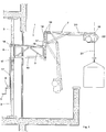
- number 1 indicates a swing hoist according to the invention as a whole, which swing hoist consists in general of a vertical pole 2 comprehending an inner telescopic tube 3 which can be extended by means of a manual small winch 4, operated through a handle 5, till reaching the wished height so as to touch the ceiling.
- a coupling collar 6, adjustable in height, is mounted on the telescopic tube 3.
- An arm 7 for supporting the motor can be directly mounted on the collar 6 in normal conditions of use. In fact, the said arm is provided with holes 8 which can be inserted in projections 9 provided on the coupling collar 6.
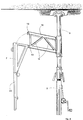
- the swing hoist When it is necessary to prolong the length of the arm itself, the swing hoist must be equipped with an extension 10 so that the swing hoist itself shows for instance a structure as represented in Figg. 1 and 2.
- the extension 10 is in general formed by a parallelepiped-shaped framework, provided with diagonal reinforcements 11 and coupling seats 12 and 13, opposite to each other.
- the first coupling seats 12 have to be inserted in the projections 9 whereas the second ones 13 house the arm 7 and hold the arm itself through its seats 8.
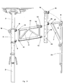
- a perforated tube 14 can be inserted, as shown in Fig. 3.
- the inserted perforated tube 14 consists in general of a structural, provided with a series of longitudinal holes 15 which are to be inserted in the outer coupling seats 13 of the extension 10, and coupling projections 16 which can house the arm 7 through its holes 8.
- the perforated coupling parts 8, 9, 12, 13, 15 and 16, of the arm 7, the collar 6, the extension 10 and the tube 14 respectively can be crossed by pins or the like for blocking a part into another.
- the pole 2 is arranged between a floor and a ceiling by acting on the small winch 4 which draws a rope 17 lifting the telescopic tube 3 through a transmission.
- the arm 7 can be directly mounted on the projections 9 of the collar 6 by centering the holes 8 into the projections 9. Otherwise, in the aforecited particular conditions, the extension 10 is intercalated so as to insert and block the holes 12 of the extension itself in the projections 9.
- the arm 7 is mounted on the extension 10 by inserting the holes 8 in the coupling seats 13.
- the perforated tube 14 can be mounted on the extension 10 by inserting the suitable holes 15 in the coupling seats 13 whereas on the other side, the projections 16 can house the holes 8 of the arm 7.
- the arm 7 without the lifting group 18 can be mounted on the relative supports with a particular kind of lifting by means of a further rope 17′, moved through the same winch 4.
- the small winch 4 has the double function of raising the telescopic tube 3 towards the ceiling by means of the rope 17 and raising the arm 7 and its operating means through the rope 17′.
- the small winch 4 operates the drawing of the rope 17′ which is fixed on the motor 18 when the motor is still in its container.
- the motor By acting on the same handle 5, the motor recovers the space of the telescopic part 20 of the arm 7, the telescopic part 20 being operated by an inner pressure spring.
- the motor When the motor has closed the telescopic space, the arm begins to raise till inserting the upper point 8 in one of the coupling parts 9, 13 or 16. The whole is locked by means of pins or the like.
- the telescopic part 20 can be moved inside or outside the arm in opposition with the pressed spring by reversing the direction of rotation of the small winch 4 and acting on the handle 5.
- the motor 18 is driven electrically through a push-button panel "rise-descent" and comprises a lifting rope 21 which can be rewinded on a drum 22 arranged on a horizontal axis.
- a drum comprises lips of transmission which permit a good rewinding and unwinding of the rope 21 itself.
Landscapes
- Engineering & Computer Science (AREA)
- Civil Engineering (AREA)
- Structural Engineering (AREA)
- Mechanical Engineering (AREA)
- Movable Scaffolding (AREA)
- Electric Cable Installation (AREA)
- Jib Cranes (AREA)
Applications Claiming Priority (2)
| Application Number | Priority Date | Filing Date | Title |
|---|---|---|---|
| IT8500590 | 1990-10-11 | ||
| IT08500590A IT1243604B (it) | 1990-10-11 | 1990-10-11 | Mezzi per il prolungamento del braccio di un ponteggio per il sollevamento di carichi |
Publications (1)
| Publication Number | Publication Date |
|---|---|
| EP0480893A1 true EP0480893A1 (fr) | 1992-04-15 |
Family
ID=11326906
Family Applications (1)
| Application Number | Title | Priority Date | Filing Date |
|---|---|---|---|
| EP91830425A Withdrawn EP0480893A1 (fr) | 1990-10-11 | 1991-10-09 | Moyens pour rallonger le bras d'un engin de levage à pivotement |
Country Status (2)
| Country | Link |
|---|---|
| EP (1) | EP0480893A1 (fr) |
| IT (1) | IT1243604B (fr) |
Cited By (3)
| Publication number | Priority date | Publication date | Assignee | Title |
|---|---|---|---|---|
| NL1034560C2 (nl) * | 2007-10-21 | 2009-04-22 | Hendrik Heerema | Tilinrichting. |
| CN108249367A (zh) * | 2017-12-04 | 2018-07-06 | 淮阴工学院 | 可拆卸组合便携式室内简易举升装置 |
| CN112010196A (zh) * | 2020-08-24 | 2020-12-01 | 陈和东 | 一种高层建筑安装或拆卸空调外机吊运装置 |
Families Citing this family (1)
| Publication number | Priority date | Publication date | Assignee | Title |
|---|---|---|---|---|
| CN111994804B (zh) * | 2020-08-24 | 2022-12-20 | 北京承达智能科技有限公司 | 用于高层建筑墙外安装空调外机的吊运方法 |
Citations (8)
| Publication number | Priority date | Publication date | Assignee | Title |
|---|---|---|---|---|
| FR640831A (fr) * | 1927-02-19 | 1928-07-23 | Grue gerbeuse | |
| CH304484A (de) * | 1952-04-15 | 1955-01-15 | Soehne Joseph Wormser | An Fensteröffnungen anbringbare Aufzugsvorrichtung. |
| FR1365378A (fr) * | 1963-05-14 | 1964-07-03 | Potence à bras articulés orientables dans un plan horizontal | |
| DE3024618A1 (de) * | 1980-06-30 | 1982-01-28 | Fa. Walter Vom Brocke, 5630 Remscheid | Vorrichtung zum heben und senken von lasten |
| EP0261367A2 (fr) * | 1986-08-20 | 1988-03-30 | Albert Böcker GmbH & Co. KG | Monte-charge mobile |
| GB2209322A (en) * | 1987-09-02 | 1989-05-10 | British Petroleum Co Plc | Folding boom |
| DE3806599C1 (en) * | 1988-03-02 | 1989-09-21 | Helmut Kempkes Gmbh, 5630 Remscheid, De | Building crane |
| DE3808121A1 (de) * | 1988-03-11 | 1989-09-21 | Wilfried Baeder | Handhabungsgeraet zum greifen und bewegen von gegenstaenden |
-
1990
- 1990-10-11 IT IT08500590A patent/IT1243604B/it active IP Right Grant
-
1991
- 1991-10-09 EP EP91830425A patent/EP0480893A1/fr not_active Withdrawn
Patent Citations (8)
| Publication number | Priority date | Publication date | Assignee | Title |
|---|---|---|---|---|
| FR640831A (fr) * | 1927-02-19 | 1928-07-23 | Grue gerbeuse | |
| CH304484A (de) * | 1952-04-15 | 1955-01-15 | Soehne Joseph Wormser | An Fensteröffnungen anbringbare Aufzugsvorrichtung. |
| FR1365378A (fr) * | 1963-05-14 | 1964-07-03 | Potence à bras articulés orientables dans un plan horizontal | |
| DE3024618A1 (de) * | 1980-06-30 | 1982-01-28 | Fa. Walter Vom Brocke, 5630 Remscheid | Vorrichtung zum heben und senken von lasten |
| EP0261367A2 (fr) * | 1986-08-20 | 1988-03-30 | Albert Böcker GmbH & Co. KG | Monte-charge mobile |
| GB2209322A (en) * | 1987-09-02 | 1989-05-10 | British Petroleum Co Plc | Folding boom |
| DE3806599C1 (en) * | 1988-03-02 | 1989-09-21 | Helmut Kempkes Gmbh, 5630 Remscheid, De | Building crane |
| DE3808121A1 (de) * | 1988-03-11 | 1989-09-21 | Wilfried Baeder | Handhabungsgeraet zum greifen und bewegen von gegenstaenden |
Cited By (4)
| Publication number | Priority date | Publication date | Assignee | Title |
|---|---|---|---|---|
| NL1034560C2 (nl) * | 2007-10-21 | 2009-04-22 | Hendrik Heerema | Tilinrichting. |
| CN108249367A (zh) * | 2017-12-04 | 2018-07-06 | 淮阴工学院 | 可拆卸组合便携式室内简易举升装置 |
| CN112010196A (zh) * | 2020-08-24 | 2020-12-01 | 陈和东 | 一种高层建筑安装或拆卸空调外机吊运装置 |
| CN112010196B (zh) * | 2020-08-24 | 2023-01-20 | 安徽平天湖投资控股集团有限公司 | 一种高层建筑安装或拆卸空调外机吊运装置 |
Also Published As
| Publication number | Publication date |
|---|---|
| IT9085005A1 (it) | 1992-04-11 |
| IT1243604B (it) | 1994-06-16 |
| IT9085005A0 (it) | 1990-10-11 |
Similar Documents
| Publication | Publication Date | Title |
|---|---|---|
| US5535852A (en) | Lift apparatus | |
| US6237781B1 (en) | Device for elevating articles for storage within a garage | |
| US6234453B1 (en) | Rolling door winch apparatus | |
| US5078364A (en) | Carriage lock mechanism for portable cable hoist | |
| US3679174A (en) | Jack or lift mechanism and drive therefor | |
| US3983584A (en) | Vehicle invalid lift device | |
| EP0480893A1 (fr) | Moyens pour rallonger le bras d'un engin de levage à pivotement | |
| NO119062B (fr) | ||
| JPH07206366A (ja) | ドラム缶の吊り装置 | |
| US2018568A (en) | Hoist | |
| JPH04166555A (ja) | 可動式天井収納庫 | |
| KR20220051992A (ko) | 차량용 캐빈 | |
| JPH1077198A (ja) | 荷揚機 | |
| KR102001905B1 (ko) | 엘리베이터용 상하개폐식 도어의 구동시스템 | |
| US20060255701A1 (en) | Storage cabinet | |
| JP2935585B2 (ja) | 移動作業台の昇降作動制御装置 | |
| JP4426818B2 (ja) | 手動昇降の床下収納装置 | |
| US20240270541A1 (en) | Balcony hoist | |
| CN214826097U (zh) | 一种新型物料提升机用吊笼 | |
| JPH04191276A (ja) | エレベータ装置 | |
| JPH10203792A (ja) | 床下昇降装置 | |
| CN217894906U (zh) | 一种挂钩和高孔阀孔板提升装置 | |
| JPS6251880A (ja) | プロジエクタ装置の昇降装置 | |
| SU1423487A1 (ru) | Строительный подъемник | |
| JPH08192993A (ja) | トラック用簡易型クレーン |
Legal Events
| Date | Code | Title | Description |
|---|---|---|---|
| PUAI | Public reference made under article 153(3) epc to a published international application that has entered the european phase |
Free format text: ORIGINAL CODE: 0009012 |
|
| AK | Designated contracting states |
Kind code of ref document: A1 Designated state(s): AT CH DE ES FR LI |
|
| STAA | Information on the status of an ep patent application or granted ep patent |
Free format text: STATUS: THE APPLICATION IS DEEMED TO BE WITHDRAWN |
|
| 18D | Application deemed to be withdrawn |
Effective date: 19921016 |