EP0261480A2 - Stufenloses Reibungsrollengetriebe mit hydraulischer Steuerung - Google Patents
Stufenloses Reibungsrollengetriebe mit hydraulischer Steuerung Download PDFInfo
- Publication number
- EP0261480A2 EP0261480A2 EP87112954A EP87112954A EP0261480A2 EP 0261480 A2 EP0261480 A2 EP 0261480A2 EP 87112954 A EP87112954 A EP 87112954A EP 87112954 A EP87112954 A EP 87112954A EP 0261480 A2 EP0261480 A2 EP 0261480A2
- Authority
- EP
- European Patent Office
- Prior art keywords
- traction
- roller
- support member
- traction roller
- toric
- Prior art date
- Legal status (The legal status is an assumption and is not a legal conclusion. Google has not performed a legal analysis and makes no representation as to the accuracy of the status listed.)
- Granted
Links
- 230000005540 biological transmission Effects 0.000 title claims abstract description 42
- 230000002706 hydrostatic effect Effects 0.000 claims abstract description 17
- 230000033001 locomotion Effects 0.000 claims abstract description 15
- 239000012530 fluid Substances 0.000 claims description 15
- 230000000977 initiatory effect Effects 0.000 claims description 2
- 241001052209 Cylinder Species 0.000 description 1
- 238000005452 bending Methods 0.000 description 1
- 238000013270 controlled release Methods 0.000 description 1
- 230000010355 oscillation Effects 0.000 description 1
- 229920000136 polysorbate Polymers 0.000 description 1
Images

Classifications
-
- F—MECHANICAL ENGINEERING; LIGHTING; HEATING; WEAPONS; BLASTING
- F16—ENGINEERING ELEMENTS AND UNITS; GENERAL MEASURES FOR PRODUCING AND MAINTAINING EFFECTIVE FUNCTIONING OF MACHINES OR INSTALLATIONS; THERMAL INSULATION IN GENERAL
- F16H—GEARING
- F16H15/00—Gearings for conveying rotary motion with variable gear ratio, or for reversing rotary motion, by friction between rotary members
- F16H15/02—Gearings for conveying rotary motion with variable gear ratio, or for reversing rotary motion, by friction between rotary members without members having orbital motion
- F16H15/04—Gearings providing a continuous range of gear ratios
- F16H15/06—Gearings providing a continuous range of gear ratios in which a member A of uniform effective diameter mounted on a shaft may co-operate with different parts of a member B
- F16H15/32—Gearings providing a continuous range of gear ratios in which a member A of uniform effective diameter mounted on a shaft may co-operate with different parts of a member B in which the member B has a curved friction surface formed as a surface of a body of revolution generated by a curve which is neither a circular arc centered on its axis of revolution nor a straight line
- F16H15/36—Gearings providing a continuous range of gear ratios in which a member A of uniform effective diameter mounted on a shaft may co-operate with different parts of a member B in which the member B has a curved friction surface formed as a surface of a body of revolution generated by a curve which is neither a circular arc centered on its axis of revolution nor a straight line with concave friction surface, e.g. a hollow toroid surface
- F16H15/38—Gearings providing a continuous range of gear ratios in which a member A of uniform effective diameter mounted on a shaft may co-operate with different parts of a member B in which the member B has a curved friction surface formed as a surface of a body of revolution generated by a curve which is neither a circular arc centered on its axis of revolution nor a straight line with concave friction surface, e.g. a hollow toroid surface with two members B having hollow toroid surfaces opposite to each other, the member or members A being adjustably mounted between the surfaces
Definitions
- the invention relates to an infinitely variable traction roller transmission in which power is transmitted through traction rollers pivotally supported in a housing between toric input and outut discs.
- the traction rollers are mounted on support structures which, when pivoted, cause engagement of the traction rollers with the toric discs in circles of varying diameters depending on the desired transmission ratio.
- the pivotal traction rollers are so supported that they can be moved axially for initiating a change in the transmission ratio.
- two traction rollers may be supported opposite one another by flexible tension sheets as shown in U.S. Patent 4,086,820 which issued May 2, 1978 to Charles E. Kraus.
- the present invention resides in an infinitely variable traction roller transmission comprising a housing; coaxial input and output shafts rotatably supported in said housing; two toric traction discs supported opposite each other, one by said input and the other by said output shaft, said toric discs having opposite toric traction surfaces defining therebetween a toric cavity of circular cross-section; at least two motion transmitting traction rollers arranged in said toric cavity in radial symmetry and in engagement with said toric discs for the transmis sion of motion therebetween, each of said traction rollers being rotatably supported in said housing by a support structure including a pivotal support member supported in said housing pivotally about an axis which is tangential to the center circle of said toric cavity and a roller support member rotatably supporting said traction roller and being supported on said pivotal support member by a hydrostatic bearing structure adapted to force said traction roller into firm engagement with said traction discs, the pivotal support member of each of said traction roller support structures has gear
- traction rollers disposed at 90° intervals and the gear segments are mounted on the opposite ends of each support member and have bevel gear structures in meshing engagement for transmission ratio changing pivot movement of all four traction rollers in unison.
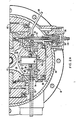
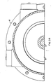
- a traction roller transmission as shown in Fig. 1 consists of a housing 10 having coaxial input and out-put shafts 12 and 14 rotatably supported therein by bearings 16 and 18. Associated with the input and output shafts 12 and 14 are toric traction discs 20 and 22 which are so arranged opposite each other that a toric cavity 24 of circular cross-section is defined therebetween. Within the toric cavity 24 traction rollers 26, 28, 30 and 32 (see also Fig. 2) are rotatably supported and are in engagement with the toric traction discs 20 and 22 for the transmission of motion between the discs 20 and 22.
- rollers 26, 28, 30 and 32 are supported in the housing 10 by a pivotal support member 34 which is disposed on a pivot base 36 mounted in, or formed integral with, the housing 10 behind each pivotal support member 34.
- a hydrostatic support bearing as shown, for example, in U.S. Patent 4,576,055 is formed, or antifriction bearing segments 38 are disposed, between the pivotal support member 34 and the pivot base 36 to faciliate pivoting of the pivotal support member 34 on the pivot base 36 for the setting of different transmission ratios.
- the roller support member 40 is floatingly supported on a pivotal support member 34 during operating of the transmission by a pressurized hydraulic fluid supplied to a hydrostatic support bearing structure 42 formed between the roller support member 40 and the pivotal support member 43.
- the roller support member 40 carries a shaft stud 44 on which the traction roller 30 is rotatably supported by way of a needle bearing 46. Between the roller support member 40 and the roller 30 there is provided a hydrostatic axial thrust bearing structure 48 as well as an auxiliary antifriction bearing 50 adapted to prevent damage to the traction rollers when they are rotated without sufficient hydrostatic fluid in the hydrostatic axial thrust bearing 48.
- Pressurized fluid is supplied to the support bearing structure 42 by means of a hollow push rod 52 which is connected at one end to the roller support member 40 and has a control piston 54 disposed at its other end, the piston 54 being movable in a cylinder 56 mounted on the housing 10.
- the support member 40 is floatingly supported on the pivotal support 34 by the pressurized fluid in the hydrostatic bearing 42 so that the support member 40 is easily movable on the flat surface 43 of the support 34 by the control piston 54 to provide for precess movement of the roller 30 for changing the transmission ratio.
- Pressurized fluid is supplied to the cylinder cavity 58 through inlet 60, the pressure of the fluid being variable depending on the torque being transmitted through the transmission.
- a return spring 62 is provided on the opposite side of the piston 54 to return the piston to a normal non-precess position when, after application of an increased pressure, the transmission ratio has changed and the corresponding greater reaction torque forces are being compensated for.
- a check valve 64 may be provided in the passage through the push rod 52 to prevent rapid pressure and force oscillations thereby providing only for flow to the bearing 42. Controlled release flow is provided for by a bleed orifice 66. The pressure in the bearing 42 accordingly depends on the torque transmitted through the transmission and the traction roller 30 is forced into engagement with the traction discs only with the force as required for the transmission of the respective torque.
- a control arrangement for providing fluid of the adequate pressure is described for example in applicant's U.S.
- Fluid supply to the hydrostatic axial thrust bearing 48 is independent, a measured flow of high pressure fluid being utilized for this bearing as it is common for limited leakage seal type axial thrust bearings.
- the fluid is supplied to the bearing 48 by way of a supply line 58 which includes a ring line 70 around the push rod 52.
- the supply line 68 also includes a slide connection 72 to accommodate the movements of the support member 40.
- a flexible pressure hose connection may be provided. Both fluid supplies, the push rod 52 and the line 68, are arranged in the pivot axis of the traction roller and its support structure, that is, they are coincident with the axis of rotation of the bearing sections 38.
- gear segments 74 which are mounted to the sides of the pivotal support members and are provided with a bevel gear structure 76 which is in engagement with the bevel gear structure of the gear segments of the pivotal support members of the adjacent rollers.
- gear segments 74 which are mounted to the sides of the pivotal support members and are provided with a bevel gear structure 76 which is in engagement with the bevel gear structure of the gear segments of the pivotal support members of the adjacent rollers.
- four traction rollers and the respective support structure are utilized. With the relative sizes as shown, four traction rollers provide for about full utilization of the toroidal space between the toric traction discs. However, three traction rollers may be utilized with the respective gear segments of each roller support structure in engagement with those of the two adjacent roller support structures.
- the gear interfacing of the roller support structures is possible because the traction roller support structure is not radially movable relative to the housing, that is, relative to the adjacent traction roller support structures but only pivotable together with the adjacent support structures. Only the roller support member 40 together with the roller 30, that is, all the rollers 26-32, are movable toward the center of the transmission for firm engagement of the traction rollers with the traction discs. Since the support of the roller support members is by a pressurized fluid, vibrations of the roller are only vaguely transmitted to the pivotal support member 34 and the gear segments 74.
- the hydrostatic support bearing structure 42 for the roller support member 40 is formed somwhat off-center to compensate for the torque forces generated during power transmission of the rollers since the traction forces are applied in a plane defined by the circle of contact of the traction roller with the traction discs and the control piston forces are effective along the pivot axis of the traction roller which are spaced somewhat from the plane of the traction rollers contact circle.
Landscapes
- Engineering & Computer Science (AREA)
- General Engineering & Computer Science (AREA)
- Mechanical Engineering (AREA)
- Friction Gearing (AREA)
Applications Claiming Priority (2)
| Application Number | Priority Date | Filing Date | Title |
|---|---|---|---|
| US06/909,882 US4702118A (en) | 1986-09-22 | 1986-09-22 | Hydraulically controlled infinitely variable traction roller transmission |
| US909882 | 1986-09-22 |
Publications (3)
| Publication Number | Publication Date |
|---|---|
| EP0261480A2 true EP0261480A2 (de) | 1988-03-30 |
| EP0261480A3 EP0261480A3 (en) | 1988-12-21 |
| EP0261480B1 EP0261480B1 (de) | 1991-04-10 |
Family
ID=25427977
Family Applications (1)
| Application Number | Title | Priority Date | Filing Date |
|---|---|---|---|
| EP87112954A Expired EP0261480B1 (de) | 1986-09-22 | 1987-09-04 | Stufenloses Reibungsrollengetriebe mit hydraulischer Steuerung |
Country Status (3)
| Country | Link |
|---|---|
| US (1) | US4702118A (de) |
| EP (1) | EP0261480B1 (de) |
| DE (1) | DE3769256D1 (de) |
Families Citing this family (11)
| Publication number | Priority date | Publication date | Assignee | Title |
|---|---|---|---|---|
| JPS63130954A (ja) * | 1986-11-20 | 1988-06-03 | Nissan Motor Co Ltd | 摩擦車式無段変速機構 |
| US4858484A (en) * | 1987-10-26 | 1989-08-22 | Excelermatic Inc. | Infinitely variable traction roller transmission |
| JPH0637223Y2 (ja) * | 1988-05-27 | 1994-09-28 | 日産自動車株式会社 | 摩擦車式無段変速機構 |
| US4964312A (en) * | 1988-10-17 | 1990-10-23 | Excelermatic Inc. | Infinitely variable traction roller transmission |
| US5020384A (en) * | 1988-10-17 | 1991-06-04 | Excelermatic Inc. | Infinitely variable traction roller transmission |
| US4911030A (en) * | 1989-01-30 | 1990-03-27 | Excelermatic Inc. | Traction roller transmission ratio control arrangement |
| US4885955A (en) * | 1989-03-27 | 1989-12-12 | Excelermatic Inc. | Multimode infinitely variable transmission |
| US5085089A (en) * | 1991-02-06 | 1992-02-04 | Excelermatic Inc. | Infinitely variable traction roller transmission |
| US5330396A (en) * | 1992-12-16 | 1994-07-19 | The Torax Company, Inc. | Loading device for continuously variable transmission |
| US5540631A (en) * | 1992-12-16 | 1996-07-30 | The Torax Company, Inc. | Continuously variable transmission with a hydraulic control system |
| US5299987A (en) * | 1993-04-08 | 1994-04-05 | Exceleramatic Inc. | Infinitely variable traction roller transmission |
Family Cites Families (14)
| Publication number | Priority date | Publication date | Assignee | Title |
|---|---|---|---|---|
| US751958A (en) * | 1904-02-09 | Variable-speed device | ||
| US1853749A (en) * | 1928-12-11 | 1932-04-12 | John S Sharpe | Transmission |
| US2903897A (en) * | 1957-09-27 | 1959-09-15 | James W Whalen | Variable drive transmission |
| NL290855A (de) * | 1961-03-08 | |||
| US3163051A (en) * | 1963-06-19 | 1964-12-29 | Excelermatic | Roller construction for toroidal transmissions |
| US3163050A (en) * | 1963-06-19 | 1964-12-29 | Excelermatic | Toroidal transmission bearing means |
| US3486391A (en) * | 1968-09-19 | 1969-12-30 | Excelermatic | Toroidal type transmission |
| US3828618A (en) * | 1971-07-27 | 1974-08-13 | Rotax Ltd | Constant speed hydraulically controlled toric transmission with concentric, two piston valve, governor and constant ratio means |
| US4086820A (en) * | 1976-06-25 | 1978-05-02 | Excelermatic, Inc. | Infinitely variable traction roller transmission |
| US4501172A (en) * | 1982-08-16 | 1985-02-26 | Excelermatic Inc. | Hydraulic speed control arrangement for an infinitely variable transmission |
| US4484487A (en) * | 1983-01-03 | 1984-11-27 | Excelermatic Inc. | Hydraulically controlled infinitely variable traction roller transmission |
| US4464946A (en) * | 1983-01-26 | 1984-08-14 | Excelermatic Inc. | Control arrangement for the supply of lubricant to the bearings of an infinitely variable traction roller transmission |
| US4526051A (en) * | 1983-03-18 | 1985-07-02 | Excelermatic Inc. | Infinitely variable traction roller transmission speed control arrangement |
| US4576055A (en) * | 1984-08-15 | 1986-03-18 | Excelermatic, Inc. | Hydraulically controlled infinitely variable traction roller transmission |
-
1986
- 1986-09-22 US US06/909,882 patent/US4702118A/en not_active Expired - Fee Related
-
1987
- 1987-09-04 DE DE8787112954T patent/DE3769256D1/de not_active Expired - Fee Related
- 1987-09-04 EP EP87112954A patent/EP0261480B1/de not_active Expired
Also Published As
| Publication number | Publication date |
|---|---|
| EP0261480B1 (de) | 1991-04-10 |
| US4702118A (en) | 1987-10-27 |
| EP0261480A3 (en) | 1988-12-21 |
| DE3769256D1 (de) | 1991-05-16 |
Similar Documents
| Publication | Publication Date | Title |
|---|---|---|
| EP0365872B1 (de) | Stufenloses Reibrad-Getriebe | |
| US5020384A (en) | Infinitely variable traction roller transmission | |
| EP0261480A2 (de) | Stufenloses Reibungsrollengetriebe mit hydraulischer Steuerung | |
| US4576055A (en) | Hydraulically controlled infinitely variable traction roller transmission | |
| EP0413342B1 (de) | Stufenloses Toroidalgetriebe | |
| US4484487A (en) | Hydraulically controlled infinitely variable traction roller transmission | |
| KR20070102615A (ko) | 무한 가변 변속기용 구동 기구 | |
| EP1486700B1 (de) | Reibrad und Lageranordnung für ein stufenloses Reibradgetriebe | |
| US4112780A (en) | Variable speed transmission device | |
| EP0380933B1 (de) | Steuerungssystem für ein Triebrollengetriebe | |
| EP0400187B1 (de) | Stufenloses Reibrollengetriebe | |
| US4694704A (en) | Infinitely variable traction roller transmission | |
| US4434676A (en) | Traction roller transmission with mechanical transmission ratio control | |
| US3837233A (en) | Continuously variable friction drive having intermediate member engaged on both sides for increased torque transmission | |
| US5045037A (en) | Friction stepless speed change device | |
| US5030183A (en) | Friction stepless speed change device | |
| EP0637705B1 (de) | Stufenlos verstellbares Reibrollengetriebe | |
| EP0425914A2 (de) | Stufenloses Reibrollengetriebe | |
| JP3480034B2 (ja) | トロイダル型無段変速機 | |
| EP0486191A1 (de) | Stufenloses Reibungsgetriebe ohne Kontaktschwenkung | |
| EP0366848A2 (de) | Getriebbe mit stufenlos veränderbarer Übersetzung | |
| US4745821A (en) | Speed ratio adjusting system for nutational traction drive transmissions | |
| EP1270998A2 (de) | Stufenloses Toroidalgetriebe | |
| EP0210231B1 (de) | Radial ausgerichtetes nutationsfriktionsgetriebe | |
| JP3538227B2 (ja) | 無段牽引ローラ変速機 |
Legal Events
| Date | Code | Title | Description |
|---|---|---|---|
| PUAI | Public reference made under article 153(3) epc to a published international application that has entered the european phase |
Free format text: ORIGINAL CODE: 0009012 |
|
| AK | Designated contracting states |
Kind code of ref document: A2 Designated state(s): DE FR GB IT SE |
|
| PUAL | Search report despatched |
Free format text: ORIGINAL CODE: 0009013 |
|
| AK | Designated contracting states |
Kind code of ref document: A3 Designated state(s): DE FR GB IT SE |
|
| 17P | Request for examination filed |
Effective date: 19890524 |
|
| 17Q | First examination report despatched |
Effective date: 19900129 |
|
| 17Q | First examination report despatched |
Effective date: 19900712 |
|
| GRAA | (expected) grant |
Free format text: ORIGINAL CODE: 0009210 |
|
| ITF | It: translation for a ep patent filed | ||
| AK | Designated contracting states |
Kind code of ref document: B1 Designated state(s): DE FR GB IT SE |
|
| PG25 | Lapsed in a contracting state [announced via postgrant information from national office to epo] |
Ref country code: SE Effective date: 19910410 |
|
| REF | Corresponds to: |
Ref document number: 3769256 Country of ref document: DE Date of ref document: 19910516 |
|
| ET | Fr: translation filed | ||
| PLBE | No opposition filed within time limit |
Free format text: ORIGINAL CODE: 0009261 |
|
| STAA | Information on the status of an ep patent application or granted ep patent |
Free format text: STATUS: NO OPPOSITION FILED WITHIN TIME LIMIT |
|
| 26N | No opposition filed | ||
| PGFP | Annual fee paid to national office [announced via postgrant information from national office to epo] |
Ref country code: FR Payment date: 19970826 Year of fee payment: 11 |
|
| PGFP | Annual fee paid to national office [announced via postgrant information from national office to epo] |
Ref country code: GB Payment date: 19970902 Year of fee payment: 11 |
|
| PG25 | Lapsed in a contracting state [announced via postgrant information from national office to epo] |
Ref country code: GB Free format text: LAPSE BECAUSE OF NON-PAYMENT OF DUE FEES Effective date: 19980904 |
|
| GBPC | Gb: european patent ceased through non-payment of renewal fee |
Effective date: 19980904 |
|
| PG25 | Lapsed in a contracting state [announced via postgrant information from national office to epo] |
Ref country code: FR Free format text: LAPSE BECAUSE OF NON-PAYMENT OF DUE FEES Effective date: 19990531 |
|
| REG | Reference to a national code |
Ref country code: FR Ref legal event code: ST |
|
| PGFP | Annual fee paid to national office [announced via postgrant information from national office to epo] |
Ref country code: DE Payment date: 19990918 Year of fee payment: 13 |
|
| PG25 | Lapsed in a contracting state [announced via postgrant information from national office to epo] |
Ref country code: DE Free format text: LAPSE BECAUSE OF NON-PAYMENT OF DUE FEES Effective date: 20010601 |
|
| PG25 | Lapsed in a contracting state [announced via postgrant information from national office to epo] |
Ref country code: IT Free format text: LAPSE BECAUSE OF NON-PAYMENT OF DUE FEES;WARNING: LAPSES OF ITALIAN PATENTS WITH EFFECTIVE DATE BEFORE 2007 MAY HAVE OCCURRED AT ANY TIME BEFORE 2007. THE CORRECT EFFECTIVE DATE MAY BE DIFFERENT FROM THE ONE RECORDED. Effective date: 20050904 |