EP0365872B1 - Stufenloses Reibrad-Getriebe - Google Patents
Stufenloses Reibrad-Getriebe Download PDFInfo
- Publication number
- EP0365872B1 EP0365872B1 EP89118275A EP89118275A EP0365872B1 EP 0365872 B1 EP0365872 B1 EP 0365872B1 EP 89118275 A EP89118275 A EP 89118275A EP 89118275 A EP89118275 A EP 89118275A EP 0365872 B1 EP0365872 B1 EP 0365872B1
- Authority
- EP
- European Patent Office
- Prior art keywords
- toric
- trunnions
- pivot
- traction
- transmission
- Prior art date
- Legal status (The legal status is an assumption and is not a legal conclusion. Google has not performed a legal analysis and makes no representation as to the accuracy of the status listed.)
- Expired - Lifetime
Links
- 230000005540 biological transmission Effects 0.000 title claims description 78
- 230000007246 mechanism Effects 0.000 claims description 11
- 230000033001 locomotion Effects 0.000 claims description 9
- 230000000977 initiatory effect Effects 0.000 claims description 3
- 230000008878 coupling Effects 0.000 claims 1
- 238000010168 coupling process Methods 0.000 claims 1
- 238000005859 coupling reaction Methods 0.000 claims 1
- 239000012530 fluid Substances 0.000 description 6
- 239000002184 metal Substances 0.000 description 2
- 230000006835 compression Effects 0.000 description 1
- 238000007906 compression Methods 0.000 description 1
- 230000036316 preload Effects 0.000 description 1
Images



Classifications
-
- F—MECHANICAL ENGINEERING; LIGHTING; HEATING; WEAPONS; BLASTING
- F16—ENGINEERING ELEMENTS AND UNITS; GENERAL MEASURES FOR PRODUCING AND MAINTAINING EFFECTIVE FUNCTIONING OF MACHINES OR INSTALLATIONS; THERMAL INSULATION IN GENERAL
- F16H—GEARING
- F16H15/00—Gearings for conveying rotary motion with variable gear ratio, or for reversing rotary motion, by friction between rotary members
- F16H15/02—Gearings for conveying rotary motion with variable gear ratio, or for reversing rotary motion, by friction between rotary members without members having orbital motion
- F16H15/04—Gearings providing a continuous range of gear ratios
- F16H15/06—Gearings providing a continuous range of gear ratios in which a member A of uniform effective diameter mounted on a shaft may co-operate with different parts of a member B
- F16H15/32—Gearings providing a continuous range of gear ratios in which a member A of uniform effective diameter mounted on a shaft may co-operate with different parts of a member B in which the member B has a curved friction surface formed as a surface of a body of revolution generated by a curve which is neither a circular arc centered on its axis of revolution nor a straight line
- F16H15/36—Gearings providing a continuous range of gear ratios in which a member A of uniform effective diameter mounted on a shaft may co-operate with different parts of a member B in which the member B has a curved friction surface formed as a surface of a body of revolution generated by a curve which is neither a circular arc centered on its axis of revolution nor a straight line with concave friction surface, e.g. a hollow toroid surface
- F16H15/38—Gearings providing a continuous range of gear ratios in which a member A of uniform effective diameter mounted on a shaft may co-operate with different parts of a member B in which the member B has a curved friction surface formed as a surface of a body of revolution generated by a curve which is neither a circular arc centered on its axis of revolution nor a straight line with concave friction surface, e.g. a hollow toroid surface with two members B having hollow toroid surfaces opposite to each other, the member or members A being adjustably mounted between the surfaces
-
- F—MECHANICAL ENGINEERING; LIGHTING; HEATING; WEAPONS; BLASTING
- F16—ENGINEERING ELEMENTS AND UNITS; GENERAL MEASURES FOR PRODUCING AND MAINTAINING EFFECTIVE FUNCTIONING OF MACHINES OR INSTALLATIONS; THERMAL INSULATION IN GENERAL
- F16H—GEARING
- F16H15/00—Gearings for conveying rotary motion with variable gear ratio, or for reversing rotary motion, by friction between rotary members
- F16H15/02—Gearings for conveying rotary motion with variable gear ratio, or for reversing rotary motion, by friction between rotary members without members having orbital motion
- F16H15/04—Gearings providing a continuous range of gear ratios
- F16H15/06—Gearings providing a continuous range of gear ratios in which a member A of uniform effective diameter mounted on a shaft may co-operate with different parts of a member B
- F16H15/32—Gearings providing a continuous range of gear ratios in which a member A of uniform effective diameter mounted on a shaft may co-operate with different parts of a member B in which the member B has a curved friction surface formed as a surface of a body of revolution generated by a curve which is neither a circular arc centered on its axis of revolution nor a straight line
- F16H15/36—Gearings providing a continuous range of gear ratios in which a member A of uniform effective diameter mounted on a shaft may co-operate with different parts of a member B in which the member B has a curved friction surface formed as a surface of a body of revolution generated by a curve which is neither a circular arc centered on its axis of revolution nor a straight line with concave friction surface, e.g. a hollow toroid surface
- F16H15/38—Gearings providing a continuous range of gear ratios in which a member A of uniform effective diameter mounted on a shaft may co-operate with different parts of a member B in which the member B has a curved friction surface formed as a surface of a body of revolution generated by a curve which is neither a circular arc centered on its axis of revolution nor a straight line with concave friction surface, e.g. a hollow toroid surface with two members B having hollow toroid surfaces opposite to each other, the member or members A being adjustably mounted between the surfaces
- F16H2015/383—Gearings providing a continuous range of gear ratios in which a member A of uniform effective diameter mounted on a shaft may co-operate with different parts of a member B in which the member B has a curved friction surface formed as a surface of a body of revolution generated by a curve which is neither a circular arc centered on its axis of revolution nor a straight line with concave friction surface, e.g. a hollow toroid surface with two members B having hollow toroid surfaces opposite to each other, the member or members A being adjustably mounted between the surfaces with two or more sets of toroid gearings arranged in parallel
Definitions
- the invention relates to an infinitely variable traction roller transmission in which power is transmitted through traction rollers pivotally supported in a housing between toric input and output discs.
- the traction rollers are mounted on support structures which, when pivoted, cause engagement of the traction rollers with the toric discs in circles of varying diameters depending on the desired transmission ratio.
- the pivotal traction roller support structures are so supported that they can be moved axially for initiating a change in the transmission ratio.
- two traction rollers may be supported opposite one another by flexible tension sheets as shown in the generic US-A 4,086,820.
- the traction roller support members are pivotally supported with respect to the transmission housing by means of antifriction bearing segments which are disposed at opposite ends of the support members and directly mounted on the housing.
- Such bearing segments however are quite expensive and therefore the arrangement as a whole becomes too expensive for small transmissions.
- each traction roller is supported by a pivotal support trunnion which has support rollers disposed at opposite ends thereof and supported on partial circular tracks disposed on the housing's inner surface for direct trunnion support.
- the traction rollers are supported on the pivot trunnions by force transmitting means which, for inexpensive transmissions, include stacks of Belleville springs.
- the housing tracks may have a center of curvature which is slightly off-set with regard to the pivot axis of the trunnions in order to provide greater compression of the Belleville spring, that is, greater disc engagement forces in one pivotal end position of the pivot trunnions than in their opposite pivotal end positions.
- Such support structure is relatively inexpensive and yet with the arrangement with displaced support track the engagement forces applied to the traction rollers by the traction roller support structure depend on the pivot position of the traction roller support trunnion such that--depending on the use of the transmission--they are relatively high in one pivot end position and relatively low in the opposite pivot end position.
- This arrangement although relatively simple and inexpensive, still requires a high pressure fluid source and high pressure operating cylinders and pistons for transmission ratio control and although the high pressure control structures are relatively simple they were the cause of a number of operational difficulties and furthermore they require a special high pressure fluid pump since operating fluids of similarly high pressures are generally not available.
- the present invention resides in an infinitely variable traction roller transmission as defined by the features of Claim 1 and 8 respectively.
- a simple traction roller transmission as shown in Fig. 1 consists of a housing 10 having coaxial input and output shafts 12, 14 rotatably supported therein by bearings 16 and 18. Associated with the input and output shafts 12, 14 are toric discs 20, 22 which are so arranged opposite one another that a toric cavity 24 of circular cross-section is defined therebetween. Within the toric cavity 24 traction rollers 26, 28 are rotatably supported in engagement with the toric traction discs 20, 22. The traction rollers 26, 28 are supported in the housing 10 by pivot trunnions 30 and 32 which are pivotally supported directly on the housing walls by way of trunnion rollers 34 and 36 running on hard metal track members 38, 40 received in track cavities 42, 44 formed in the housing 10.
- Each of the pivot trunnions 30, 32 carries a traction roller bearing 46 for rotatably supporting the associated traction rollers 26, 28 which are forced into firm engagement with the traction discs 20 and 22 by way of the trunnion rollers 34, 36, the traction discs 20 and 22 being axially supported by axial thrust bearings 48 and 50.
- the engagement forces of the traction rollers 26, 28 with the toric traction discs 20, 22 depend on the loading applied by the track members 38, 40 which are adjustably mounted by preload adjustment screws 52.
- the circular support grooves 54 in the track members 38, 40 may be slightly eccentric with respect to the center circle of curvature of the toric cavity 24 in order to provide larger contact forces for the traction rollers in one pivotal end position of the pivot trunnions 30 and 32, specifically, in the position for lowest output shaft speed and highest output shaft torque as shown in Fig. 1.
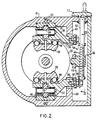
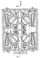
- Fig. 2 shows the support arrangement for the pivot trunnions 30 and 32 which at their control ends 56 are slidably engaged by appropriate grooves 58 formed in inwardly projecting housing wall portions 60. They are held in position by a ratio control rod or screw 62 supported in the housing 10 and provided with a threaded portion 64 carrying an adjustment member 66 to which the ends 56 of the pivot trunnions 30 and 32 are linked as shown clearly in Fig. 3.
- the pivot trunnion ends 56 have precess arms 68 mounted thereon so as to project radially in opposite directions with respect to the pivot axes of the trunnions and the axis of the control rod 62.
- the ends of the precess arms 68 are linked to the oppositely projecting ends of the adjusting member 66 by links 70.
- the transmission ratio can be controlled with this arrangement in a simple manner: Rotating the control rod 62 by way of a hand wheel 72, for example, causes the adjusting member 66 to move axially on the threaded portion 64 and, by way of links 70 provides for tilting of the pivot trunnions 30 and 32 and the traction rollers 26, 28 into a precessing position with respect to the toric discs 20, 22.
- the precessing position causes the traction rollers 26, 28 to walk to different circles of engagement with the toric discs 20, 22, to a larger circle of engagement with one and a smaller circle of engagement with the other, thereby pivoting the pivot trunnions 30 and 32 while changing the transmission ratio.
- Stop members 74 may be provided on the control shaft which determine the pivot end positions of the pivot trunnions, that is, the transmission ratio limits.
- Figs. 1 to 3 The arrangement disclosed with regard to Figs. 1 to 3 is a simple mechanical arrangement which is therefore inexpensive and reliable. However arrangements capable of transmitting substantially more power are feasible with relatively little more complicated arrangements, for example, as shown in Fig. 4.
- twin traction roller structures are utilized for higher power transmissions and in order to avoid the need for heavy and expensive axial thrust bearings for the toric discs.
- the two outer toric discs 102 and 104 are firmly mounted on the main transmission shaft 106 by way of mounting sleeves 108 and 110, the sleeve 108 being provided with a gear structure to be driven thereby.
- the inner discs 112 and 114 are mounted on a hollow transmission shaft 116 through which the main transmission shaft 106 extends and which carries an output gear 118, the hollow transmission shaft 116 being supported by bearings 120.
- the metal track members 122 for the traction roller support trunnion rollers 123 are provided with an adjustable backup structure including a wedge 124 disposed on an inclined backup plate 126 and including needle bearing structures 128 to facilitate wedging movement.
- Pistons 130 disposed in cylinders 132 abut the wedges for hydraulic operation of the wedges so as to provide the required contact forces between the traction rollers 134 and the discs 102, 104 and 112, 114. In this manner the hydraulic fluid pressure necessary for operating the pistons 130 is only relatively low which eliminates the need for high pressure fluid pumps and high pressure piston seals. Also jerky motions are not directly applied to the pistons.
- the transmission ratio control arrangement is essentially the same as the one shown in Fig. 3 for a single-unit traction roller transmission.
- the operating mechanisms for the two toric disc structures are attached to the opposite ends of an operating arm 150 to which the individual adjustment members 166 are mounted so that they are movable in unison by the operating arm and the mechanism for moving the operating arm 150.
- this mechanism consists of a threaded rod 162 but it may also be a hydraulic mechanism.
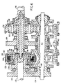
- Fig. 6 is a cross-sectional view along line VI-VI of Fig. 5 which cross-sectional view gives a full view of the transmission mechanism. The figure does not show the housing since it is not needed for an understanding.
- Fig. 6 shows the transmission input shaft 170 which at its outer end carries an input gear 172 which is in engagement with the gear structure 174 on the sleeve 108 of Fig. 5.
- the input shaft 170 is provided with a clutching structure 176 which includes a clutch bell 178 mounted on one end of an intermediate shaft 180 which extends through a hollow transmission shaft 182.
- the hollow transmission shaft 182 carries a gear 184 which is in engagement with the gear 118 mounted on the hollow traction roller transmission shaft 116 and which is driven thereby at a relative speed, variable depending on the ratio setting of pivotal traction rollers 134.
- the hollow transmission shaft 182 is provided at its end with a sun roller structure 186 which forms the center roller of a planetary type traction roller transmission of the type disclosed in applicant's US-A 48 46 008 published 11/07/89.
- the planetary type traction roller transmission includes a traction ring 188 which is mounted for rotation with the transmission output shaft 190 and has a race 192 spaced from the surface of the sun roller 186 with planetary rollers 194 being disposed in the annular space between the traction ring 188 and the sun roller 186.
- the planetary rollers 194 are supported by a carrier 196 which is firmly mounted on the other end of the intermediate shaft 180.
- the planetary roller carrier 196 is either rotated together with the input shaft 170 (forward) or it is held non-rotatable (for reverse) under the control of the clutch structure 176.
- the intermediate transmission shaft 180 is operatively connected to the clutch plate support member 206 which is mounted on the input shaft 170 so that the intermediate shaft 180 and the planetary traction roller carrier rotate with the input shaft for forward rotation of the output shaft 190. If however the clutch plates 200 and 202 are disengaged and the reverse brake band 208 engages the carrier 210 for the clutch plates 202, which carrier is connected with the clutch bell 178, the intermediate shaft 180 is locked and so is the planetary traction roller carrier 196 which then provides for reverse rotation of the ring 188 and the output shaft 190.
- Fig. 6 shows the arrangement as shown in Fig. 6 how space-efficient the arrangement actually is. It is seen that the clutch structure 176 extends into the otherwise unused toric space defined between the toric discs of one set of toric transmission discs and the planetary traction roller ring 188 extends into the toric space defined between the toric discs of the other set of toric transmission discs so that the distance between the two sets of shafts and also the transmission volume are only relatively small.
- Fig. 6 also shows the ratio control mechanism for the two toric traction roller transmission structures wherein, as also shown in Fig. 5, one operating arm 150 has its opposite ends connected to the two ratio control mechanisms for concurrent operation thereof, the operating arm 150 being movable by the rod 162.
- the rod 162 may be movable by mechanical means or it may be operable by hydraulic means such as a hydraulic cylinder and piston structure which preferably is large enough such that its operating fluid pressure requirements are essentially the same as those of the operating pistons and cylinders 130, 132 for the wedges 124.
- the support rollers 36 may be slightly curved in axial direction as shown in Fig. 2 or, although a planetary type traction roller transmission is shown, a gear type planetary traction roller transmission may be utilized.
Landscapes
- Engineering & Computer Science (AREA)
- General Engineering & Computer Science (AREA)
- Mechanical Engineering (AREA)
- Friction Gearing (AREA)
Claims (11)
- Stufenlos verstellbares Treibrollengetriebe, bestehend aus einem Gehäuse (10), zwei drehbar im Gehäuse (10) gelagerten torischen Treibscheiben (20,22), von denen eine (20) drehbar mit einer Antriebswelle (12) und die andere (22) drehbar mit einer Abtriebswelle (14) verbunden ist, und beide torische Scheiben (20,22) einander gegenüberliegen und zwischen sich eine torische Ausnehmung (24) kreisförmigen Querschnitts bilden; wobei wenigstens zwei bewegungsübertragende Treibrollen (26,28) winkelsymetrisch in der torischen Ausnehmung (24) zur Übertragung von Drehbewegung im Eingriff mit den torischen Scheiben angeordnet sind, und jede der Treibrollen (26,28) auf einem um eine zum Mittelkreis der torischen Ausnehmung (24) im wesentlichen tangentialen Stellachse schwenkbar im Gehäuse (10) angeordneten Lagerstutzen (30,32) drehbar gelagert ist, und wobei die Lagerstutzen (30,32) Lagerrollen (34,36) aufweisen, die auf einseitig um die Lagerstutzen (30,32) angeordneten teilkreisförmigen Lagerflächen (54) zur Abstützung der Lagerrollen (34,36) laufen und die Treibrollen auf den Lagerstützen (30,32) in kraftübertragenden Eingriff mit den torischen Scheiben (20,22) Zwingen, und wobei ferner jeder Lagerstutzen (30,32) ein axial herausragendes drehbar im Gehäuse (10) gelagertes Einstellende (56) besitzt,
dadurch gekennzeichnet,
daß jeder Lagerstutzen (30,32) nur eine Lagerrolle (34,36) besitzt und das Einstellende (56) jedes Lagerstutzens (30) so gelagert ist, daß es nicht nur drehbar, sondern auch in einer zur Achse der torischen Scheiben (20,22) senkrechten Ebene leicht verschiebbar ist, um dadurch den Lagerstutzen um den Abstützpunkt der Lagerrolle (34,36) auf der Lagerfläche (54) verschwenken zu können, und daß Einrichtungen zum Abstützen und kontrollierten gemeinsamen Verschwenken der Lagerstutzen (30,32) um ihre entsprechenden Abstützpunkte in bezüglich der Achse der torischen Scheiben (20,22) gleicher Drehrichtung vorgesehen sind, um dadurch eine Änderung des Getriebeübersetzungsverhältnisses einleitende Präzessionsbewegung der Treibrollen (26,28) bewirken zu können. - Treibrollengetriebe nach Anspruch 1,
dadurch gekennzeichnet,
daß das Gehäuse (10) nach innen ragende Wandvorsprünge (60) mit Lagernuten (58) besitzt, in denen die Enden (56) der Lagerstutzen gleitend gelagert sind. - Treibrollengetriebe nach Anspruch 2,
dadurch gekennzeichnet,
daß die Einrichtungen zum Verschwenken der Lagerstutzen an den Enden (56) der Lagerstutzen angebrachte Präzessionsarme (68) sind, die im wesentlichen in einer zu einer die Drehachse der Lagerstutzen und die Achse der entsprechenden Treibrollen aufnehmenden Ebene senkrechten Richtung angeordnet sind, und daß die Präzessionsarme (68) mit Vorrichtungen zum Verschwenken der Lagerstutzen (30,32) verbunden sind. - Treibrollengetriebe nach Anspruch 3,
dadurch gekennzeichnet,
daß die Lagerstutzenenden (56) in derselben Richtung herausragen und die Präzessionsarme (68) von den Lagerstutzenenden (56) parallel aber entgegengesetzt ausgerichtet abstehen und daß die mit den Präzessionsarmen verbundenen Vorrichtungen mit einem gemeinsamen Einstellglied (66) verbundene Verbindungsstäbe (70) sind, wobei das Einstellglied (66) mit einem Einstellmechanismus (62,64) zum Einstellen des Übersetzungsverhältnisses gekoppelt ist. - Treibrollengetriebe nach Anspruch 4,
dadurch gekennzeichnet,
daß das Einstellglied (66) eine mit einem Gewinde versehene Öffnung aufweist, in dem ein Gewindestab (62) aufgenommen ist, der im Gehäuse (10) drehbar gelagert ist, um dadurch das Einstellglied (66) auf dem Gewindestab hin und her bewegen zu können. - Treibrollengetriebe nach einem der
Ansprüche 1 bis 5,
dadurch gekennzeichnet,
daß die Lagerstutzenlagerrollen (34,36) in Achsrichtung gekrümmte Oberflächen aufweisen, um dadurch ein Verschwenken der Lagerstutzen zu erleichtern. - Treibrollengetriebe nach einem der
Ansprüche 1 bis 6,
dadurch gekennzeichnet,
daß die Lagerflächenanordnung (38,40) zur Abstützung jedes Lagerstutzens (30,32,134) auf einem Stützkeil (124) ruht und an jedem Stützkeil (124) ein hydraulischer Zylinder (132) mit Kolben (130) zum Einschieben des Stützkeiles (124) in den entsprechenden Raum hinter jedem Lagerstutzen (30,32,134) vorgesehen ist, um dadurch die Treibrollen auf den Lagerstutzen in festen Eingriff mit den entsprechenden torischen Scheiben (102,112;104,114) zu bringen. - Stufenlos verstellbares Treibrollengetriebe bestehend aus einem Gehäuse; drehbar im Gehäuse gelagerten koaxialen Antriebs- und Abtriebswellen (170,190); einer im Gehäuse von den Antriebs- und Abtriebswellen beabstandet, jedoch parallel dazu drehbar gelagerten Getriebehauptwelle (106), die in Drehverbindung mit der Antriebswelle steht; zwei torischen Treibrollengetriebeanordnungen (134), die auf der Getriebehauptwelle angeordnet sind und jeweils äußere und innere torische Scheiben (102,104,112,114) aufweisen, wobei die axial äußeren torischen Scheiben (102,104) in Drehverbindung mit der Getriebehauptwelle und die inneren torischen Scheiben in Drehverbindung mit einer ersten, die Hauptwelle zwischen den Treibrollengetriebeanordnungen umschließenden Getriebehohlwelle (116) stehen und jede der torischen Treibrollengetriebeanordnungen mit den torischen Scheiben im Eingriff stehende Treibrollen aufweist, die auf bezüglich einer durch die Achsen der Antriebs- und Abtriebswellen und der Hauptgetriebewelle definierten Ebene einander gegenüberliegenden Lagerstutzen gelagert sind und eine mit den Lagerstutzen verbundene Einrichtung zum Schwenken der Lagerstutzen aufweisen, um dadurch das Übersetzungsverhältnis zwischen den äußeren und den inneren torischen Scheiben ändern zu können, einer drehbar zwischen der Antriebs- und Abtriebswelle gelagerten Zwischenwelle (180), die an ihrem einen Ende eine scheibenförmige Kupplungsanordnung (176) aufweist, durch die die Zwischenwelle wahlweise mit der Antriebswelle oder einer die Zwischenwelle feststellenden Bremsanordnung (208) gekoppelt werden kann und die an ihrem anderen Ende ein Planetengetriebe (186,188,192,196) aufweist, das einen mit der Abtriebswelle drehbar verbundenen Treibring (188), einen drehbar mit der Zwischenwelle verbundenen Planetenträger (196) und ein im Eingriff mit den Planeten (194) stehendes Sonnenrad umfaßt, das auf einer zweiten, drehbar auf der Zwischenwelle gelagerten Hohlwelle (182) angeordnet ist, die über miteinander gekoppelte Treibteile (184,118) in Drehverbindung mit der ersten hohlen Getriebewelle steht, wobei die scheibenförmige Kupplungsanordnung (176) und das Planetengetriebe eine bestimmte Breite und einen bestimmten Durchmesser aufweisen und so angeordnet sind, daß Teile davon zwischen den torischen Scheiben der torischen Treibrollengetriebeanordnungen auf der Getriebehauptwelle liegen, und wobei hinter jedem Lagerstutzen eine teilkreisförmige Lagerfläche (122) angeordnet ist und jeder Lagerstutzen eine einzige, in der Lagerfläche geführte Stützrolle (123) aufweist und jeder Lagerstutzen ein axial herausragendes, drehbar im Gehäuse gelagertes Einstellende besitzt, das auch in einer zur Achse der torischen Scheibe senkrechten Richtung leicht verschiebbar ist und wobei Einrichtungen (150) zum gemeinsamen Verschwenken der Lagerstutzen vorgesehen sind, um dadurch entsprechende Präzessionsbewegungen der Treibrollen zur Einleitung einer Übersetzungsverhältnisänderung erzeugen zu können.
- Treibrollengetriebe nach Anspruch 8,
wobei das Gehäuse nach innen ragende Wandvorsprünge mit Lagernuten besitzt, in denen die Enden der Lagerstutzen gleitend gelagert sind und wobei die Einrichtungen zum Verschwenken der Lagerstutzen an den Enden der Lagerstutzen angebrachte Präzessionsarme sind, die im wesentlichen in einer, zur Drehachse der Schwenkstutzen und die Achse der entsprechenden Treibrollen aufnehmenden Ebene senkrechten Richtung angeordnet sind und die Präzessionsarme mit Vorrichtungen zum Verschwenken der Lagerstutzen verbunden sind. - Treibrollengetriebe nach Anspruch 9,
in dem die Lagerstutzenenden in derselben Richtung herausragen und die Präzessionsarme von den Lagerstutzenenden parallel aber entgegengesetzt ausgerichtet abstehen und die mit den Präzessionsarmen verbundenen Vorrichtungen mit einem gemeinsamen Einstellglied verbundene Verbindungsstäbe sind, wobei das Einstellglied mit einem Einstellmechanismus zum Einstellen des Übersetzungsverhältnisses gekoppelt ist. - Treibrollengetrieb nach Anspruch 8,
wobei die Lagerflächenanordnung (122) hinter jedem Lagerstutzen auf einem Stützkeil (124) ruht, und an jedem Stützkeil ein hydraulischer Zylinder (132) mit Kolben (130) zum Einschieben des Stützkeiles hinter jeden Lagerstutzen vorgesehen ist, um dadurch die Treibrollen auf den Lagerstutzen in festen Eingriff mit den entsprechenden torischen Scheiben zu bringen.
Applications Claiming Priority (2)
| Application Number | Priority Date | Filing Date | Title |
|---|---|---|---|
| US07/259,043 US4964312A (en) | 1988-10-17 | 1988-10-17 | Infinitely variable traction roller transmission |
| US259043 | 1988-10-17 |
Related Child Applications (1)
| Application Number | Title | Priority Date | Filing Date |
|---|---|---|---|
| EP93100533.4 Division-Into | 1993-01-15 |
Publications (2)
| Publication Number | Publication Date |
|---|---|
| EP0365872A1 EP0365872A1 (de) | 1990-05-02 |
| EP0365872B1 true EP0365872B1 (de) | 1993-08-11 |
Family
ID=22983265
Family Applications (2)
| Application Number | Title | Priority Date | Filing Date |
|---|---|---|---|
| EP19930100533 Withdrawn EP0540499A3 (en) | 1988-10-17 | 1989-10-03 | Infinitely variable traction roller transmission |
| EP89118275A Expired - Lifetime EP0365872B1 (de) | 1988-10-17 | 1989-10-03 | Stufenloses Reibrad-Getriebe |
Family Applications Before (1)
| Application Number | Title | Priority Date | Filing Date |
|---|---|---|---|
| EP19930100533 Withdrawn EP0540499A3 (en) | 1988-10-17 | 1989-10-03 | Infinitely variable traction roller transmission |
Country Status (4)
| Country | Link |
|---|---|
| US (1) | US4964312A (de) |
| EP (2) | EP0540499A3 (de) |
| DE (1) | DE68908334T2 (de) |
| ES (1) | ES2044007T3 (de) |
Cited By (1)
| Publication number | Priority date | Publication date | Assignee | Title |
|---|---|---|---|---|
| WO2008022455A1 (en) * | 2006-08-23 | 2008-02-28 | S.O.E. Technologies Inc. | Mechanical cvt drive train and control method for earth working vehicle |
Families Citing this family (50)
| Publication number | Priority date | Publication date | Assignee | Title |
|---|---|---|---|---|
| US4911030A (en) * | 1989-01-30 | 1990-03-27 | Excelermatic Inc. | Traction roller transmission ratio control arrangement |
| US4996891A (en) * | 1989-10-30 | 1991-03-05 | Excelermatic Inc. | Infinitely variable traction roller transmission |
| US4974466A (en) * | 1989-11-27 | 1990-12-04 | Excelermatic Inc. | Infinitely variable traction roller transmission |
| US5203748A (en) * | 1990-05-09 | 1993-04-20 | Canon Kabushiki Kaisha | Rotary driving system and robot operating thereon |
| US5085089A (en) * | 1991-02-06 | 1992-02-04 | Excelermatic Inc. | Infinitely variable traction roller transmission |
| US5368529A (en) * | 1992-06-29 | 1994-11-29 | Nsk Ltd. | Toroidal type continuously variable transmission |
| US5330396A (en) * | 1992-12-16 | 1994-07-19 | The Torax Company, Inc. | Loading device for continuously variable transmission |
| US5540631A (en) * | 1992-12-16 | 1996-07-30 | The Torax Company, Inc. | Continuously variable transmission with a hydraulic control system |
| JP3496350B2 (ja) | 1995-07-24 | 2004-02-09 | 日産自動車株式会社 | トロイダル型無段変速機 |
| US5916057A (en) * | 1997-05-27 | 1999-06-29 | Excelermalic Inc. | Zero spin infinitely variable traction roller transmission |
| DE10034453A1 (de) | 2000-07-15 | 2002-01-24 | Zahnradfabrik Friedrichshafen | Stufenloses Reibradgetriebe |
| JP2003049914A (ja) * | 2001-08-07 | 2003-02-21 | Nsk Ltd | トロイダル型無段変速機 |
| US7011600B2 (en) | 2003-02-28 | 2006-03-14 | Fallbrook Technologies Inc. | Continuously variable transmission |
| KR101276082B1 (ko) | 2004-10-05 | 2013-06-18 | 폴브룩 테크놀로지즈 인크 | 연속 가변 변속기 |
| KR101831828B1 (ko) | 2005-10-28 | 2018-02-23 | 폴브룩 인텔렉츄얼 프로퍼티 컴퍼니 엘엘씨 | 전동 드라이브 |
| EP1954959B1 (de) | 2005-11-22 | 2013-05-15 | Fallbrook Intellectual Property Company LLC | Stufenlos verstellbares getriebe |
| CA2976893C (en) | 2005-12-09 | 2019-03-12 | Fallbrook Intellectual Property Company Llc | Continuously variable transmission |
| EP1811202A1 (de) | 2005-12-30 | 2007-07-25 | Fallbrook Technologies, Inc. | Stufenloses Getriebe |
| US7882762B2 (en) | 2006-01-30 | 2011-02-08 | Fallbrook Technologies Inc. | System for manipulating a continuously variable transmission |
| JP4905012B2 (ja) * | 2006-06-02 | 2012-03-28 | 日本精工株式会社 | トロイダル型無段変速機 |
| US7341105B2 (en) | 2006-06-20 | 2008-03-11 | Holcim (Us) Inc. | Cementitious compositions for oil well cementing applications |
| CN102278200B (zh) | 2006-06-26 | 2014-05-14 | 福博科知识产权有限责任公司 | 无级变速器 |
| WO2008057507A1 (en) | 2006-11-08 | 2008-05-15 | Fallbrook Technologies Inc. | Clamping force generator |
| EP2125469A2 (de) | 2007-02-01 | 2009-12-02 | Fallbrook Technologies Inc. | System und verfahren zur getriebe- und/oder antriebsmotorsteuerung |
| CN104121345B (zh) | 2007-02-12 | 2017-01-11 | 福博科知识产权有限责任公司 | 无级变速器及其方法 |
| EP2700843A3 (de) | 2007-02-16 | 2017-11-08 | Fallbrook Intellectual Property Company LLC | Stufenlose Getriebe, Verfahren, Anordnungen, Baugruppen und Komponenten dafür |
| CN102943855B (zh) | 2007-04-24 | 2016-01-27 | 福博科技术公司 | 电力牵引传动装置 |
| WO2008154437A1 (en) | 2007-06-11 | 2008-12-18 | Fallbrook Technologies Inc. | Continuously variable transmission |
| CN103697120B (zh) | 2007-07-05 | 2017-04-12 | 福博科技术公司 | 无级变速器 |
| US8996263B2 (en) | 2007-11-16 | 2015-03-31 | Fallbrook Intellectual Property Company Llc | Controller for variable transmission |
| JP5783723B2 (ja) | 2007-12-21 | 2015-09-24 | フォールブルック インテレクチュアル プロパティー カンパニー エルエルシー | 自動変速機及びその方法 |
| CA2716908C (en) | 2008-02-29 | 2017-06-27 | Fallbrook Technologies Inc. | Continuously and/or infinitely variable transmissions and methods therefor |
| US8317651B2 (en) | 2008-05-07 | 2012-11-27 | Fallbrook Intellectual Property Company Llc | Assemblies and methods for clamping force generation |
| US8535199B2 (en) | 2008-06-06 | 2013-09-17 | Fallbrook Intellectual Property Company Llc | Infinitely variable transmissions, continuously variable transmissions, methods, assemblies, subassemblies, and components therefor |
| WO2009157920A1 (en) | 2008-06-23 | 2009-12-30 | Fallbrook Technologies Inc. | Continuously variable transmission |
| WO2010017242A1 (en) | 2008-08-05 | 2010-02-11 | Fallbrook Technologies Inc. | Methods for control of transmission and prime mover |
| US8469856B2 (en) | 2008-08-26 | 2013-06-25 | Fallbrook Intellectual Property Company Llc | Continuously variable transmission |
| US8167759B2 (en) | 2008-10-14 | 2012-05-01 | Fallbrook Technologies Inc. | Continuously variable transmission |
| WO2010120933A1 (en) | 2009-04-16 | 2010-10-21 | Fallbrook Technologies Inc. | Stator assembly and shifting mechanism for a continuously variable transmission |
| US8512195B2 (en) | 2010-03-03 | 2013-08-20 | Fallbrook Intellectual Property Company Llc | Infinitely variable transmissions, continuously variable transmissions, methods, assemblies, subassemblies, and components therefor |
| US8888643B2 (en) | 2010-11-10 | 2014-11-18 | Fallbrook Intellectual Property Company Llc | Continuously variable transmission |
| WO2012138610A1 (en) | 2011-04-04 | 2012-10-11 | Fallbrook Intellectual Property Company Llc | Auxiliary power unit having a continuously variable transmission |
| US9587721B2 (en) * | 2011-10-20 | 2017-03-07 | Paul Okulov | Infinitely variable traction drive employing alternate steerable rollers |
| CN107061653B (zh) | 2012-01-23 | 2020-05-26 | 福博科知识产权有限责任公司 | 无限变速式无级变速器、连续变速式无级变速器、方法、组件、子组件以及其部件 |
| KR102433297B1 (ko) | 2013-04-19 | 2022-08-16 | 폴브룩 인텔렉츄얼 프로퍼티 컴퍼니 엘엘씨 | 무단 변속기 |
| US10047861B2 (en) | 2016-01-15 | 2018-08-14 | Fallbrook Intellectual Property Company Llc | Systems and methods for controlling rollback in continuously variable transmissions |
| US10458526B2 (en) | 2016-03-18 | 2019-10-29 | Fallbrook Intellectual Property Company Llc | Continuously variable transmissions, systems and methods |
| US10023266B2 (en) | 2016-05-11 | 2018-07-17 | Fallbrook Intellectual Property Company Llc | Systems and methods for automatic configuration and automatic calibration of continuously variable transmissions and bicycles having continuously variable transmissions |
| US11215268B2 (en) | 2018-11-06 | 2022-01-04 | Fallbrook Intellectual Property Company Llc | Continuously variable transmissions, synchronous shifting, twin countershafts and methods for control of same |
| US11174922B2 (en) | 2019-02-26 | 2021-11-16 | Fallbrook Intellectual Property Company Llc | Reversible variable drives and systems and methods for control in forward and reverse directions |
Citations (1)
| Publication number | Priority date | Publication date | Assignee | Title |
|---|---|---|---|---|
| US4846008A (en) * | 1986-12-29 | 1989-07-11 | Excelermatic Inc. | Traction roller transmission |
Family Cites Families (16)
| Publication number | Priority date | Publication date | Assignee | Title |
|---|---|---|---|---|
| FR580189A (fr) * | 1923-04-19 | 1924-10-31 | Dispositif de transmission entre arbres coaxiaux | |
| GB476589A (en) * | 1935-06-15 | 1937-12-13 | Jakob Arter | Improvements in or relating to frictional change speed gears |
| US2079683A (en) * | 1936-02-27 | 1937-05-11 | Chilton Roland | Transmission |
| US2425188A (en) * | 1943-12-18 | 1947-08-05 | Honigman Hans | Motion transmitting means and adjustment thereof |
| DE817984C (de) * | 1948-10-02 | 1951-10-22 | Troester A J Fa | Stufenloses UEbersetzungsgetriebe |
| US3486391A (en) * | 1968-09-19 | 1969-12-30 | Excelermatic | Toroidal type transmission |
| US3822610A (en) * | 1972-08-31 | 1974-07-09 | R Erban | Traction roller transmission with torque loading means |
| US4086820A (en) * | 1976-06-25 | 1978-05-02 | Excelermatic, Inc. | Infinitely variable traction roller transmission |
| EP0043184B1 (de) * | 1980-05-31 | 1985-02-20 | Bl Technology Limited | Steuereinrichtungen für stufenlose Übersetzungsgetriebe |
| JPS58160664A (ja) * | 1982-03-18 | 1983-09-24 | Nippon Seiko Kk | トロイダル形無段変速機の変速装置 |
| JPS6127359A (ja) * | 1984-07-19 | 1986-02-06 | Yamaha Motor Co Ltd | 車両用トロイダル形無段変速機 |
| US4693134A (en) * | 1985-06-20 | 1987-09-15 | Excelermatic Inc. | High-powered vehicle drive train |
| US4702118A (en) * | 1986-09-22 | 1987-10-27 | Excelermatic Inc. | Hydraulically controlled infinitely variable traction roller transmission |
| US4858484A (en) * | 1987-10-26 | 1989-08-22 | Excelermatic Inc. | Infinitely variable traction roller transmission |
| US4830578A (en) * | 1987-10-26 | 1989-05-16 | Excelermatic Inc. | Hydraulic control arrangement for an infinitely variable transmission drive |
| US4885955A (en) * | 1989-03-27 | 1989-12-12 | Excelermatic Inc. | Multimode infinitely variable transmission |
-
1988
- 1988-10-17 US US07/259,043 patent/US4964312A/en not_active Expired - Lifetime
-
1989
- 1989-10-03 DE DE89118275T patent/DE68908334T2/de not_active Expired - Fee Related
- 1989-10-03 ES ES89118275T patent/ES2044007T3/es not_active Expired - Lifetime
- 1989-10-03 EP EP19930100533 patent/EP0540499A3/en not_active Withdrawn
- 1989-10-03 EP EP89118275A patent/EP0365872B1/de not_active Expired - Lifetime
Patent Citations (1)
| Publication number | Priority date | Publication date | Assignee | Title |
|---|---|---|---|---|
| US4846008A (en) * | 1986-12-29 | 1989-07-11 | Excelermatic Inc. | Traction roller transmission |
Cited By (1)
| Publication number | Priority date | Publication date | Assignee | Title |
|---|---|---|---|---|
| WO2008022455A1 (en) * | 2006-08-23 | 2008-02-28 | S.O.E. Technologies Inc. | Mechanical cvt drive train and control method for earth working vehicle |
Also Published As
| Publication number | Publication date |
|---|---|
| ES2044007T3 (es) | 1994-01-01 |
| EP0365872A1 (de) | 1990-05-02 |
| US4964312A (en) | 1990-10-23 |
| EP0540499A3 (en) | 1993-07-28 |
| DE68908334D1 (de) | 1993-09-16 |
| EP0540499A2 (de) | 1993-05-05 |
| DE68908334T2 (de) | 1994-03-24 |
Similar Documents
| Publication | Publication Date | Title |
|---|---|---|
| US5020384A (en) | Infinitely variable traction roller transmission | |
| US4964312A (en) | Infinitely variable traction roller transmission | |
| JP5133914B2 (ja) | 連続可変比動力伝達装置に関する改良 | |
| US4275610A (en) | Infinitely variable traction roller transmission | |
| US5048359A (en) | Toroidal continuously variable transmission | |
| EP1846673B1 (de) | Stufenlos verstellbares toroidgetriebe | |
| RU2382917C2 (ru) | Устройство бесступенчатого регулирования передаточного отношения (вариатор) | |
| US4484487A (en) | Hydraulically controlled infinitely variable traction roller transmission | |
| US4911030A (en) | Traction roller transmission ratio control arrangement | |
| EP0400187B1 (de) | Stufenloses Reibrollengetriebe | |
| US4630494A (en) | Radially oriented nutational traction drive transmission | |
| JPH07113398B2 (ja) | 牽引ロ−ラ無段変速機 | |
| EP0425914B1 (de) | Stufenloses Reibrollengetriebe | |
| US4745821A (en) | Speed ratio adjusting system for nutational traction drive transmissions | |
| JP2002013605A (ja) | トロイダル型無段変速機 | |
| CA1149642A (en) | Torque transmitting body for traction drive transmissions and normal friction force developing method | |
| JP3480034B2 (ja) | トロイダル型無段変速機 | |
| US4454782A (en) | Torque transmitting body for traction drive transmissions and normal friction force developing method | |
| JPH0814350A (ja) | トロイダル型無段変速機 | |
| EP0210231B1 (de) | Radial ausgerichtetes nutationsfriktionsgetriebe | |
| CA1066091A (en) | Variable speed transmission device | |
| JPH0560198A (ja) | 牽引ローラー無段変速機 | |
| JP2601058Y2 (ja) | トロイダル型無段変速機 | |
| JPH09269040A (ja) | トロイダル型無段変速機 | |
| JP2000205361A (ja) | トロイダル型無段変速機の組立方法 |
Legal Events
| Date | Code | Title | Description |
|---|---|---|---|
| PUAI | Public reference made under article 153(3) epc to a published international application that has entered the european phase |
Free format text: ORIGINAL CODE: 0009012 |
|
| AK | Designated contracting states |
Kind code of ref document: A1 Designated state(s): DE ES FR GB IT SE |
|
| 17P | Request for examination filed |
Effective date: 19901016 |
|
| 17Q | First examination report despatched |
Effective date: 19920422 |
|
| ITF | It: translation for a ep patent filed | ||
| GRAA | (expected) grant |
Free format text: ORIGINAL CODE: 0009210 |
|
| AK | Designated contracting states |
Kind code of ref document: B1 Designated state(s): DE ES FR GB IT SE |
|
| XX | Miscellaneous (additional remarks) |
Free format text: TEILANMELDUNG 93100533.4 EINGEREICHT AM 03/10/89. |
|
| ET | Fr: translation filed | ||
| REF | Corresponds to: |
Ref document number: 68908334 Country of ref document: DE Date of ref document: 19930916 |
|
| REG | Reference to a national code |
Ref country code: ES Ref legal event code: FG2A Ref document number: 2044007 Country of ref document: ES Kind code of ref document: T3 |
|
| PLBE | No opposition filed within time limit |
Free format text: ORIGINAL CODE: 0009261 |
|
| STAA | Information on the status of an ep patent application or granted ep patent |
Free format text: STATUS: NO OPPOSITION FILED WITHIN TIME LIMIT |
|
| 26N | No opposition filed | ||
| EAL | Se: european patent in force in sweden |
Ref document number: 89118275.0 |
|
| PGFP | Annual fee paid to national office [announced via postgrant information from national office to epo] |
Ref country code: ES Payment date: 19961002 Year of fee payment: 8 |
|
| PGFP | Annual fee paid to national office [announced via postgrant information from national office to epo] |
Ref country code: FR Payment date: 19970826 Year of fee payment: 9 |
|
| PGFP | Annual fee paid to national office [announced via postgrant information from national office to epo] |
Ref country code: GB Payment date: 19971003 Year of fee payment: 9 |
|
| PG25 | Lapsed in a contracting state [announced via postgrant information from national office to epo] |
Ref country code: ES Free format text: LAPSE BECAUSE OF NON-PAYMENT OF DUE FEES Effective date: 19971004 |
|
| PGFP | Annual fee paid to national office [announced via postgrant information from national office to epo] |
Ref country code: SE Payment date: 19971027 Year of fee payment: 9 |
|
| PG25 | Lapsed in a contracting state [announced via postgrant information from national office to epo] |
Ref country code: GB Free format text: LAPSE BECAUSE OF NON-PAYMENT OF DUE FEES Effective date: 19981003 |
|
| PG25 | Lapsed in a contracting state [announced via postgrant information from national office to epo] |
Ref country code: SE Free format text: LAPSE BECAUSE OF NON-PAYMENT OF DUE FEES Effective date: 19981004 |
|
| GBPC | Gb: european patent ceased through non-payment of renewal fee |
Effective date: 19981003 |
|
| EUG | Se: european patent has lapsed |
Ref document number: 89118275.0 |
|
| PG25 | Lapsed in a contracting state [announced via postgrant information from national office to epo] |
Ref country code: FR Free format text: LAPSE BECAUSE OF NON-PAYMENT OF DUE FEES Effective date: 19990630 |
|
| REG | Reference to a national code |
Ref country code: FR Ref legal event code: ST |
|
| REG | Reference to a national code |
Ref country code: ES Ref legal event code: FD2A Effective date: 19981113 |
|
| PG25 | Lapsed in a contracting state [announced via postgrant information from national office to epo] |
Ref country code: IT Free format text: LAPSE BECAUSE OF NON-PAYMENT OF DUE FEES Effective date: 20051003 |
|
| PGFP | Annual fee paid to national office [announced via postgrant information from national office to epo] |
Ref country code: DE Payment date: 20071031 Year of fee payment: 19 |
|
| PG25 | Lapsed in a contracting state [announced via postgrant information from national office to epo] |
Ref country code: DE Free format text: LAPSE BECAUSE OF NON-PAYMENT OF DUE FEES Effective date: 20090501 |