EP0261559A1 - Abri de sécurité et sa méthode de construction - Google Patents
Abri de sécurité et sa méthode de construction Download PDFInfo
- Publication number
- EP0261559A1 EP0261559A1 EP87113476A EP87113476A EP0261559A1 EP 0261559 A1 EP0261559 A1 EP 0261559A1 EP 87113476 A EP87113476 A EP 87113476A EP 87113476 A EP87113476 A EP 87113476A EP 0261559 A1 EP0261559 A1 EP 0261559A1
- Authority
- EP
- European Patent Office
- Prior art keywords
- shelter
- shell
- shell means
- metallic
- unitary
- Prior art date
- Legal status (The legal status is an assumption and is not a legal conclusion. Google has not performed a legal analysis and makes no representation as to the accuracy of the status listed.)
- Granted
Links
Images


Classifications
-
- E—FIXED CONSTRUCTIONS
- E04—BUILDING
- E04H—BUILDINGS OR LIKE STRUCTURES FOR PARTICULAR PURPOSES; SWIMMING OR SPLASH BATHS OR POOLS; MASTS; FENCING; TENTS OR CANOPIES, IN GENERAL
- E04H9/00—Buildings, groups of buildings or shelters adapted to withstand or provide protection against abnormal external influences, e.g. war-like action, earthquake or extreme climate
- E04H9/04—Buildings, groups of buildings or shelters adapted to withstand or provide protection against abnormal external influences, e.g. war-like action, earthquake or extreme climate against air-raid or other war-like actions
- E04H9/10—Independent shelters; Arrangement of independent splinter-proof walls
-
- E—FIXED CONSTRUCTIONS
- E04—BUILDING
- E04B—GENERAL BUILDING CONSTRUCTIONS; WALLS, e.g. PARTITIONS; ROOFS; FLOORS; CEILINGS; INSULATION OR OTHER PROTECTION OF BUILDINGS
- E04B1/00—Constructions in general; Structures which are not restricted either to walls, e.g. partitions, or floors or ceilings or roofs
- E04B1/348—Structures composed of units comprising at least considerable parts of two sides of a room, e.g. box-like or cell-like units closed or in skeleton form
- E04B1/34815—Elements not integrated in a skeleton
- E04B1/3483—Elements not integrated in a skeleton the supporting structure consisting of metal
Definitions
- the present invention generally relates to shelters and shelter construction methods and more particularly is concerned with a shelter in which the entire body of the shelter may be formed from two complementarily positioned shells and which will shieldingly attenuate the passage of electromagnetic waves into the shelter.
- the present invention provides a shelter and method of constructing the shelter comprised of a unitary first shell means, a unitary second shell means, sealing means, and entryway means.
- the unitary first shell means forms a unitary top wall, bottom wall, and first end wall.
- the unitary second shell means forms a unitary second end wall, first side wall, and second side wall.
- the first shell means and second shell means are complementarily positioned to create the shelter.
- the sealing means sealingly engages the first and second shell means and may comprise a first metallic member bonded along the peripheral edge of the first shell means and a second metallic member bonded along the peripheral edge of the second shell means.
- the first and second metallic members facilitate the welding connection of the first shell means to the second shell means without delaminating the bonding in, or deforming, the first or second shell means and shieldingly attenuate the passage of electromagnetic waves into the shelter.
- the entryway means is located in at least one of the wall for sealably allowing entry into and exit from the shelter and may include means for shieldingly attenuating the passage of electromagnetic waves into the shelter,
- the shelter and method may also include wheel well means for allowing the shelter to be transportably attached to a transport vehicle.
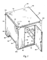
- FIGURE 1 present one embodiment of the shelter, generally desginated 20, of the present invention.
- the shelter 20 is basically comprised of a unitary first shell means 22, a unitary second shell means 24, sealing means 26, and entryway means 28, best seen in FIGURE 2.
- the unitary first shell means 22 is used for forming a unitary top wall 30, bottom wall 32, and first end wall 34.
- the unitary second shell means 24 is used for forming a unitary second end wall 36, first side wall 38, and second side wall 40.
- the first and second shell means 22, 24 are complementarily positioned to create the shelter 20, as seen in FIGURE 2.
- the sealing means 26 is used for sealingly engaging the first and second shell means 22, 24, and may also comprise means for shieldingly attenuating the passage of electromagentic waves into the shelter 20.
- the entryway means 28 is located in at least one of the walls, 30, 32, 34, 36, 38, 40 and is used for sealably allowing entry into and exit from the shelter 20.
- the entryway means 28 may also include means for shieldingly attenuating the passage of electromagnetic waves into the shelter 20.
- the first shell means 22 may be formed from a single, formable, generally rectangular, and planar panel, also designated 22.
- the panel 22 should have at least two bends 42, 44.
- the bends 42, 44 should give the panel 22 the shape necessary to provide the top, bottom, and first end walls 30, 32, 34 of the first shell means.
- the second shell means 24 may be formed from a single, formable, generally retangular, and planar panel 24.
- the panel 24 should have at least two bends 46, 48.
- the bends 46, 48 should give the panel 24 the shape necessary to provide the second end, first side, and second side walls 36, 38, 40 of the second shell means 24.
- the bends 42, 44, 46, 48 in the prototype are made transversely in the panels 22, 24, although other bending arrangements are possible, such as making longitudinal bends in one panel and transverse bends in the other.
- the first and second shell means or panels 22, 24 may each individually comprise a core 50 of filler material and at least two planar face plates 52, 54, with the core being bonded between the face plates 52, 54.
- the first and second shell means or panels 22, 24 will each individually comprise at least two metallic planar face plates also designated 52, 54 and a non-metallic honeycomb core 50 with the core 50 being adhesively bonded between the face plates 52, 54.
- the sealing means 26 comprises welding means, also designated 26, attached along the peripheral edge of each of the first and second means 22, 24, i.e., there should be a welding means 26 attached along the peripheral edge 56 of the first shell means 22 and a welding means 26 bonded along the peripheral edge 58 of the second shell means 24.
- the welding means 26 is used for facilitating the welding connection of the first shell means 22 to the second shell means 24 and for displacing the heat associated with making the weld away from the first and second shell means 22, 24.
- weld 60 to be made without deforming the first shell means 22, the second shell means 24, or the welding means 26; without delaminating the bonding within the first and second shell means 22, 24; and without delaminating the bonding between the welding means 26 and the first and second shell means 22, 24.
- the present invention also includes the method of constructing the shelter 20 described supra.
- the method basically comprises the steps of: ...making at least two bends 42, 44 in a unitary and formable first shell means 22 in order to form a unitary top wall 30, bottom wall 32, and first end wall 34; ...making at least two bends 46, 48 in a unitary and formable second shell means 24 in order to form a unitary second end wall 36, first side wall 38, and second side wall 40; ...complementarily positioning the first and second shell means 22, 24 to create the shelter 20; ...sealingly engaging the first and second shell means 22, 24; and ...sealably allowing entry into and exit from the shelter 20 through at least on the the walls 30, 32, 34, 36, 38, 40.
- the first and second shell means 22, 24 may each comprise at least two planar face plates 52, 54 and a core 50 of filler material, the core being bonded between the face plates 52, 54.
- the first and second shell means 22, 24 should each comprise at least two metallic planar face plates 52, 54 and a non-metallic honeycomb core 50, the core being adhesively bonded between the face plates.
- the sealing step of the method may further comprise the steps of: ...bonding a welding means 26 to the peripheral edge 56, 58 of each of the first and second shell means 22, 24; and ...welding the welding means 26 of the first shell means 22 to the welding means 26 of the second shell means 24 without deforming the first shell means 22, the sec ond shell means 24, or the welding means 26; without delaminating the bonding between the welding means 26 and the first and second shell means 22, 24; and without delaminating the adhesive bonding within the first and second shell means 22, 24.
- the method may further comprise the step of shieldingly attenuating the passage of electromagnetic waves into the shelter 20.
- This shielding step is normally effected by the type of sealing implemented in the steps of sealing engaging the first and second shell means 22, 24 and in the sealable entry step. The details of implementing these steps are discussed, infra, as is the construction of the first and second shell means 22, 24 which is necessary to complete the shielding.
- the welding means 26 may comprise a first metallic member 62 and a second metallic member 64.
- first member 62 has a bottom end 66 bonded along the peripheral edge 56 of the first shell means 22 and has a top end 68.
- the second member 64 has a bottom end 70 bonded along the peripheral edge 58 of the second shell means 24 and has a top end 72.
- the top end 68 of the first member 62 should weld receivingly adjoin the top end 72 of the second member 64 when the first and second shell means 22, 24 ar complementarily positioned to form the shelter 20.
- the first and second members 62, 64 are extruded, hollow, metallic members, preferably made from aluminum, aluminum alloy, or equivalent.
- the transversely cross-sectional bottom end 66 of the first member 62 is generally retangular shaped and is adhesively bonded along the peripheral edge 56 of the first shell means 22.
- the transversely cross-sectional bottom end 70 of the second member 64 is generally rectangularly shaped and is adhesively bonded along the peripheral edge 58 of the second shell means 24.
- the transversely cross-sectional top end 68 of the first member 62 is generally triangularly shaped and has a triangular side 74 generally facing the inside of the shelter 20 and a triangular side 76 generally facing the outside of the shelter 20.
- the apex 78 of the triangular top end 68 is slightly flattened to receive the weld 60.
- the transversely cross-sectional top end 72 of the second member 64 is generally triangularly shaped and has a triangular side 80 generally facing the inside of the shelter and a triangular side 82 generally facing the outside of the shelter 20.
- the apex 84 of the triangular top end 72 is slightly flattened to receive the weld 60.
- the inside facing triangular side 74 of the first member 62 should complementarily adjoin the inside facing triangular side 80 of the second member 64, i.e., the adjoined inside facing triangular sides 74, 80 should allow the walls of the first and second shell means 22, 24 to which the adjoined inside facing triangular side 74, 80 are bonded to be disposed in perpendicular relationship.
- the adjoined inside triangular sides 74, 80 should facilitate an angular relationship of ninety degrees between adjoining walls.
- the outside facing triangular sides 76, 82 of the first and second members 62, 64 should form a surface generally perpendicular to the plane of the adjoining inside facing triangular sides 74, 80 and the flattened apexes 78, 84 of the top ends 68, 72 should adjoin to form a weld receiving crevice, as exemplified in FIGURES 3 and 4.
- first and second metallic members 62, 64 may be of any shape which will allow the first and second shell means 22, 24 to be welded together and that the adjacent walls of the shelter may have angular relationships other than ninety degrees.
- first and second shell 22, 24 means may be fastened together by other methods than welding, with or without utilizing the welding means 26, such as adhesive bonding, mechanical fastening, etc., although welding is the most efficient method known to the inventor which also shieldingly attenuates the passage of electromagnetic waves through the fastening method into the shelter 20.
- the prototype shelter 20 and method also comprises cap means 86, attached to the outside surface of the adjoined first and second metallic members 62, 64 for covering the first and second metallic members 62, 64.
- the cap means 86 may conform to the shape of the outside surface of the adjoined first and second metallic members 62, 64.
- the cap means 86 of the prototype are mechanically fastened with rivets to the first and second metallic members 62, 64 although other forms of fastening, such as adhesive bonding, welding, bolts, screws, etc. may be used.
- the cap means 86 are extruded from the same material as the first and second metallic members 62, 64.
- the cap means 86 also add structural integrity to the shelter 20.
- the outside surface of the bottom end 66, 70 of each of the first and second metallic members 62, 64 has a recess 88, 90 for receiving the cap means 86.
- the recesses 88, 90 should be of sufficient depth to maintain the outside surface of the cap means 86 generally flush with the outside face plates 52 of the first and second shell means 22, 24.
- the prototype shelter 20 and method, illustrated in FIGURE 2 comprises wheel well means 92, 94, located near the opposite first and second side walls 38, 40 of the shelter 20, for receiving the wheels of a transport vehicle and for allowing the shelter 20 to be transportably attached to a transport vehicle.
- the wheel well means 92, 94 may comprise means for shieldingly attenuating the passage of electromagnetic waves into the shelter 20.
- the prototype of the shelter and method 20 was designed to meet the current requirements of military MIL-S-5541 specification for shelter model no. S-250 and was designed for use on a truck, such as a pickup. More specifically, the prototype shelter 20 was designed to be mounted on the U.S. Army's latest 11/4 ton, four wheel drive vehicle.
- the entryway means 28 of the military prototype is located in the second end wall 36 of the second shell means 24, as the second end wall 24 allows the easiest access from outside a typical pickup.
- the entryway means 28 may be located in any wall 30, 32, 34, 36, 38, 40 of the shelter 20 to satisfy a particular need or desire.
- the entryway means 28 of the military prototype includes a door 28 which is inset into the second end wall 36 when the door is closed.
- the door jamb 96 extends around all four sides of the doorway to provide a good seal and to attenuate the passage of electromagnetic waves into the shelter 20.
- the planar face plates 52, 54 are made of .040 inch thick aluminum sheets and the core 50 is a non-metallic phenolic coated paper honeycomb, best seen in FIGURES 3 and 4.
- the face plates 52, 54 of the prototype extend beyond the core 50 along the peripheral edges 56, 58 of the first and second shell means 22, 24 to create a channel in which the bottom ends 66, 70 of the first and second metallic members 62, 64 are adhesively and integrally bonded, as best seen in FIGURES 3 and 4.
- the first and second metallic members are an integral part of the first and second shell means 22, 24.
- Thermal barriers 98, 99, 100, 101 are provided in the channel to provide a thermal break and also are utilized as electrical continuity barriers in order to provide two separate electrical ground planes utilizing face plates 52 and 54.
- the thermal barriers 98, 99, 100, 101 are made of plastic laminate.
- transverse bends 42, 44, 46, 48 are made by crimping the planar panels 22, 24 on the side which is to be the inside of the shelter 20.
- the sealing means 26 or first ans second metallic members 62, 64 extend completely around the peripheral edges 56, 58 except at the transverse bends 42, 44, 46, and 48 because of the size reductions and structural distortions creayed by the crimping and bending.
- the phenolic coated paper honeycomb core 50 is fiber reinforced in the area of the transverse bends 42, 44, 46, 48 in the prototype. The fiber reinforcement gives the honeycomb core 50 the resilience necessary to prevent shattering of the core in the transverse bends 42, 44, 46, 48.
- the corners of the shelter created by the transverse bends 42, 44, 46, 48 are sealed with upper corner caps 102 and lower corner caps 104. Although not all of the corner caps 102, 104 are visible in the drawings, there are a total of eight corner caps on the prototype shelter 20, one corner cap on each corner.
- the upper corner caps 102 may include lifting eyes, as exemplified in FIGURE 1, to allow mechanically lifting the shelter 20 on and off a truck and a means of securing the shelter to the vehicle.
- the corner caps 102, 104 protect and strengthen the corners of the shelter 20 and provide shielding at the corners to attenuate the passage of electromagnetic waves into the shelter 20.
- the corner caps 102, 104 may be mechanically fastened with rivets, bolts, screws, etc. to the shelter 20; and in the prototype they are riveted to the shelter.
- the prototype corner caps 102, 104 are made of aluminum alloys.
- planar panels 22, 24 from which the prototype first and second shelter means 22, 24 are made are of aluminum sheet and phenolic coated paper honeycomb construction, which provides electromagnetic wave shielding.
- the welding means 26 or first and second metallic members 62, 64 of the prototype shelter 20, are designed to allow the first and second shelter means 22, 24 to be welded together in order to provide good electromagnetic wave attenuation along the adjoining edges of the first and second shelter means 22, 24.
- peripheral edges 106, 108 of the wheel well means 92, 94 are of similar construction to the peripheral edges 56, 58 of the first and second shell means 22, 24 discussed supra.
- Metallic members substantially identical to the first and second members 62, 64 are integrally bonded to the contacting peripheral edges 106 of wheel well means 92, 94 and the first shell means 22. This engagement between the wheel well means 92, 94 and the first shell means 22 is then welded and covered with cap means 110, substantially identically to the engagement of the first and second shell means 22, 24.
- metallic members which are rectangular in transverse cross-section are integrally bonded to the contacting peripheral edges 108 of the wheel well means 92, 94 and the second shell means 24.
- These rectangular metallic members fit together to form a ninety-degree corner and are covered with an extruded cap means 111 which is extruded in a shape to fit the ninety-degree corner.
- the rectangular metallic members are not welded together, but the ninety-degree cap means 111 is mechanically fastened to the rectangular metallic members and this mechanical fastening engages the wheel well means 92, 94 to the second shell means 24 in the prototype.
- the cap means 110, 111 are mechanically fastened to the metallic members with rivets, although bolts, screws and other types of fastening will work.
Landscapes
- Engineering & Computer Science (AREA)
- Architecture (AREA)
- Civil Engineering (AREA)
- Structural Engineering (AREA)
- Business, Economics & Management (AREA)
- Emergency Management (AREA)
- Environmental & Geological Engineering (AREA)
- Physics & Mathematics (AREA)
- Electromagnetism (AREA)
- Buildings Adapted To Withstand Abnormal External Influences (AREA)
Applications Claiming Priority (2)
| Application Number | Priority Date | Filing Date | Title |
|---|---|---|---|
| US907460 | 1978-05-19 | ||
| US06/907,460 US4787181A (en) | 1986-09-15 | 1986-09-15 | Shelter and shelter construction method |
Publications (2)
| Publication Number | Publication Date |
|---|---|
| EP0261559A1 true EP0261559A1 (fr) | 1988-03-30 |
| EP0261559B1 EP0261559B1 (fr) | 1990-05-23 |
Family
ID=25424128
Family Applications (1)
| Application Number | Title | Priority Date | Filing Date |
|---|---|---|---|
| EP87113476A Expired EP0261559B1 (fr) | 1986-09-15 | 1987-09-15 | Abri de sécurité et sa méthode de construction |
Country Status (4)
| Country | Link |
|---|---|
| US (1) | US4787181A (fr) |
| EP (1) | EP0261559B1 (fr) |
| CA (1) | CA1290912C (fr) |
| DE (1) | DE3762898D1 (fr) |
Cited By (1)
| Publication number | Priority date | Publication date | Assignee | Title |
|---|---|---|---|---|
| AT402417B (de) * | 1994-03-08 | 1997-05-26 | Krines Manfred | Wärmeisoliertes gebäude |
Families Citing this family (33)
| Publication number | Priority date | Publication date | Assignee | Title |
|---|---|---|---|---|
| USD366645S (en) | 1990-10-15 | 1996-01-30 | Dirck Ronald L | Prisoner transport module |
| US5325649A (en) * | 1992-07-07 | 1994-07-05 | Nikken Seattle, Inc. | Easily-assembled housing structure and connectors thereof |
| US5813174A (en) * | 1996-03-28 | 1998-09-29 | Waller; James E. | Closet vault |
| AU737395B2 (en) * | 1999-08-26 | 2001-08-16 | Honda Giken Kogyo Kabushiki Kaisha | A joint structure for extruded members |
| US6539674B2 (en) | 1999-09-13 | 2003-04-01 | Floyd Arnold | Work bench-tornado safe room |
| US6334278B1 (en) * | 1999-09-13 | 2002-01-01 | Steelco Incorprorated | Tornado safe room |
| DE202005001260U1 (de) * | 2005-01-26 | 2006-06-01 | WEW Westerwälder Eisenwerk GmbH | Containeranordnung |
| US7237362B2 (en) * | 2005-04-18 | 2007-07-03 | Bishop Richard B | Safe room |
| DE102006045991A1 (de) * | 2006-09-27 | 2008-04-10 | Rheinmetall Landsysteme Gmbh | Geschützte Infanteriekabine bevorzugt für den Häuserkampf insbesondere in urbanen Gebieten |
| US7690159B1 (en) | 2007-03-16 | 2010-04-06 | Floyd Arnold | Relocatable personal and/or pet safety appliance |
| US7600319B2 (en) * | 2007-06-28 | 2009-10-13 | Aar Corp. | Method of making an electromagnetic interference shielded panel |
| USD591007S1 (en) * | 2007-12-25 | 2009-04-21 | O'neill Edward J | Panel member for a feeder assembly |
| US8642900B2 (en) | 2009-10-16 | 2014-02-04 | Emprimus, Llc | Modular electromagnetically shielded enclosure |
| US8547710B2 (en) | 2009-10-16 | 2013-10-01 | Emprimus, Llc | Electromagnetically shielded power module |
| US8760859B2 (en) | 2010-05-03 | 2014-06-24 | Emprimus, Llc | Electromagnetically-shielded portable storage device |
| US8599576B2 (en) | 2010-10-29 | 2013-12-03 | Emprimus, Llc | Electromagnetically-protected electronic equipment |
| US8643772B2 (en) | 2010-11-05 | 2014-02-04 | Emprimus, Llc | Electromagnetically shielded video camera and shielded enclosure for image capture devices |
| WO2012061746A2 (fr) | 2010-11-05 | 2012-05-10 | Emprimus, Inc. | Caméra à blindage électromagnétique et enceinte blindée pour dispositifs de saisie d'images |
| US9093755B2 (en) | 2010-12-20 | 2015-07-28 | Emprimus, Llc | Lower power localized distributed radio frequency transmitter |
| US9420219B2 (en) | 2010-12-20 | 2016-08-16 | Emprimus, Llc | Integrated security video and electromagnetic pulse detector |
| US8933393B2 (en) | 2011-04-06 | 2015-01-13 | Emprimus, Llc | Electromagnetically-shielded optical system having a waveguide beyond cutoff extending through a shielding surface of an electromagnetically shielding enclosure |
| US8505253B1 (en) | 2012-10-20 | 2013-08-13 | Holland Medford | Shelter that is capable of withstanding strong winds |
| WO2014151978A2 (fr) | 2013-03-14 | 2014-09-25 | Emprimus, Llc | Enceinte électronique protégée électromagnétiquement |
| CN103510725B (zh) * | 2013-10-22 | 2014-08-20 | 广州鸿力复合材料有限公司 | 一种整体卫浴间 |
| USD742030S1 (en) * | 2014-09-08 | 2015-10-27 | Armored Closet Llc | Safety shelter |
| USD844177S1 (en) * | 2016-10-06 | 2019-03-26 | Strategic Solutions Unlimited, Inc. | Modular composite shelter system panel |
| US10240337B2 (en) * | 2016-12-06 | 2019-03-26 | Stephen T. Evert | Personal, relocatable protective enclosure |
| US11274464B2 (en) * | 2018-09-13 | 2022-03-15 | Baker Engineering & Risk Consultants, Inc. | Fragment-, overpressure-, radiation-, and toxic-resistant emergency safety shelter |
| EE05856B1 (et) * | 2019-01-18 | 2023-06-15 | Silen Oü | Ventilatsioonisüsteemiga mobiilne kabiin ja meetod selle ventileerimiseks |
| CN109606571A (zh) * | 2019-02-11 | 2019-04-12 | 企力(大连)海事科技有限公司 | 具有焊接铝蜂窝全封闭凹形托盘的船用冷库本体 |
| US12071785B1 (en) | 2020-06-29 | 2024-08-27 | Steve Galindo | Above ground tornado shelter |
| US11242693B1 (en) * | 2020-06-29 | 2022-02-08 | Steve Galindo | Above ground tornado shelter |
| US12258780B1 (en) | 2021-12-03 | 2025-03-25 | Vincent D. Mims | Removeable above-ground storm shelter and method of use |
Citations (4)
| Publication number | Priority date | Publication date | Assignee | Title |
|---|---|---|---|---|
| US3991242A (en) * | 1973-10-30 | 1976-11-09 | Brunswick Corporation | Panel end structure |
| US4144692A (en) * | 1977-05-03 | 1979-03-20 | Jonas Gerald L | Building unit |
| DE2951668A1 (de) * | 1979-12-21 | 1981-07-02 | Knauss, Heydwolff, 8881 Bächingen | Begehbarer prismatischer container |
| FR2553130A1 (fr) * | 1983-10-10 | 1985-04-12 | Huh Phil Yool | Cellule de chambre |
Family Cites Families (23)
| Publication number | Priority date | Publication date | Assignee | Title |
|---|---|---|---|---|
| CA741049A (en) * | 1966-08-23 | J. Palfey Albert | Self sustaining enclosure | |
| GB190509560A (en) * | 1905-05-06 | 1905-12-21 | William Thom Jack | Improvements in and relating to Tanks, Cisterns, and the like. |
| US1062077A (en) * | 1911-01-25 | 1913-05-20 | William H Burk | Hollow tile. |
| US2894290A (en) * | 1957-02-06 | 1959-07-14 | Lundstedt Margit Elisabeth | Collapsible cabin |
| DE1252578B (de) * | 1964-03-30 | 1967-10-19 | Midland Ross Corporation, Cleve land, Ohio (V St A) | Behalter wie Gehäuse mit mehrschichtiger Wandung |
| NL147817B (nl) * | 1965-03-11 | 1975-11-17 | Lely Nv C Van Der | Werkwijze voor het voorfabriceren van een element voor een gebouw. |
| US3382625A (en) * | 1965-05-19 | 1968-05-14 | Robert S. Kuss | Prestressed enclosure |
| US3463526A (en) * | 1967-09-25 | 1969-08-26 | United Aircraft Corp | Weldable attachments for bonded sandwich panel structures |
| US3496689A (en) * | 1968-01-08 | 1970-02-24 | Winnebago Ind Inc | Sandwich panel structure |
| US3517468A (en) * | 1968-07-22 | 1970-06-30 | John Thomas Woods | Audiometric enclosure |
| US3909995A (en) * | 1970-03-02 | 1975-10-07 | Winnebago Ind Inc | Pick-up cover |
| US3629982A (en) * | 1970-07-15 | 1971-12-28 | Us Air Force | Portable foldable shelter |
| NL7017203A (fr) * | 1970-11-25 | 1972-05-29 | ||
| US3880458A (en) * | 1974-03-29 | 1975-04-29 | Gene F Jackson | Camper module |
| US3968989A (en) * | 1974-07-18 | 1976-07-13 | Ronald Schippers | Enclosure structure |
| DE2607855A1 (de) * | 1976-02-26 | 1977-09-01 | Hofmann Igl Ernest | Verschliessbarer muelltonnenkasten |
| US4115656A (en) * | 1976-04-08 | 1978-09-19 | Sanders Associates, Inc. | Shielded passageway interconnection for electromagnetic interference shielded shelters |
| US4192113A (en) * | 1977-06-27 | 1980-03-11 | Armco Inc. | Corner assembly for wall panels |
| US4189885A (en) * | 1978-08-29 | 1980-02-26 | Wolverine Aluminum Corporation | Channel member for siding construction |
| AT376409B (de) * | 1979-06-28 | 1984-11-26 | Hutter & Schranz Bautech | Gehaeuse, insbesondere fahrzeugaufbau |
| US4271975A (en) * | 1979-08-23 | 1981-06-09 | The Boeing Company | Lightweight cargo container and fittings |
| DE3023972A1 (de) * | 1980-06-26 | 1982-01-21 | Dyna-Plastik-Werke Gmbh, 5060 Bergisch Gladbach | Bausatz fuer einen behaelter, insbesondere als nothaus |
| EP0057909B1 (fr) * | 1981-02-06 | 1985-01-16 | Rainer Bischoff | Construction d'une caravane |
-
1986
- 1986-09-15 US US06/907,460 patent/US4787181A/en not_active Expired - Lifetime
-
1987
- 1987-09-10 CA CA000546567A patent/CA1290912C/fr not_active Expired
- 1987-09-15 DE DE8787113476T patent/DE3762898D1/de not_active Expired - Lifetime
- 1987-09-15 EP EP87113476A patent/EP0261559B1/fr not_active Expired
Patent Citations (4)
| Publication number | Priority date | Publication date | Assignee | Title |
|---|---|---|---|---|
| US3991242A (en) * | 1973-10-30 | 1976-11-09 | Brunswick Corporation | Panel end structure |
| US4144692A (en) * | 1977-05-03 | 1979-03-20 | Jonas Gerald L | Building unit |
| DE2951668A1 (de) * | 1979-12-21 | 1981-07-02 | Knauss, Heydwolff, 8881 Bächingen | Begehbarer prismatischer container |
| FR2553130A1 (fr) * | 1983-10-10 | 1985-04-12 | Huh Phil Yool | Cellule de chambre |
Cited By (1)
| Publication number | Priority date | Publication date | Assignee | Title |
|---|---|---|---|---|
| AT402417B (de) * | 1994-03-08 | 1997-05-26 | Krines Manfred | Wärmeisoliertes gebäude |
Also Published As
| Publication number | Publication date |
|---|---|
| CA1290912C (fr) | 1991-10-22 |
| DE3762898D1 (de) | 1990-06-28 |
| EP0261559B1 (fr) | 1990-05-23 |
| US4787181A (en) | 1988-11-29 |
Similar Documents
| Publication | Publication Date | Title |
|---|---|---|
| EP0261559B1 (fr) | Abri de sécurité et sa méthode de construction | |
| US4940279A (en) | Cargo vehicle wall construction | |
| US7588286B2 (en) | Logistics panel for use in a sidewall of a trailer | |
| US5260525A (en) | Panel assemblies | |
| US10125539B2 (en) | Door with impact resistant light | |
| US7642470B2 (en) | Electromagnetic interference shielded panel | |
| US4711057A (en) | Subassembly for geodesically reinforced honeycomb structures | |
| GB2115033A (en) | Framework block or brick | |
| JP3243705B2 (ja) | 接着構造による荷箱 | |
| SE506587C2 (sv) | Huskonstruktion samt byggelement och förfarande för uppbyggnad av en dylik huskonstruktion | |
| CN214607253U (zh) | 方舱舱板及方舱 | |
| CN213477161U (zh) | 一种多层装配式建筑 | |
| JPH0210233Y2 (fr) | ||
| EP0266869A1 (fr) | Container construit pour fournir un blindage contre toute radiation électromagnétique | |
| JPS6336102Y2 (fr) | ||
| JP2716766B2 (ja) | 外装材一体形軽量気泡コンクリートパネルの構造躯体への施工方法 | |
| JP3117540B2 (ja) | 窓の取付方法 | |
| JPH0516831Y2 (fr) | ||
| JP2891643B2 (ja) | ガラスブロックの組積構造 | |
| JPH0629163Y2 (ja) | トラックの荷台ボデーの側壁構造 | |
| JP2002250012A (ja) | 防音パネル及びその接合方法 | |
| JP2006161405A (ja) | 間仕切壁の耐火構造 | |
| JPH0110391Y2 (fr) | ||
| JPH0587634B2 (fr) | ||
| KR20220001278A (ko) | 전자파 차폐 쉘터 |
Legal Events
| Date | Code | Title | Description |
|---|---|---|---|
| PUAI | Public reference made under article 153(3) epc to a published international application that has entered the european phase |
Free format text: ORIGINAL CODE: 0009012 |
|
| AK | Designated contracting states |
Kind code of ref document: A1 Designated state(s): DE FR GB IT |
|
| 17P | Request for examination filed |
Effective date: 19880810 |
|
| 17Q | First examination report despatched |
Effective date: 19890419 |
|
| GRAA | (expected) grant |
Free format text: ORIGINAL CODE: 0009210 |
|
| AK | Designated contracting states |
Kind code of ref document: B1 Designated state(s): DE FR GB IT |
|
| REF | Corresponds to: |
Ref document number: 3762898 Country of ref document: DE Date of ref document: 19900628 |
|
| ITF | It: translation for a ep patent filed | ||
| ET | Fr: translation filed | ||
| RAP2 | Party data changed (patent owner data changed or rights of a patent transferred) |
Owner name: BRUNSWICK CORPORATION |
|
| REG | Reference to a national code |
Ref country code: GB Ref legal event code: 732 |
|
| PLBE | No opposition filed within time limit |
Free format text: ORIGINAL CODE: 0009261 |
|
| STAA | Information on the status of an ep patent application or granted ep patent |
Free format text: STATUS: NO OPPOSITION FILED WITHIN TIME LIMIT |
|
| 26N | No opposition filed | ||
| ITTA | It: last paid annual fee | ||
| REG | Reference to a national code |
Ref country code: GB Ref legal event code: IF02 |
|
| PGFP | Annual fee paid to national office [announced via postgrant information from national office to epo] |
Ref country code: FR Payment date: 20060918 Year of fee payment: 20 |
|
| PGFP | Annual fee paid to national office [announced via postgrant information from national office to epo] |
Ref country code: GB Payment date: 20060925 Year of fee payment: 20 |
|
| PGFP | Annual fee paid to national office [announced via postgrant information from national office to epo] |
Ref country code: IT Payment date: 20060930 Year of fee payment: 20 |
|
| PGFP | Annual fee paid to national office [announced via postgrant information from national office to epo] |
Ref country code: DE Payment date: 20061031 Year of fee payment: 20 |
|
| REG | Reference to a national code |
Ref country code: GB Ref legal event code: PE20 |
|
| PG25 | Lapsed in a contracting state [announced via postgrant information from national office to epo] |
Ref country code: GB Free format text: LAPSE BECAUSE OF EXPIRATION OF PROTECTION Effective date: 20070914 |