EP0261721A2 - Hydraulische oder pneumatische Antriebseinrichtung - Google Patents
Hydraulische oder pneumatische Antriebseinrichtung Download PDFInfo
- Publication number
- EP0261721A2 EP0261721A2 EP87201738A EP87201738A EP0261721A2 EP 0261721 A2 EP0261721 A2 EP 0261721A2 EP 87201738 A EP87201738 A EP 87201738A EP 87201738 A EP87201738 A EP 87201738A EP 0261721 A2 EP0261721 A2 EP 0261721A2
- Authority
- EP
- European Patent Office
- Prior art keywords
- filaments
- drive device
- wound
- chamber
- wall
- Prior art date
- Legal status (The legal status is an assumption and is not a legal conclusion. Google has not performed a legal analysis and makes no representation as to the accuracy of the status listed.)
- Withdrawn
Links
Images


Classifications
-
- F—MECHANICAL ENGINEERING; LIGHTING; HEATING; WEAPONS; BLASTING
- F15—FLUID-PRESSURE ACTUATORS; HYDRAULICS OR PNEUMATICS IN GENERAL
- F15B—SYSTEMS ACTING BY MEANS OF FLUIDS IN GENERAL; FLUID-PRESSURE ACTUATORS, e.g. SERVOMOTORS; DETAILS OF FLUID-PRESSURE SYSTEMS, NOT OTHERWISE PROVIDED FOR
- F15B15/00—Fluid-actuated devices for displacing a member from one position to another; Gearing associated therewith
- F15B15/08—Characterised by the construction of the motor unit
- F15B15/10—Characterised by the construction of the motor unit the motor being of diaphragm type
- F15B15/103—Characterised by the construction of the motor unit the motor being of diaphragm type using inflatable bodies that contract when fluid pressure is applied, e.g. pneumatic artificial muscles or McKibben-type actuators
Definitions
- the invention relates to a hydraulic or pneumatic drive device which is suitable for the most varied applications in all kinds of areas.
- the existing drive devices which are controlled hydraulically or pneumatically, generally are of the cylinder-piston type or the pressure chamber-diaphragm type.
- the first type of devices are generally expensive to buy and have an intricate structure, whereby they are generally sensitive to faults, while the latter type of devices can only perform relatively small displacements, in such a way that the applicability thereof is also limited.
- the invention has for object on the one hand notably to obviate said various drawbacks from the above known drive devices, and on the other hand to provide a drive device which allows in a very simple and efficient way, to perform all kinds of composite movements with an absolute accuracy.
- the drive device comprises on the one hand at least one substantially tightly-sealable chamber, which is bounded partly at least by a wall from an approximately resiliently distortable material, and on the other hand flexible, approximately unstretchable spiral-wound filaments which extend substantially next to one another at least about said wall, whereby part of said filaments are wound rightwards and another part thereof leftwards, and this in such a way that two arbitrary crossing filaments may undergo some angular displacement relative to one another, and the one end each said filaments on the one side of said chamber is fixed relative to a working point, and the other end thereof on the opposite side of said chamber is fixed relative to another working point, and whereby further at least one feed opening is provided in said chamber, wherethrough a pressurized gas or liquid may be fed and said wall is distortable at least along one direction cross-wise to the line joining both said working points, in such a way that by regulating the gas or liquid pressure inside the chamber, a relative displacement of said working points occurs
- the chamber is substantially in the shape of a revolution body, the revolution surface of which is formed by the flexible resiliently-distortable wall, whereby the working points lie on either side of said body, approximately on the axis thereof, and said filaments are wound spiral-like along the body axial direction, about said body.
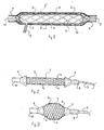
- the invention generally relates to a hydraulic or pneumatic drive device which is essentially comprised of a hermetically-sealable chamber 1, which is bounded by a wall 1 ⁇ from substantially resiliently distortable material, and of flexible, substantially unstretchable spiral-wound filaments 5 and 6, such as steel wires, which extend substantially next to one another in the form of a casing about and contacting said wall 1 ⁇ .
- One portion 5 from said filaments are wound leftwards, while the other portion 6 thereof are wound rightwards, and this with a suitable play in such a way that two arbitrary crossing filaments 5 and 6 can undergo some angular relative displacement relative to one another.
- each filament 5 and 6 on the one side of chamber 1 is fixed relative to a working point 9, while the other end thereof on the opposite side of said wall 1, is fixed relative to another working point 10.
- the wall 1 ⁇ from chamber 1 is distortable at least along one direction cross-wise to the line joining the working points 9 and 10, in such a way that by regulating the gas or liquid pressure inside chamber 1, a relative displacement of said working points occurs.
- the working points 9 and 10 are movable relative to one another between two end positions: an inactive position as shown in figure 2, and a terminal active position as shown in figure 3.
- the gas or liquid pressure inside chamber 1 is minimum and the slope angle of the spiral-wound filaments 5 and 6 is preferably larger than 36°, more particularly between 50 and 80°, while in the terminal active position, said angle is approximately about 36°.
- said chamber preferably has for most applications being considered, the shape of a revolution body the revolution surface of which is formed by the flexible resiliently-distortable wall 1 ⁇ , with the working points 9 and 10 lying on the revolution axis thereof on either side of said body, and the filaments 5 and 6 are wound spiral-like along said axis thereabout.
- the wall 1 ⁇ is comprised of a cylinder-like tube from flexible, resilient material, both ends of which are closed by a plug 8.
- a rigid transition piece 4 is provided, which is comprised of a truncated cone-shaped sleeve which is slipped over the spiral-wound filaments.
- said transition piece 4 clamps the wall 1 ⁇ as well as the filaments 5 and 6 on the plugs 8. Moreover, to insure the tightness, the transition piece has an inward-facing ring-like indentation 11 which engages a similar indentation in the plugs 8.
- the free ends of the spiral-wound filaments are twisted together in bundles, in the shape of a flattened cable, and thus form said working points 9 and 10, wherein a fastening is for example provided.
- a double wall which is formed on the one hand by the above-described wall 1 ⁇ , and on the other hand by an outer casing 2 also from a flexible, resiliently-distortable material, wherebetween said filaments 5 and 6 are arranged together with a lubricant 16, such as talc or graphite, which allows to dramatically minimize the mutual friction between filaments 5 and 6, and serves simultaneously as protection for wall 1 ⁇ .
- a lubricant 16 such as talc or graphite
- a distortable material layer may possibly be provided together with or instead of a lubricant, between the rightward-wound and leftward-wound filaments.
- the slope angles of the leftward-wound and righward-wound filaments are preferably the same.
- the spiral filaments 5 and 6 When an overpressure prevails inside chamber 1, the spiral filaments 5 and 6 will lie in the most-extended condition, in other words the number windings per length unit will be lowest. In such a case, the crossing angle ⁇ between the leftward-wound and rightward-wound filaments will be as small as possible (see figure 4).
- the spacing between the working points 9 and 10 is thereby the widest and the device lies in inactive position.
- the force being generated on the working points 9 and 10 is largest when said crossing angle ⁇ is smallest and decreases as said angle increases.
- the operation goes on until the crossing angle ⁇ between the spiral filaments has reached about 108°C. At this moment, the pulling force between the working points becomes zero and the diameter of the expanded cylinder-like wall 1 ⁇ the largest.
- the drive device then lies in said terminal active position. It has been determined that in such position, the spacing reduction between the working points 9 and 10 for a 108° crossing angle is brought down to 40% of the original spcaing between said working points, that is in said inactive position.
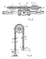
- Figure 8 relates to a valve which can be controlled completely automatically by means of two drive devices according to the invention arranged in the extension of one another, by regulating the pressure inside the chambers 1 from both devices lying in the extension of one another.
- Said latter devices are hingedly mounted in the working points thereof, to one another and relative to the valve, in such a way that the operating arm 12 thereof can perform an angular displacement between two end positions as shown by dot-and-dash line 12 ⁇ . Both drive devices undergo thereby some rotation about the fixed fastening points 13 and 14 thereof.
- Figure 9 shows an apparatus which is for example usable as hoisting device, automatic door opener, etc...
- the hose-like chamber 1 bulges and undergoes a shortening about 40%, whereby the movable working point 10 undergoes an upwards displacement together with a rotation of the pulley wheel 15.
- said device may advantageously be used in the robot domain, for building all kinds of prostheses, such as artificial limbs.
Landscapes
- Engineering & Computer Science (AREA)
- Chemical & Material Sciences (AREA)
- Analytical Chemistry (AREA)
- Physics & Mathematics (AREA)
- Fluid Mechanics (AREA)
- Mechanical Engineering (AREA)
- General Engineering & Computer Science (AREA)
- Actuator (AREA)
Applications Claiming Priority (2)
| Application Number | Priority Date | Filing Date | Title |
|---|---|---|---|
| BE217191 | 1986-09-22 | ||
| BE0/217191A BE905465A (nl) | 1986-09-22 | 1986-09-22 | Hydraulische of pneumatische aandrijfinrichting. |
Publications (2)
| Publication Number | Publication Date |
|---|---|
| EP0261721A2 true EP0261721A2 (de) | 1988-03-30 |
| EP0261721A3 EP0261721A3 (de) | 1988-11-09 |
Family
ID=3844081
Family Applications (1)
| Application Number | Title | Priority Date | Filing Date |
|---|---|---|---|
| EP87201738A Withdrawn EP0261721A3 (de) | 1986-09-22 | 1987-09-11 | Hydraulische oder pneumatische Antriebseinrichtung |
Country Status (3)
| Country | Link |
|---|---|
| US (1) | US4841845A (de) |
| EP (1) | EP0261721A3 (de) |
| BE (1) | BE905465A (de) |
Cited By (11)
| Publication number | Priority date | Publication date | Assignee | Title |
|---|---|---|---|---|
| WO1992015790A1 (de) * | 1991-03-06 | 1992-09-17 | Ralph Wenzel | Vorrichtung zum erzeugen einer zugkraft mittels druckmittel |
| CH685388A5 (de) * | 1992-07-27 | 1995-06-30 | Branislav Previsic Mile Previs | Zugvorrichtung. |
| EP0677662A1 (de) * | 1994-04-11 | 1995-10-18 | Werner Homann | Muskelartiges Kraftelement |
| DE19643649C1 (de) * | 1996-10-22 | 1998-02-19 | Homann Werner Dipl Ing Fh | Stellantrieb zur Umwandlung der Energie eines Fluids in eine mechanische Kraft |
| US5937732A (en) * | 1996-10-22 | 1999-08-17 | Homann; Werner | Actuator for converting fluid energy into a mechanical force |
| DE10313189A1 (de) * | 2003-03-25 | 2004-10-07 | Acts Gmbh & Co. Kg | Vorrichtung zum Anheben einer Kraftfahrzeugfronthaube mit einem Wegbegrenzungseelment |
| DE102004045130A1 (de) * | 2004-09-17 | 2006-03-23 | Wolter, Dietmar, Prof. Dr.Med. | Kraftübertragungselement |
| DE102005008017A1 (de) * | 2005-02-22 | 2006-08-31 | Bayerische Motoren Werke Ag | Durch Fluidkraft aktivierbare Betätigungseinrichtung |
| DE102005008016A1 (de) * | 2005-02-22 | 2006-08-31 | Bayerische Motoren Werke Ag | Betätigungseinrichtung mit einem sich zwischen zwei Kopfstücken erstreckenden anisotropen Hohlkörper, insbesondere Schlauchkörper |
| WO2007035976A2 (de) | 2005-09-30 | 2007-04-05 | Paolo Ferrara | Vorrichtung zum flexibel steuerbaren bewegen von menschen oder gegenständen |
| US7283196B2 (en) | 2002-03-22 | 2007-10-16 | Ecsibeo Ab | Liquid crystal device, a method for producing a liquid crystal device and a method for controlling a liquid crystal device |
Families Citing this family (39)
| Publication number | Priority date | Publication date | Assignee | Title |
|---|---|---|---|---|
| US5014515A (en) * | 1989-05-30 | 1991-05-14 | Welch Allyn, Inc. | Hydraulic muscle pump |
| JP2846344B2 (ja) * | 1989-06-19 | 1999-01-13 | 株式会社ブリヂストン | 弾性伸長体を用いたアクチュエータ |
| JPH0324304A (ja) * | 1989-06-20 | 1991-02-01 | Bridgestone Corp | 弾性伸長体を用いたアクチュエータ |
| JPH03113104A (ja) * | 1989-09-25 | 1991-05-14 | Bridgestone Corp | 湾曲可能なアクチュエータ |
| US5014600A (en) * | 1990-02-06 | 1991-05-14 | Welch Allyn, Inc. | Bistep terminator for hydraulic or pneumatic muscle |
| US5031510A (en) * | 1990-03-22 | 1991-07-16 | Welch Allyn, Inc. | Evacuation spring for hydraulic/pneumatic muscle |
| US5351602A (en) * | 1992-08-05 | 1994-10-04 | The United States Of America As Represented By The Secretary Of The Army | Jointed assembly actuated by fluid pressure |
| GB2328981A (en) * | 1997-09-05 | 1999-03-10 | Richard Martin Greenhill | Improved component of mechanical actuator |
| US6067892A (en) | 1998-03-18 | 2000-05-30 | Erickson; Joel R. | Artificial muscle actuator assembly |
| GB2335467A (en) * | 1998-03-20 | 1999-09-22 | Richard Martin Greenhill | Improved mechanical actuator |
| US6209443B1 (en) | 1998-07-09 | 2001-04-03 | Hiflex Technologies Inc. | Low pressure actuator |
| DE20004326U1 (de) * | 2000-03-08 | 2000-06-21 | Festo AG & Co, 73734 Esslingen | Betätigungseinrichtung |
| CA2343480C (en) * | 2001-04-06 | 2008-09-23 | Hiflex Technologies Inc. | Chain and cartridge actuator |
| DE10139861B4 (de) * | 2001-08-14 | 2004-07-01 | Daimlerchrysler Ag | Radaufhängung eines Kraftfahrzeugs |
| DE20115847U1 (de) * | 2001-09-26 | 2001-12-13 | Loctite Deutschland GmbH, 81925 München | Vorrichtung zur Ventilbetätigung und zum Stellen des Ventilhubs |
| DE20205654U1 (de) * | 2002-04-12 | 2002-07-04 | FESTO AG & Co., 73734 Esslingen | Fluidbetätigter Kontraktionsantrieb und zugehöriger Kontraktionsschlauch |
| US6868773B2 (en) * | 2002-08-13 | 2005-03-22 | Electro Cam Corporation | Fluidic actuator |
| US6901840B1 (en) * | 2002-10-29 | 2005-06-07 | Joseph S. Yatsko | Angular actuator and control therefor |
| JP2004244081A (ja) * | 2003-02-17 | 2004-09-02 | Toyo Jidoki Co Ltd | 袋のシール装置 |
| US7353715B2 (en) * | 2004-12-03 | 2008-04-08 | General Electric Company | System, apparatus and method for testing under applied and reduced loads |
| US8210051B2 (en) * | 2004-12-03 | 2012-07-03 | General Electric Company | System and method for cyclic testing |
| US8210050B2 (en) * | 2004-12-03 | 2012-07-03 | General Electric Company | Apparatus and system for cyclic testing |
| WO2006080088A1 (ja) * | 2005-01-31 | 2006-08-03 | Squse Inc. | アクチュエータ、駆動装置、及びハンド装置 |
| DE102005055210A1 (de) * | 2005-11-19 | 2007-05-24 | Zf Friedrichshafen Ag | Automatisiertes Schaltgetriebe und automatisierte Reibungskupplung |
| RU2319043C2 (ru) * | 2006-01-27 | 2008-03-10 | Эдуард Дмитриевич Житников | Эластичный пневматический цилиндр |
| GB2467762B (en) * | 2009-02-13 | 2013-08-14 | Shadow Robot Company Ltd | Robotic musculo-skeletal jointed structures |
| US9541196B2 (en) | 2009-11-13 | 2017-01-10 | The Boeing Company | Miniature McKibben actuator |
| US9097081B2 (en) * | 2011-11-07 | 2015-08-04 | Schlumberger Technology Corporation | Differential pressure actuator |
| US10132336B1 (en) | 2013-04-22 | 2018-11-20 | Vecna Technologies, Inc. | Actuator for rotating members |
| US9440361B1 (en) * | 2013-06-28 | 2016-09-13 | Daniel Theobald | Activation element and method |
| US10280951B2 (en) | 2014-03-02 | 2019-05-07 | Drexel University | Articulating devices |
| WO2016093038A1 (ja) | 2014-12-11 | 2016-06-16 | R.U.Technologies株式会社 | アシスト装置、アシスト衣服、及びアシスト方法 |
| CN106426140B (zh) * | 2015-08-28 | 2019-01-08 | 朱正直 | 一种人工肌肉及使用人工肌肉的机器 |
| DE112016004162B4 (de) * | 2015-09-14 | 2025-06-12 | Koganei Corporation | McKIBBEN KÜNSTLICHER MUSKEL |
| US10340057B2 (en) | 2015-11-24 | 2019-07-02 | Cisco Technology, Inc. | Unified power and data cable |
| DE102015225143B4 (de) * | 2015-12-14 | 2019-09-05 | Fraunhofer-Gesellschaft zur Förderung der angewandten Forschung e.V. | Linearaktor |
| JP6889992B2 (ja) * | 2016-09-02 | 2021-06-18 | 株式会社ブリヂストン | 流体圧アクチュエータ |
| CA3188140A1 (en) | 2020-06-24 | 2021-12-30 | Winston Products Llc | Expandable hose |
| CN116619346B (zh) * | 2023-05-24 | 2025-08-05 | 西南交通大学 | 一种内置预应变的负压气动人工肌肉驱动器 |
Family Cites Families (23)
| Publication number | Priority date | Publication date | Assignee | Title |
|---|---|---|---|---|
| CA509387A (en) * | 1955-01-25 | H. Morin Alexandre | Elastic diaphragm | |
| DE225834C (de) * | ||||
| US1025986A (en) * | 1911-07-29 | 1912-05-14 | Post & Lester Company | Bulb. |
| DE503775C (de) * | 1929-03-11 | 1930-07-26 | Dimitri Sensaud De Lavaud | Vorrichtung zur Erzeugung eines UEber- oder Unterdruckes in Gasen oder Fluessigkeiten |
| US2328970A (en) * | 1941-01-24 | 1943-09-07 | Robert H Farquhar | Pneumatic jack |
| US2532143A (en) * | 1946-04-06 | 1950-11-28 | Jack & Heintz Prec Ind Inc | Accumulator |
| US2483088A (en) * | 1946-06-20 | 1949-09-27 | Haven Hugh De | Tensioning device for producing a linear pull |
| US2584431A (en) * | 1946-06-24 | 1952-02-05 | Walker Mfg Company Of Wisconsi | Expansible wall receptacle |
| FR1003449A (fr) * | 1947-01-03 | 1952-03-18 | Membrane en forme de fourreau dont la paroi est constituée par des éléments d'étanchéité et par des éléments de traction | |
| US2789580A (en) * | 1953-11-18 | 1957-04-23 | Standard Thomson Corp | Mechanical transducer with expansible cavity |
| US2844126A (en) * | 1955-01-20 | 1958-07-22 | Clevite Corp | Fluid actuated motor system and stroking device |
| FR1187335A (fr) * | 1957-11-27 | 1959-09-09 | Pneumatiques Caoutchouc Mfg | Système transformateur de travail par tuyau déformable |
| GB1216321A (en) * | 1967-01-26 | 1970-12-16 | Audco Ltd | Improvements in and relating to fluid power actuators |
| US3481254A (en) * | 1967-08-14 | 1969-12-02 | United Aircraft Corp | Composite structure |
| US3579412A (en) * | 1968-05-29 | 1971-05-18 | Nasa | Fluid impervious barrier including liquid metal alloy and method of making same |
| US3645173A (en) * | 1969-10-20 | 1972-02-29 | Trish Energetics Inc | Fluid actuator |
| US3561330A (en) * | 1969-11-24 | 1971-02-09 | Stanley R Rich | Fluid operable motor |
| DE2701843A1 (de) * | 1977-01-18 | 1978-07-20 | Dunlop Ltd | Verstaerkter schlauch |
| JPS5881205A (ja) * | 1981-11-09 | 1983-05-16 | Shunji Hirabayashi | 流体圧アクチユエ−タ |
| EP0123558B1 (de) * | 1983-04-25 | 1990-11-14 | Bridgestone Corporation | Pneumatisches Stellglied für Manipulatoren |
| US4733603A (en) * | 1983-11-21 | 1988-03-29 | Mirko Kukolj | Axially contractable actuator |
| JPS60227003A (ja) * | 1984-04-25 | 1985-11-12 | Bridgestone Corp | 高忠実性の内圧応動弾性収縮筒 |
| US4664232A (en) * | 1984-04-25 | 1987-05-12 | Bridgestone Corporation | Brake device for robot arm |
-
1986
- 1986-09-22 BE BE0/217191A patent/BE905465A/nl not_active IP Right Cessation
-
1987
- 1987-09-11 EP EP87201738A patent/EP0261721A3/de not_active Withdrawn
- 1987-09-21 US US07/099,007 patent/US4841845A/en not_active Expired - Fee Related
Cited By (15)
| Publication number | Priority date | Publication date | Assignee | Title |
|---|---|---|---|---|
| WO1992015790A1 (de) * | 1991-03-06 | 1992-09-17 | Ralph Wenzel | Vorrichtung zum erzeugen einer zugkraft mittels druckmittel |
| CH685388A5 (de) * | 1992-07-27 | 1995-06-30 | Branislav Previsic Mile Previs | Zugvorrichtung. |
| EP0677662A1 (de) * | 1994-04-11 | 1995-10-18 | Werner Homann | Muskelartiges Kraftelement |
| DE19643649C1 (de) * | 1996-10-22 | 1998-02-19 | Homann Werner Dipl Ing Fh | Stellantrieb zur Umwandlung der Energie eines Fluids in eine mechanische Kraft |
| US5937732A (en) * | 1996-10-22 | 1999-08-17 | Homann; Werner | Actuator for converting fluid energy into a mechanical force |
| US7283196B2 (en) | 2002-03-22 | 2007-10-16 | Ecsibeo Ab | Liquid crystal device, a method for producing a liquid crystal device and a method for controlling a liquid crystal device |
| US7295272B2 (en) | 2002-03-22 | 2007-11-13 | Ecsibeo Ppf1 Ab | Liquid crystal device, a method for producing a liquid crystal device and method for controlling a liquid crystal device |
| DE10313189A1 (de) * | 2003-03-25 | 2004-10-07 | Acts Gmbh & Co. Kg | Vorrichtung zum Anheben einer Kraftfahrzeugfronthaube mit einem Wegbegrenzungseelment |
| DE10313189B4 (de) * | 2003-03-25 | 2016-07-07 | Magna Electronics Europe Gmbh & Co.Kg | Vorrichtung zum Anheben einer Kraftfahrzeugfronthaube mit einem Wegbegrenzungseelment |
| DE102004045130A1 (de) * | 2004-09-17 | 2006-03-23 | Wolter, Dietmar, Prof. Dr.Med. | Kraftübertragungselement |
| DE102005008016A1 (de) * | 2005-02-22 | 2006-08-31 | Bayerische Motoren Werke Ag | Betätigungseinrichtung mit einem sich zwischen zwei Kopfstücken erstreckenden anisotropen Hohlkörper, insbesondere Schlauchkörper |
| DE102005008017A1 (de) * | 2005-02-22 | 2006-08-31 | Bayerische Motoren Werke Ag | Durch Fluidkraft aktivierbare Betätigungseinrichtung |
| WO2007035976A3 (de) * | 2005-09-30 | 2007-05-24 | Paolo Ferrara | Vorrichtung zum flexibel steuerbaren bewegen von menschen oder gegenständen |
| WO2007035976A2 (de) | 2005-09-30 | 2007-04-05 | Paolo Ferrara | Vorrichtung zum flexibel steuerbaren bewegen von menschen oder gegenständen |
| US8021288B2 (en) | 2005-09-30 | 2011-09-20 | Paolo Ferrara | Device for moving people or objects in a flexible controllable manner |
Also Published As
| Publication number | Publication date |
|---|---|
| US4841845A (en) | 1989-06-27 |
| EP0261721A3 (de) | 1988-11-09 |
| BE905465A (nl) | 1987-01-16 |
Similar Documents
| Publication | Publication Date | Title |
|---|---|---|
| EP0261721A2 (de) | Hydraulische oder pneumatische Antriebseinrichtung | |
| US5067390A (en) | Double-acting flexible wall actuator | |
| EP0161750B1 (de) | Betätigungseinrichtung | |
| US4777868A (en) | Flexible actuator | |
| US5251538A (en) | Prehensile apparatus | |
| US5158005A (en) | Actuator using elastic extensible member | |
| EP0162539B1 (de) | Bremsvorrichtung, insbesondere für einen Roboterarm | |
| US5562275A (en) | Radially and longitudinally indeformable flexible spindle | |
| SG144732A1 (en) | Improvements relating to hose | |
| JPH03113104A (ja) | 湾曲可能なアクチュエータ | |
| WO2007129094A3 (en) | Improvements relating to hose | |
| US12202134B2 (en) | Bending operation mechanism | |
| JPS60146695A (ja) | ロボツトハンド | |
| JPH04145206A (ja) | 中空型弾性伸縮体 | |
| GB2285300A (en) | Vibration reduction | |
| WO1985000870A1 (en) | Method of depositing a membrane within a conduit | |
| TW202216082A (zh) | 關節功能部 | |
| JP2001012414A (ja) | 流体作動式回転駆動装置 | |
| JPH04304983A (ja) | 管内移動装置及びその操縦方法 | |
| WO2024048300A1 (ja) | アクチュエータ把持力推定装置、アクチュエータ把持力推定方法 | |
| WO2024048299A1 (ja) | アクチュエータ湾曲内側長測定装置、アクチュエータ湾曲内側長測定方法 | |
| EP0163370A1 (de) | Betätigungseinrichtung | |
| JP2018115754A (ja) | アクチュエータ、アクチュエータ装置、およびアクチュエータの駆動方法 | |
| JPS61262205A (ja) | 湾曲自在なアクチユエ−タ | |
| JPS63500607A (ja) | 垂直導管の引張装置 |
Legal Events
| Date | Code | Title | Description |
|---|---|---|---|
| PUAI | Public reference made under article 153(3) epc to a published international application that has entered the european phase |
Free format text: ORIGINAL CODE: 0009012 |
|
| AK | Designated contracting states |
Kind code of ref document: A2 Designated state(s): AT CH DE ES FR GB GR IT LI LU NL SE |
|
| PUAL | Search report despatched |
Free format text: ORIGINAL CODE: 0009013 |
|
| AK | Designated contracting states |
Kind code of ref document: A3 Designated state(s): AT CH DE ES FR GB GR IT LI LU NL SE |
|
| 17P | Request for examination filed |
Effective date: 19890503 |
|
| 17Q | First examination report despatched |
Effective date: 19900723 |
|
| STAA | Information on the status of an ep patent application or granted ep patent |
Free format text: STATUS: THE APPLICATION IS DEEMED TO BE WITHDRAWN |
|
| 18D | Application deemed to be withdrawn |
Effective date: 19930401 |