EP0261726A2 - Pistons - Google Patents
Pistons Download PDFInfo
- Publication number
- EP0261726A2 EP0261726A2 EP87201756A EP87201756A EP0261726A2 EP 0261726 A2 EP0261726 A2 EP 0261726A2 EP 87201756 A EP87201756 A EP 87201756A EP 87201756 A EP87201756 A EP 87201756A EP 0261726 A2 EP0261726 A2 EP 0261726A2
- Authority
- EP
- European Patent Office
- Prior art keywords
- component
- crown
- piston according
- annular
- skirt
- Prior art date
- Legal status (The legal status is an assumption and is not a legal conclusion. Google has not performed a legal analysis and makes no representation as to the accuracy of the status listed.)
- Granted
Links
- 239000000919 ceramic Substances 0.000 claims abstract description 24
- 238000002485 combustion reaction Methods 0.000 claims abstract description 15
- PXHVJJICTQNCMI-UHFFFAOYSA-N Nickel Chemical compound [Ni] PXHVJJICTQNCMI-UHFFFAOYSA-N 0.000 claims abstract description 14
- 229910000838 Al alloy Inorganic materials 0.000 claims abstract description 11
- 239000010959 steel Substances 0.000 claims abstract description 9
- 229910045601 alloy Inorganic materials 0.000 claims abstract description 8
- 239000000956 alloy Substances 0.000 claims abstract description 8
- 229910000831 Steel Inorganic materials 0.000 claims abstract description 7
- 229910052759 nickel Inorganic materials 0.000 claims abstract description 7
- 238000003466 welding Methods 0.000 claims abstract description 7
- 229910052581 Si3N4 Inorganic materials 0.000 claims abstract description 6
- HQVNEWCFYHHQES-UHFFFAOYSA-N silicon nitride Chemical compound N12[Si]34N5[Si]62N3[Si]51N64 HQVNEWCFYHHQES-UHFFFAOYSA-N 0.000 claims abstract description 6
- 239000002131 composite material Substances 0.000 claims abstract description 3
- 229910010293 ceramic material Inorganic materials 0.000 claims description 7
- 229910052751 metal Inorganic materials 0.000 claims description 4
- 239000002184 metal Substances 0.000 claims description 4
- 239000000306 component Substances 0.000 claims 13
- XEEYBQQBJWHFJM-UHFFFAOYSA-N Iron Chemical compound [Fe] XEEYBQQBJWHFJM-UHFFFAOYSA-N 0.000 abstract description 12
- 229910052742 iron Inorganic materials 0.000 abstract description 6
- 229910000851 Alloy steel Inorganic materials 0.000 abstract description 2
- 238000010894 electron beam technology Methods 0.000 description 5
- 238000000034 method Methods 0.000 description 4
- 238000009413 insulation Methods 0.000 description 3
- 238000005304 joining Methods 0.000 description 3
- 239000000463 material Substances 0.000 description 3
- CWYNVVGOOAEACU-UHFFFAOYSA-N Fe2+ Chemical compound [Fe+2] CWYNVVGOOAEACU-UHFFFAOYSA-N 0.000 description 2
- 229910001069 Ti alloy Inorganic materials 0.000 description 2
- MCMNRKCIXSYSNV-UHFFFAOYSA-N Zirconium dioxide Chemical compound O=[Zr]=O MCMNRKCIXSYSNV-UHFFFAOYSA-N 0.000 description 2
- 238000010276 construction Methods 0.000 description 2
- 230000000694 effects Effects 0.000 description 2
- 238000012986 modification Methods 0.000 description 2
- 230000004048 modification Effects 0.000 description 2
- 241001125877 Gobio gobio Species 0.000 description 1
- 238000005266 casting Methods 0.000 description 1
- 239000000567 combustion gas Substances 0.000 description 1
- 239000000470 constituent Substances 0.000 description 1
- 238000005260 corrosion Methods 0.000 description 1
- 230000007797 corrosion Effects 0.000 description 1
- 238000009792 diffusion process Methods 0.000 description 1
- 230000003628 erosive effect Effects 0.000 description 1
- 238000005242 forging Methods 0.000 description 1
- 239000000446 fuel Substances 0.000 description 1
- 238000010348 incorporation Methods 0.000 description 1
- 230000007774 longterm Effects 0.000 description 1
- 238000003754 machining Methods 0.000 description 1
- 238000004519 manufacturing process Methods 0.000 description 1
- 229910001092 metal group alloy Inorganic materials 0.000 description 1
- 150000002739 metals Chemical class 0.000 description 1
- 230000003647 oxidation Effects 0.000 description 1
- 238000007254 oxidation reaction Methods 0.000 description 1
- 238000004886 process control Methods 0.000 description 1
- 229910000601 superalloy Inorganic materials 0.000 description 1
Images


Classifications
-
- F—MECHANICAL ENGINEERING; LIGHTING; HEATING; WEAPONS; BLASTING
- F02—COMBUSTION ENGINES; HOT-GAS OR COMBUSTION-PRODUCT ENGINE PLANTS
- F02F—CYLINDERS, PISTONS OR CASINGS, FOR COMBUSTION ENGINES; ARRANGEMENTS OF SEALINGS IN COMBUSTION ENGINES
- F02F7/00—Casings, e.g. crankcases
- F02F7/0085—Materials for constructing engines or their parts
- F02F7/0087—Ceramic materials
-
- F—MECHANICAL ENGINEERING; LIGHTING; HEATING; WEAPONS; BLASTING
- F02—COMBUSTION ENGINES; HOT-GAS OR COMBUSTION-PRODUCT ENGINE PLANTS
- F02F—CYLINDERS, PISTONS OR CASINGS, FOR COMBUSTION ENGINES; ARRANGEMENTS OF SEALINGS IN COMBUSTION ENGINES
- F02F3/00—Pistons
- F02F3/10—Pistons having surface coverings
- F02F3/12—Pistons having surface coverings on piston heads
- F02F3/14—Pistons having surface coverings on piston heads within combustion chambers
-
- F—MECHANICAL ENGINEERING; LIGHTING; HEATING; WEAPONS; BLASTING
- F02—COMBUSTION ENGINES; HOT-GAS OR COMBUSTION-PRODUCT ENGINE PLANTS
- F02F—CYLINDERS, PISTONS OR CASINGS, FOR COMBUSTION ENGINES; ARRANGEMENTS OF SEALINGS IN COMBUSTION ENGINES
- F02F2200/00—Manufacturing
- F02F2200/04—Forging of engine parts
-
- F—MECHANICAL ENGINEERING; LIGHTING; HEATING; WEAPONS; BLASTING
- F05—INDEXING SCHEMES RELATING TO ENGINES OR PUMPS IN VARIOUS SUBCLASSES OF CLASSES F01-F04
- F05C—INDEXING SCHEME RELATING TO MATERIALS, MATERIAL PROPERTIES OR MATERIAL CHARACTERISTICS FOR MACHINES, ENGINES OR PUMPS OTHER THAN NON-POSITIVE-DISPLACEMENT MACHINES OR ENGINES
- F05C2201/00—Metals
- F05C2201/02—Light metals
- F05C2201/021—Aluminium
-
- F—MECHANICAL ENGINEERING; LIGHTING; HEATING; WEAPONS; BLASTING
- F05—INDEXING SCHEMES RELATING TO ENGINES OR PUMPS IN VARIOUS SUBCLASSES OF CLASSES F01-F04
- F05C—INDEXING SCHEME RELATING TO MATERIALS, MATERIAL PROPERTIES OR MATERIAL CHARACTERISTICS FOR MACHINES, ENGINES OR PUMPS OTHER THAN NON-POSITIVE-DISPLACEMENT MACHINES OR ENGINES
- F05C2201/00—Metals
- F05C2201/04—Heavy metals
- F05C2201/0433—Iron group; Ferrous alloys, e.g. steel
- F05C2201/0448—Steel
-
- F—MECHANICAL ENGINEERING; LIGHTING; HEATING; WEAPONS; BLASTING
- F05—INDEXING SCHEMES RELATING TO ENGINES OR PUMPS IN VARIOUS SUBCLASSES OF CLASSES F01-F04
- F05C—INDEXING SCHEME RELATING TO MATERIALS, MATERIAL PROPERTIES OR MATERIAL CHARACTERISTICS FOR MACHINES, ENGINES OR PUMPS OTHER THAN NON-POSITIVE-DISPLACEMENT MACHINES OR ENGINES
- F05C2251/00—Material properties
- F05C2251/04—Thermal properties
- F05C2251/042—Expansivity
Definitions
- the present invention relates to pistons and to methods of manufacture of such pistons for internal combustion engines and particularly to pistons having insulating crowns to reduce the heat loss from the engine combustion processes.
- a piston for an internal combustion engine comprises a crown component and a skirt component wherein the crown component consists of an iron-based or nickel-based alloy annular portion having fitted directly therein a ceramic insert, the crown component being joined to the skirt component by an annular composite laminated member of steel and aluminium alloy the steel of the laminated member being energy beam welded to the annular portion of the crown component and the aluminium alloy of the laminated member being energy beam welded to the skirt component there being after welding a sealed, hollow, annular chamber disposed at the junction between the crown component and the skirt component.
- the iron-based or nickel-based alloy annular portion may also include a hollow, sealed cavity within the portion.
- the cavity may extend around the whole annular portion and itself be annular in form.
- the cavity may be of varying cross-section around its length.
- the cavity may be formed by the joining together of two component parts to form the annular portion.
- the ceramic insert may also include a combustion bowl in, for example, diesel applications.
- the bowl may have any desired configuration and be positioned symmetrically or asymmetrical with regard to either the piston crown or the insert.
- the ceramic insert may itself comprise two or more different ceramics.
- the main body of the insert may comprise silicon nitride, for example, whilst the surfaces thereof may be coated with partially stabilised zirconia, for example.
- Energy beam welding may be by either electron beam or laser beam.
- a diesel engine piston is shown generally at 10.
- the piston 10 comprises a crown component 11 and a skirt component 12.
- the crown component 11 is formed by an annular ring portion 13 made from an iron or nickel based alloy.
- Shrink-fitted to the ring portion 13 is a ceramic insert 14 having a combustion bowl 15 formed therein.
- the ceramic material of the insert 14 may, for example, comprise silicon nitride or partially stabilised zironia (PSZ) or a combination thereof.
- PSZ partially stabilised zironia
- the skirt component 12 comprises the normal gudgeon pin bores 16, bosses 17 and piston ring grooves 18. Formed in the upper planar surface 19 of the skirt component 12 are depressions 20 and 21.
- Depression 20 is annular in form.
- the lower end of the annular ring portion 13 has a radially thickened portion 22 to which is joined by means of an electron beam or laser weld 23 an annular, laminated bimetallic joining member 24.
- the member 24 comprises a steel layer 25 and an aluminium alloy layer 26 which have been joined together at the interface 27 by a pressure welding technique such as roll bonding.
- the crown component 11 is then joined to the upper surface 19 of the skirt component 12 by a second annular electron beam or laser formed weld 28 between the aluminium alloy of the annular member 24 and the aluminium alloy of the skirt 12.
- Formed at the junction of the steel 25 of the annular member 24 and the thickened portion 22 of the annular ring 13 is the upper piston ring groove 29.
- annular air-gap 31 is formed at the junction of the ring portion 13, ceramic insert 14, upper face 19 and annular joining member 24.
- the air-gap 31 further significantly enhances the heat insulating qualities of the piston and serves to reduce thermally induced stresses at the junction of dissimilar materials.
- the ceramic bowl insert may be shrink-fitted after the member 13 has been joined to the skirt component 12.
- the second material may be coated on some of the outer surfaces of the main body of the insert.
- the main body may comprise silicon nitride coated with plasma-sprayed PSZ at the regions where the insert contacts the annular portion and the piston skirt component.
- annular ring portion 13 further includes a lower base member 40 the crown component 11 thus incorporating a sealed air gap 31.
- the crown component 11 is joined to the skirt portion 12 in a similar manner to that of Figure 1.
- Formed between the lower face 41 of the base member 40 and the upper face 19 of the skirt component 12 is a sealed air gap 42 which further enhances the insulating properties of the piston.
- the embodiment shown in Figure 3 has an annular ring portion 13 which is itself fabricated from two constituent parts.
- the ring 13 comprises an upper eccentric annular member 50 having an eccentric annular channel 51 therein and a lower annular member 52, which in this case has a shallow eccentric annular channel 53 therein which co-operates with the channel 51 of the upper member 50.
- the two members 50 and 52 are joined by an electron beam weld 55 to form a hollow, eccentric annular ring 13 having a sealed, eccentric annular chamber 56 therein.
- Shrink-fitted into the ring 13 is a symmetrical ceramic insert 14.
- the crown component 11 so formed is joined to the skirt component 12 as described above with reference to Figure 1.
- the upper annular member 50 may be formed by casting, forging or machining from a heat and oxidation-resistant iron or nickel-based alloy whilst the lower member 52 may be made from a less highly alloyed and cheaper ferrous material.
- both members may be produced from titanium alloy, the electron beam weld 55 being optionally replaced by a diffusion bond.
- the use of titanium alloys may be advantageous because of their favourably low coefficients of thermal expansion and also because of their relatively low density.
- the offset combustion chamber of Figure 3 may, of course, be achieved by means of a symmetrical upper annular member 51 and providing a ceramic insert 14 itself having an offset combustion chamber.
- centrally positioned combustion chambers with respect to the piston crown may be produced by employing symmetrical annular members 50 and 52 and insert 14.
- Figure 4 shows a modification to the embodiment of Figure 3 in that the air gaps 20,21 are replaced by a ceramic disc 60 of particularly low thermal conductivity, for example, PSZ.
- the disc 60 is located in a recess 61 formed in the upper face 19 of the skirt component 12.
- the disc 60 may alternatively be located in a corresponding recess in the base of the insert 14 or may merely be located by interference between two substantially flat surfaces.
- the disc 60 may not necessarily comprise monolithic ceramic but may be formed from a steel, ferrous alloy or other metal alloy coated with PSZ and where the PSZ layer is placed in contact with the lower face of the insert 14.
- the embodiment of Figure 5 shows a further modification of the embodiment of Figure 3 in that the lower member 52 of the ring portion 13 further includes a base member 70 and consequent air chamber 71.
- the hollow ring member 13 of the embodiments shown in Figures 3, 4 and 5 further improve the heat insulation of the piston crown and, therefore, the performance of the piston.
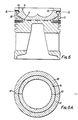
- the piston of Figures 6 and 6A again has a ring member 13 of fabricated construction. It comprises two substantially semi-circular halves 80 and 81 split about the faces 82 and 83.
- the ceramic insert 14 is held in the ring by welding together, preferably by a high energy beam method, of the two halves on the faces 82 and 83.
- the insert 14 is provided with a circumferential channel 85 which co-operates with an inturned flange 86 on the halves 80 and 81.
- This embodiment does not, therefore, rely only upon an interference shrink-fit between the ring 13 and insert 14.
- An additional annular air gap 31 is again formed between the crown and skirt portions. This construction is advantageous in that no metal is directly exposed to the combustion gases.
Landscapes
- Engineering & Computer Science (AREA)
- Chemical & Material Sciences (AREA)
- Combustion & Propulsion (AREA)
- Mechanical Engineering (AREA)
- General Engineering & Computer Science (AREA)
- Ceramic Engineering (AREA)
- Pistons, Piston Rings, And Cylinders (AREA)
Applications Claiming Priority (2)
| Application Number | Priority Date | Filing Date | Title |
|---|---|---|---|
| GB8622538 | 1986-09-18 | ||
| GB868622538A GB8622538D0 (en) | 1986-09-18 | 1986-09-18 | Pistons |
Publications (3)
| Publication Number | Publication Date |
|---|---|
| EP0261726A2 true EP0261726A2 (fr) | 1988-03-30 |
| EP0261726A3 EP0261726A3 (en) | 1988-09-21 |
| EP0261726B1 EP0261726B1 (fr) | 1991-04-10 |
Family
ID=10604415
Family Applications (1)
| Application Number | Title | Priority Date | Filing Date |
|---|---|---|---|
| EP87201756A Expired EP0261726B1 (fr) | 1986-09-18 | 1987-09-14 | Pistons |
Country Status (4)
| Country | Link |
|---|---|
| US (1) | US4838149A (fr) |
| EP (1) | EP0261726B1 (fr) |
| DE (1) | DE3769257D1 (fr) |
| GB (2) | GB8622538D0 (fr) |
Cited By (4)
| Publication number | Priority date | Publication date | Assignee | Title |
|---|---|---|---|---|
| EP0363190A3 (en) * | 1988-10-07 | 1990-07-04 | Ngk Insulators, Ltd. | Direct injection-type diesel engines |
| US4972898A (en) * | 1988-06-23 | 1990-11-27 | T & N Technology Limited | Method of forming a piston containing a cavity |
| CN101903632B (zh) * | 2007-12-20 | 2012-09-05 | 马勒国际公司 | 用于在内燃机用活塞上固定环形件的方法 |
| CN101213360B (zh) * | 2005-05-23 | 2013-01-09 | 费德罗-莫格尔公司 | 柴油机的涂层动力缸部件 |
Families Citing this family (40)
| Publication number | Priority date | Publication date | Assignee | Title |
|---|---|---|---|---|
| JPH02104950A (ja) * | 1988-10-14 | 1990-04-17 | Nissan Motor Co Ltd | 内燃機関のピストン |
| JPH0364654A (ja) * | 1989-07-31 | 1991-03-20 | Nissan Motor Co Ltd | 内燃機関用ピストン |
| JPH0668258B2 (ja) * | 1989-09-13 | 1994-08-31 | いすゞ自動車株式会社 | 断熱ピストンの構造 |
| DE4019983A1 (de) * | 1990-06-22 | 1992-01-02 | Kolbenschmidt Ag | Leichtmetallkolben |
| BR9004990A (pt) * | 1990-09-28 | 1992-03-31 | Metal Leve Sa | Processo de fabricacao de cabeca de embolo articulado e embolo articulado |
| JP2591872B2 (ja) * | 1991-08-26 | 1997-03-19 | 日本碍子株式会社 | 窒化珪素鋳ぐるみピストン |
| US5361740A (en) * | 1993-03-29 | 1994-11-08 | Jacobs Brake Technology Corporation | Mechanical assemblies with hardened bearing surfaces |
| DE69724035T2 (de) * | 1996-05-20 | 2004-02-19 | Yamaha Hatsudoki K.K., Iwata | Verfahren zur Herstellung einen Kolben für eine Brennkraftmaschine |
| US6003479A (en) * | 1997-05-12 | 1999-12-21 | Evans; Mark M. | Piston construction |
| US6223701B1 (en) | 1999-08-16 | 2001-05-01 | Caterpillar Inc. | Cooled one piece piston and method |
| US6327962B1 (en) | 1999-08-16 | 2001-12-11 | Caterpillar Inc. | One piece piston with supporting piston skirt |
| US6286414B1 (en) | 1999-08-16 | 2001-09-11 | Caterpillar Inc. | Compact one piece cooled piston and method |
| GB0015689D0 (en) * | 2000-06-28 | 2000-08-16 | Federal Mogul Technology Ltd | Manufacturing pistons |
| AU2002213255A1 (en) * | 2000-10-18 | 2002-04-29 | Federal Mogul Corporation | Multi-axially forged piston |
| DE10063568A1 (de) * | 2000-12-20 | 2002-07-04 | Mahle Gmbh | Kühlkanalkolben für einen Dieselmotor mit Direkteinspritzung mit einem Kolbendurchmesser von 100 mm |
| DE10110889C1 (de) * | 2001-03-07 | 2002-10-02 | Ks Kolbenschmidt Gmbh | Verfahren zur Herstellung eines Kühlkanalkolbens, sowie ein nach dem Verfahren hergestellter Kühlkanalkolben |
| US6862976B2 (en) | 2001-10-23 | 2005-03-08 | Federal-Mogul World Wide, Inc. | Monobloc piston |
| US8276563B2 (en) * | 2002-06-28 | 2012-10-02 | Cummins, Inc. | Internal combustion engine piston |
| EP1452250B1 (fr) * | 2003-03-01 | 2008-11-12 | KS Kolbenschmidt GmbH | Méthode de fabrication d'un piston à canal de refroidissement avec collet déformable |
| DE10315415A1 (de) * | 2003-04-04 | 2004-10-14 | Mahle Gmbh | Verfahren zur Herstellung von Kolben mit Muldenrandbewehrung für Verbrennungsmotoren |
| DE102004031513A1 (de) * | 2004-06-30 | 2006-01-26 | Ks Kolbenschmidt Gmbh | Verfahren zur Herstellung eines Kühlkanalkolbens für eine Brennkraftmaschine |
| DE102005061060A1 (de) * | 2005-12-21 | 2007-06-28 | Mahle International Gmbh | Kolben für einen Verbrennungsmotor und Verfahren zu seiner Herstellung |
| DE102008038325A1 (de) * | 2007-12-20 | 2009-06-25 | Mahle International Gmbh | Verfahren zum Befestigen eines Ringelementes auf einem Kolben für einen Verbrennungsmotor |
| BRPI0821738A2 (pt) * | 2007-12-21 | 2015-06-16 | Green Partners Technology Gmbh | Sistema de turbina a gás de ciclo aberto e fechado e semi-fechado de energia e de turbina de expansão e compressor de pistão de ciclo fechado, turbocompressor e métodos de produção de energia com turbina de gás de ciclo abreto, de compressão de gás de operação em turbocompressor e operação de sistema de motor |
| CA2710280A1 (fr) * | 2007-12-21 | 2009-07-09 | Green Partners Technology Holdings Gmbh | Systemes de turbines a gaz et procedes faisant appel a un dispositif de distribution de liquide vaporisable |
| US9856820B2 (en) | 2010-10-05 | 2018-01-02 | Mahle International Gmbh | Piston assembly |
| US8813357B2 (en) * | 2010-10-06 | 2014-08-26 | GM Global Technology Operations LLC | Piston with bi-metallic dome |
| BR112013025888A2 (pt) * | 2011-04-15 | 2018-06-05 | Federal Mogul Corp | pistão e método de fazer um pistão |
| US8973484B2 (en) | 2011-07-01 | 2015-03-10 | Mahle Industries Inc. | Piston with cooling gallery |
| US8671905B2 (en) | 2011-07-12 | 2014-03-18 | Mahle International Gmbh | Piston for an internal combustion engine and method for its production |
| DE102011107656A1 (de) * | 2011-07-12 | 2013-01-17 | Mahle International Gmbh | Verfahren zur Herstellung eines Kolbens für einen Verbrennungsmotor sowie Kolben für einen Verbrennungsmotor |
| DE102011119527A1 (de) * | 2011-11-26 | 2013-05-29 | Mahle International Gmbh | Kolben für einen Verbrennungsmotor und Verfahren zu seiner Herstellung |
| DE102013218709A1 (de) * | 2012-09-27 | 2014-03-27 | Ks Kolbenschmidt Gmbh | Zweiteilig aufgebauter Kolben einer Brennkraftmaschine |
| WO2015029117A1 (fr) * | 2013-08-26 | 2015-03-05 | 日本碍子株式会社 | Moteur à combustion interne |
| JP6281332B2 (ja) * | 2014-03-11 | 2018-02-21 | 日産自動車株式会社 | 内燃機関のピストン |
| WO2017176935A1 (fr) * | 2016-04-05 | 2017-10-12 | Federal-Mogul Llc | Piston avec insert thermiquement isolant et procédé de construction associé |
| EP3452712B1 (fr) | 2016-05-04 | 2024-11-20 | KS Kolbenschmidt GmbH | Piston |
| WO2017203779A1 (fr) * | 2016-05-27 | 2017-11-30 | 本田技研工業株式会社 | Piston et son procédé de fabrication |
| US10662892B2 (en) * | 2016-09-09 | 2020-05-26 | Caterpillar Inc. | Piston for internal combustion engine having high temperature-capable crown piece |
| CN109538370A (zh) * | 2017-09-21 | 2019-03-29 | 强莉莉 | 一种复合式活塞 |
Family Cites Families (19)
| Publication number | Priority date | Publication date | Assignee | Title |
|---|---|---|---|---|
| DE1777228A1 (de) * | 1968-09-28 | 1971-05-27 | Schmidt Gmbh Karl | Verfahren zum Verbinden unterschiedlicher Kolbenwerkstoffe |
| US4530884A (en) * | 1976-04-05 | 1985-07-23 | Brunswick Corporation | Ceramic-metal laminate |
| US4531269A (en) * | 1981-07-06 | 1985-07-30 | Deere & Company | Method of assembling an improved heat insulated piston |
| GB2125517B (en) * | 1982-08-20 | 1987-03-11 | Ae Plc | Pistons and methods for their manufacture |
| DE3329787A1 (de) * | 1982-08-20 | 1984-02-23 | AE PLC, Rugby, Warwickshire | Kolben und verfahren zu ihrer herstellung |
| GB2136720B (en) * | 1982-11-17 | 1985-12-18 | Ae Plc | Joining silicon nitride to metals |
| JPS59101566A (ja) * | 1982-12-03 | 1984-06-12 | Ngk Insulators Ltd | エンジン部品 |
| US4590901A (en) * | 1983-05-13 | 1986-05-27 | Gte Products Corporation | Heat insulated reciprocating component of an internal combustion engine and method of making same |
| US4531502A (en) * | 1983-05-18 | 1985-07-30 | Gte Products Corporation | Thermally insulated piston |
| JPS59224445A (ja) * | 1983-06-03 | 1984-12-17 | Ngk Spark Plug Co Ltd | ピストン |
| DE3330554A1 (de) * | 1983-08-24 | 1985-03-07 | Kolbenschmidt AG, 7107 Neckarsulm | Kolben fuer brennkraftmaschinen |
| EP0167523B1 (fr) * | 1983-12-27 | 1990-04-04 | Ford Motor Company Limited | Pistons composites et leur procede de fabrication |
| US4552057A (en) * | 1983-12-30 | 1985-11-12 | Gte Products Corporation | Thermally insulated piston |
| US4604945A (en) * | 1983-12-30 | 1986-08-12 | Gte Products Corporation | Thermally insulated piston |
| DE3404121A1 (de) * | 1984-02-07 | 1985-08-08 | M.A.N. Maschinenfabrik Augsburg-Nürnberg AG, 8900 Augsburg | Waermedaemmender kolben fuer verbrennungskraftmaschinen |
| JPS60175750A (ja) * | 1984-02-23 | 1985-09-09 | Ngk Insulators Ltd | セラミツクス鋳ぐるみピストン |
| JPS60190651A (ja) * | 1984-03-12 | 1985-09-28 | Ngk Insulators Ltd | エンジン用ピストンおよびその製造法 |
| JPS60190650A (ja) * | 1984-03-13 | 1985-09-28 | Ngk Insulators Ltd | エンジン用ピストンおよびその製造法 |
| JPS6223558A (ja) * | 1985-02-22 | 1987-01-31 | Tsutae Ishii | 内燃機関の防音型ピストン,ライナ−およびヘツド |
-
1986
- 1986-09-18 GB GB868622538A patent/GB8622538D0/en active Pending
-
1987
- 1987-09-14 GB GB8721583A patent/GB2196094B/en not_active Expired - Fee Related
- 1987-09-14 EP EP87201756A patent/EP0261726B1/fr not_active Expired
- 1987-09-14 DE DE8787201756T patent/DE3769257D1/de not_active Expired - Fee Related
- 1987-09-15 US US07/096,901 patent/US4838149A/en not_active Expired - Fee Related
Cited By (4)
| Publication number | Priority date | Publication date | Assignee | Title |
|---|---|---|---|---|
| US4972898A (en) * | 1988-06-23 | 1990-11-27 | T & N Technology Limited | Method of forming a piston containing a cavity |
| EP0363190A3 (en) * | 1988-10-07 | 1990-07-04 | Ngk Insulators, Ltd. | Direct injection-type diesel engines |
| CN101213360B (zh) * | 2005-05-23 | 2013-01-09 | 费德罗-莫格尔公司 | 柴油机的涂层动力缸部件 |
| CN101903632B (zh) * | 2007-12-20 | 2012-09-05 | 马勒国际公司 | 用于在内燃机用活塞上固定环形件的方法 |
Also Published As
| Publication number | Publication date |
|---|---|
| US4838149A (en) | 1989-06-13 |
| GB2196094B (en) | 1990-10-17 |
| GB8622538D0 (en) | 1986-10-22 |
| EP0261726A3 (en) | 1988-09-21 |
| EP0261726B1 (fr) | 1991-04-10 |
| DE3769257D1 (de) | 1991-05-16 |
| GB8721583D0 (en) | 1987-10-21 |
| GB2196094A (en) | 1988-04-20 |
Similar Documents
| Publication | Publication Date | Title |
|---|---|---|
| EP0261726A2 (fr) | Pistons | |
| KR100762527B1 (ko) | 직접 분사식 디젤 엔진용 냉각 채널 피스톤 | |
| WO2013013830A1 (fr) | Protection du rebord de cuvette et de la racine pour piston en aluminium | |
| US4137887A (en) | Pistons for internal combustion engines | |
| CA1249751A (fr) | Piston metal-ceramique et procede de fabrication | |
| EP1052435B1 (fr) | Support de segment de piston avec cavité de refroidissement et son procédé de fabrication | |
| US4590901A (en) | Heat insulated reciprocating component of an internal combustion engine and method of making same | |
| EP0155159A2 (fr) | Piston pour moteur à combustion interne et son procédé de fabrication | |
| EP0366410B1 (fr) | Article composite en céramique et métal soudé par friction et piston moulé comportant une pièce rapportée en céramique | |
| EP0167523B1 (fr) | Pistons composites et leur procede de fabrication | |
| US4608321A (en) | Ceramic and metal composite body | |
| US4292937A (en) | Piston for internal combustion engines | |
| GB2092709A (en) | Securing piston crown | |
| JP2920004B2 (ja) | セラミックスと金属の鋳ぐるみ複合体 | |
| JP3270937B2 (ja) | エンジンのシリンダヘッド構造 | |
| JP2659636B2 (ja) | ディーゼルエンジン用ピストンの中空耐摩環の形成方法 | |
| JPH063171B2 (ja) | セラミックスー金属の摩擦圧接体およびそれから成るセラミックス鋳ぐるみピストン | |
| JP2560402B2 (ja) | 内燃機関のピストン | |
| JPH04272455A (ja) | 燃焼室の製造法 | |
| EP0780554A1 (fr) | Construction de piston avec chambre de combustion calorifugée | |
| JPH08210178A (ja) | ライナ一体化シリンダブロック及びその製造方法 | |
| JPS6350420Y2 (fr) | ||
| JPS60240858A (ja) | エンジン用ピストン | |
| JPH0441961A (ja) | エンジン用シリンダブロック | |
| JPH05321757A (ja) | エンジン部品およびその製造法 |
Legal Events
| Date | Code | Title | Description |
|---|---|---|---|
| PUAI | Public reference made under article 153(3) epc to a published international application that has entered the european phase |
Free format text: ORIGINAL CODE: 0009012 |
|
| AK | Designated contracting states |
Kind code of ref document: A2 Designated state(s): DE FR IT SE |
|
| PUAL | Search report despatched |
Free format text: ORIGINAL CODE: 0009013 |
|
| AK | Designated contracting states |
Kind code of ref document: A3 Designated state(s): DE FR IT SE |
|
| 17P | Request for examination filed |
Effective date: 19880817 |
|
| 17Q | First examination report despatched |
Effective date: 19890417 |
|
| ITF | It: translation for a ep patent filed | ||
| GRAA | (expected) grant |
Free format text: ORIGINAL CODE: 0009210 |
|
| AK | Designated contracting states |
Kind code of ref document: B1 Designated state(s): DE FR IT SE |
|
| PG25 | Lapsed in a contracting state [announced via postgrant information from national office to epo] |
Ref country code: SE Effective date: 19910410 |
|
| REF | Corresponds to: |
Ref document number: 3769257 Country of ref document: DE Date of ref document: 19910516 |
|
| ET | Fr: translation filed | ||
| PLBE | No opposition filed within time limit |
Free format text: ORIGINAL CODE: 0009261 |
|
| STAA | Information on the status of an ep patent application or granted ep patent |
Free format text: STATUS: NO OPPOSITION FILED WITHIN TIME LIMIT |
|
| 26N | No opposition filed | ||
| PGFP | Annual fee paid to national office [announced via postgrant information from national office to epo] |
Ref country code: FR Payment date: 19940808 Year of fee payment: 8 |
|
| PGFP | Annual fee paid to national office [announced via postgrant information from national office to epo] |
Ref country code: DE Payment date: 19940824 Year of fee payment: 8 |
|
| PG25 | Lapsed in a contracting state [announced via postgrant information from national office to epo] |
Ref country code: FR Effective date: 19960531 |
|
| PG25 | Lapsed in a contracting state [announced via postgrant information from national office to epo] |
Ref country code: DE Effective date: 19960601 |
|
| REG | Reference to a national code |
Ref country code: FR Ref legal event code: ST |
|
| PG25 | Lapsed in a contracting state [announced via postgrant information from national office to epo] |
Ref country code: IT Free format text: LAPSE BECAUSE OF NON-PAYMENT OF DUE FEES;WARNING: LAPSES OF ITALIAN PATENTS WITH EFFECTIVE DATE BEFORE 2007 MAY HAVE OCCURRED AT ANY TIME BEFORE 2007. THE CORRECT EFFECTIVE DATE MAY BE DIFFERENT FROM THE ONE RECORDED. Effective date: 20050914 |