EP0261737A2 - Temperaturmesssonde zum Messen in Metallschmelzen - Google Patents
Temperaturmesssonde zum Messen in Metallschmelzen Download PDFInfo
- Publication number
- EP0261737A2 EP0261737A2 EP87201805A EP87201805A EP0261737A2 EP 0261737 A2 EP0261737 A2 EP 0261737A2 EP 87201805 A EP87201805 A EP 87201805A EP 87201805 A EP87201805 A EP 87201805A EP 0261737 A2 EP0261737 A2 EP 0261737A2
- Authority
- EP
- European Patent Office
- Prior art keywords
- tube
- probe according
- probe
- outer tube
- measuring element
- Prior art date
- Legal status (The legal status is an assumption and is not a legal conclusion. Google has not performed a legal analysis and makes no representation as to the accuracy of the status listed.)
- Withdrawn
Links
Images

Classifications
-
- G—PHYSICS
- G01—MEASURING; TESTING
- G01K—MEASURING TEMPERATURE; MEASURING QUANTITY OF HEAT; THERMALLY-SENSITIVE ELEMENTS NOT OTHERWISE PROVIDED FOR
- G01K1/00—Details of thermometers not specially adapted for particular types of thermometer
- G01K1/08—Protective devices, e.g. casings
- G01K1/10—Protective devices, e.g. casings for preventing chemical attack
- G01K1/105—Protective devices, e.g. casings for preventing chemical attack for siderurgical use
Definitions
- the invention relates to a probe for measuring in molten metal, which probe comprises a measuring element, a housing for said measuring element and electric conductors connecting to said measuring element, which extend outside the housing.
- the probes used up to now of this kind are suitable for a single dipping during some ten seconds at the most in molten metal, particularly molten steel. Each probe can thus only give an instant record of the temperature or the oxygen content of the molten metal for example.
- Probes of this kind for temperature measuring, respectively oxygen measuring have been put on the market by the Applicant, and described respectively in French Patent n o 2,382,683 and European Patent Application n o 0 108 431 of the Applicant.
- the probe should consequently be suitable for withstanding for the duration of a metallurgic process, dipping inside the molten metal. Such processes generally take up from one to eight hours.
- the invention has now for object to provide a probe for measuring inside molten metal, which can be dipped for a relatively long time in the molten metal and which is thus suitable for measuring continuously during the duration of a metallurgic process, and which is moreover relatively cheap.
- the housing for the measuring element comprises an inner tube from refractory material, wherein the measuring element is mounted, an outer tube which surrounds the inner tube at least over that probe portion which is to be dipped in the molten metal, and a filling of refractory material between the outer tube and the inner tube.
- the filling of refractory material forms a heat buffer which prevents strong temperature variations of the measuring element when dipping the probe in the molten metal or removing same therefrom, and which further excludes large temperature differentials between the measuring element portion lying inside the molten metal, and the portion thereof lying above said molten metal. Such temperature changes or such large temperature differentials can cause damage in the measuring element.
- the probe comprises a float which surrounds the outer tube.
- the probe Due to the float floating on the molten metal or more specifically on the slag which is formed on top of the molten metal, the probe will remain immersed always to the same depth during the measuring, in the molten metal. Temperature variations in the probe due to a continually changing immersion depth during the measuring are prevented with this embodiment. The float moreover forms an additional protection for the probe remainder in the location of the generally quite corrosive slag.
- the float may be formed directly on the outer tube, but the float is preferably manufactured as a loose part and is secured by a fastener to the outer tube.
- the filling between inner tube and outer tube is a bonded refractory powder.
- Said filling is preferably a resin-bonded sand.
- the inner tube is made from ceramics.
- the inner tube is perferably from aluminum oxide.
- Such aluminum oxide tubes are available in the trade and relatively unexpensive. Said tubes are however highly sensitive to heat shocks. Due to the above-described structure of the probe according to the invention, such relatively unexpensive tubes can still be used as encasement for the measuring element.
- the housing comprises an intermediate tube which surrounds locally the inner tube inside the outer tube and forms an additional protection for the measuring element and the inner tube level with that location where lies the slag formed on the molten metal.
- the outer tube is made from metal.
- the outer tube is preferably from steel.
- the housing comprises on that end away from the dipping end, which is to lie above the molten metal during the measuring, two top tubes surrounding one another, which surround the corresponding end of the measuring elements and of the electric conductors connecting thereto.
- the electric conductors extend out of the housing through a flexible hose.
- the flexible hose is preferably connected to a pressurized-air source, it opens up inside the housing and the housing is provided on that end away from the dipped end, with at least one opening for letting the pressurized air escape.
- the uppermost housing portion and mostly the electric conductors are cooled with pressurized air.
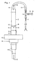
- the probe according to the figures is intended to be partly dipped into a molten metal bath the top surface of which is formed by a slag.
- the probe is dipped in a substantially vertical position with that end lying at the bottom in the figures, facing downwards. Said latter end is then also the dipping end.
- the ends of the probe or of components therefrom will then also be determined thereafter relative to said normal position when dipping and thus during the measuring, that is the position shown in the figures.
- the probe according to the figures is mainly comprised of a measuring element 1, a housing 2 for said measuring element 1, and two electric conductors 3 which connect to the measuring element 1.
- the measuring element 1 is a platinum-rhodium thermo-electric couple.
- the thin wires of said element extend through channels inside a small thin tube 4 from Al2O3.
- the hot junction 5 from said thermo-electric couple lies on the lowermost end outside the small tube 4.
- the cold junction lies at the top inside a small copper tube 6 which is mounted on the uppermost end of the small tube 4 and further forms a connector wherewith the thermo-electric couple wires are electrically connected with both copper conductors 3.
- the housing 2 comprises an inner tube 7 from Al2O3 which is closed at the bottom and includes the small tube 4 with the thermo-electric couple 1, and an outer tube 8 from steel.
- the space between the inner tube 7 and outer tube 8 is filled with a filling 9 from refractory material, namely a resin-impregnated sand, such as SiO2, chromite sand or zirconium sand.
- a resin-impregnated sand such as SiO2, chromite sand or zirconium sand.
- the impregnated sand is subjected after being brought between tubes 7 and 8, to a heat processing, for example during 10 minutes at a temperature of 150°C. The sand adheres thereby into a solid shape.
- the space between the innermost tube 7 and the small tube 4 is filled with a filling 10 from MgO powder.
- the filling 10 forms heat buffer around the thermo-electric couple 1
- the filling 10 enhances the stability and thermal balance of said thermo-electric couple.
- the inner tube 7 is surrounded over part of the height thereof by an intermediate tube 11 which is imbedded in said filling 9.
- Said intermediate tube 11 is also made from Al2O3 and insures additional protection for the measuring element 1, notably level with the slag over the molten metal.
- thermo-electric couple 1 To retain the response time of the thermo-electric couple 1 as short as possible, the lowermost end of said thermo-electric couple is naturally not surrounded by the intermediate tube 11.
- the outer tube 8 can have the same diameter over the whole length thereof. Said tube does however preferably have at the bottom, as shown in the figures, where no intermediate tube 11 is present, a smaller diameter because the response time of the thermo-electric couple 1 should be as short as possible.
- the outer tube 8 may then as shown, be comprised of two discrete tube parts with different diameter, whereby the lowermost tube part with smaller diameter is imbedded with the uppermost end thereof into the filling 9 lying between the uppermost portion of outer tube 8 and the inner tube 7.
- a characteristic of the invention is also that the outer tube 8 is surrounded by a float 12, 13 from refractory cement.
- Said float is comprised of a disc-shaped portion 12 and a round extension 13 connecting thereto on the lower side.
- the complete probe unit can float on the molten metal, whereby thus the float 12, 13 lies level with the top surface of the molten metal and thus level with the slag.
- the disc-shaped portion insures enough stability while the extension 13 is responsible for additional protection of the probe remainder in the location of the slag. Due to portion 13 having a smaller diameter, material is being saved and the float weight is reduced.
- the float 12, 13 can be secured directly on the outer tube 7, for example around a plate welded to said outer tube 7.
- the float 12, 13 is however preferably manufactured as in the embodiment shown in the figures, as a discrete part relative to the probe remainder. This does not only make the manufacture easier, but also the float 12,13 can be packaged and conveyed separately, which means place saving and reducing the danger of damaging the float.
- the float 12, 13 is secured to the outer tube 7 directly before putting the probe into use.
- L-shaped hooks 14 which project with one leg thereof on the top side, out of the disc-shaped portion. Said projecting legs are fastened by means of small screws 15 to the inner side of outer tube 8.
- the above-described housing portion, and thus notably the inner tube 7 and outer tube 8 extend from inside the molten metal up to above same when the probe floats therein, but not up to above the small tube 4 with the thermo-electric couple 1.
- thermo-electric couple 1 inclusive the small copper tube 6 are surrounded by two top tubes 16 and 17 surrounding one another, from aluminum.
- the lowermost end of the outermost top tube 17 fits into the open uppermost end of outer tube 8 and extends down to the level of the uppermost end of intermediate tube 11.
- Said outermost top tube 17 is fastened by means of small screws 18 to the outer tube 8 and the slit between the uppermost end of outer tube 8 and the outermost top tube 17 is sealed by a seal 19.
- the innermost top tube 16 projects at the top outside the outermost top tube 17 and extends at the bottom down to the uppermost end of intermediate tube 11.
- top tubes 16 and 17 are filled with a filling 20 from refractory powder, while at the top, said top tubes 16 and 17 are retained spaced from one another by spacers 21, without however the ring-shaped opening between the uppermost end of the outermost top tube 17 and innermost top tube 16 being completely closed.
- the uppermost end of the innermost top tube 16 is sealed with a seal 22.
- a flexible hose 23 wherethrough run both conductors 3.
- the flexible hose 23 is a synthetic material tube surrounded by a small woven glass-fiber tube.Said flexible hose 23 connects at a distance from housing 2, to the one arm of a T-shaped part 24.
- a second arm of T-shaped part 24 connects through a tube 25 to a pressurized-air pump 26.
- Both conductors 3 which run through flexible hose 23, further run through the third arm of T-shaped part 24, which arm is sealed at the end thereof about said conductors 3.
- the above-described probe has a quite simple structure and is relatively unexpensive.
- the probe can use cheap materials such as aluminum oxide for a number of small tubes, without any danger that such aluminum oxide tubes will burst due to heat shocks.
- the float insures an accurate and stable positioning of the probe and forms an additional protection for the probe remainder, mostly level with the slag.
- the disc-shaped portion also forms a kind of heat shield which limits the upwards radiation.
- the top tubes 16 and 17 reflect a major portion of the still-present heat radiation, whereby thus the uppermost portion of the thermo-electric couple and the conductors 3 are protected to the upmost. Such protection is further improved by the cooling with pressurized air.
- the resulting probe can be used during many hours to perform measurings.
- Said probe is thus operatingly reliable and relatively unexpensive.
- the ceramics for the small tube wherein the thermo-electric couple lies for the inner tube and for the outer tube should not necessarily be aluminum oxide.Other ceramics such as ZrO2 may also be used.
- the outer tube should not necessarily be manufactured from steel. It could also be made from another metal or ceramics.
- Said outer tube should not necessarily, as already stated, be comprised of two discrete parts.
- the float forms a part discrete from the probe remainder, the probe remainder itself may possibly be used by itself, without float.
- the measuring element does not either necessarily have to be a thermo-electric couple for measuring the temperature. It may also be an element for measuring an activity, for example the oxygen activity.
- the oxygen-activity measuring element can form a single unit with the inner tube and for example close off said inner tube at the dipped end.
Landscapes
- Physics & Mathematics (AREA)
- General Physics & Mathematics (AREA)
- Measuring Temperature Or Quantity Of Heat (AREA)
- Investigating And Analyzing Materials By Characteristic Methods (AREA)
- Continuous Casting (AREA)
Applications Claiming Priority (3)
| Application Number | Priority Date | Filing Date | Title |
|---|---|---|---|
| BE2061056 | 1986-09-22 | ||
| BE8661056A BE905463A (nl) | 1986-09-22 | 1986-09-22 | Sonde voor het meten in vloeibaar metaal. |
| BE905463 | 1986-09-22 |
Publications (2)
| Publication Number | Publication Date |
|---|---|
| EP0261737A2 true EP0261737A2 (de) | 1988-03-30 |
| EP0261737A3 EP0261737A3 (de) | 1990-03-07 |
Family
ID=25661195
Family Applications (1)
| Application Number | Title | Priority Date | Filing Date |
|---|---|---|---|
| EP87201805A Withdrawn EP0261737A3 (de) | 1986-09-22 | 1987-09-21 | Temperaturmesssonde zum Messen in Metallschmelzen |
Country Status (2)
| Country | Link |
|---|---|
| EP (1) | EP0261737A3 (de) |
| BE (1) | BE905463A (de) |
Families Citing this family (2)
| Publication number | Priority date | Publication date | Assignee | Title |
|---|---|---|---|---|
| AU612230B2 (en) * | 1988-02-16 | 1991-07-04 | Tempra Therm (Pty) Limited | Thermocouples |
| RU2206072C1 (ru) * | 2002-06-07 | 2003-06-10 | Сибирская аэрокосмическая академия им. акад. М.Ф.Решетнева | Защитный чехол термопары погружения |
Family Cites Families (5)
| Publication number | Priority date | Publication date | Assignee | Title |
|---|---|---|---|---|
| US3451863A (en) * | 1965-07-07 | 1969-06-24 | Bethlehem Steel Corp | Single-cast immersion thermocouple for continuous measurement of molten metal temperatures |
| US3544387A (en) * | 1966-12-28 | 1970-12-01 | Corning Glass Works | Expendable immersion thermocouple |
| US3647558A (en) * | 1967-06-26 | 1972-03-07 | Carborundum Co | Protected thermocouple and protection tube |
| FR2031966A5 (en) * | 1969-02-14 | 1970-11-20 | Siderurgie Fse Inst Rech | Pyrometric probe for continuously monitor- - ing temp of molten metal |
| GB2176611B (en) * | 1985-06-20 | 1989-07-19 | Thor Ceramics Ltd | Constant temperature probe |
-
1986
- 1986-09-22 BE BE8661056A patent/BE905463A/nl not_active IP Right Cessation
-
1987
- 1987-09-21 EP EP87201805A patent/EP0261737A3/de not_active Withdrawn
Also Published As
| Publication number | Publication date |
|---|---|
| EP0261737A3 (de) | 1990-03-07 |
| BE905463A (nl) | 1987-03-23 |
Similar Documents
| Publication | Publication Date | Title |
|---|---|---|
| EP0758445B1 (de) | Tauchsonde | |
| US5275488A (en) | BOF drop-in thermocouple | |
| AU4841696A (en) | Molten metal immersion probe | |
| US3374122A (en) | Expendable immersion thermocouple including weight | |
| US4428686A (en) | Thermocouple pyrometric apparatus | |
| JPS58135495A (ja) | 核燃料要素用の容器を収容するためのコンクリ−ト製防護ケ−シング | |
| US3308666A (en) | High temperature measuring devices | |
| US3647558A (en) | Protected thermocouple and protection tube | |
| GB2196430A (en) | Probe for measuring in molten metal | |
| EP0146205B1 (de) | Thermoelement zum wiederholten Gebrauch | |
| EP0261737A2 (de) | Temperaturmesssonde zum Messen in Metallschmelzen | |
| US9958427B2 (en) | Reverse filling carbon and temperature drop-in sensor | |
| US4995733A (en) | Measurement sensor for the detection of temperatures in metal or alloy melts | |
| US3398027A (en) | Pyrometric probe | |
| CA2199765A1 (en) | Method and apparatus for measurement of temperatures of molten aluminum and aluminum alloys | |
| US4433832A (en) | Metallurgical lance | |
| US3995918A (en) | System for bearing a nuclear reactor vessel cooled by liquid metal | |
| JPH09288000A (ja) | フロート式湯面検出装置 | |
| EP0045535B1 (de) | Tauchmesskopf zur Benützung in flüssigen Metallen | |
| PL149008B1 (en) | Measuring probe for determination of oxygen concentration at high temperatures | |
| JP2539861B2 (ja) | 溶融金属用連続測温管 | |
| JPS59147987A (ja) | 測温方法及び装置 | |
| JP2001183239A (ja) | 連続測温装置 | |
| US3544387A (en) | Expendable immersion thermocouple | |
| CN2213991Y (zh) | 连续测量连铸中间包内钢水温度的装置 |
Legal Events
| Date | Code | Title | Description |
|---|---|---|---|
| PUAI | Public reference made under article 153(3) epc to a published international application that has entered the european phase |
Free format text: ORIGINAL CODE: 0009012 |
|
| AK | Designated contracting states |
Kind code of ref document: A2 Designated state(s): AT CH DE FR IT LI LU NL SE |
|
| PUAL | Search report despatched |
Free format text: ORIGINAL CODE: 0009013 |
|
| RHK1 | Main classification (correction) |
Ipc: G01K 1/08 |
|
| STAA | Information on the status of an ep patent application or granted ep patent |
Free format text: STATUS: THE APPLICATION HAS BEEN WITHDRAWN |
|
| AK | Designated contracting states |
Kind code of ref document: A3 Designated state(s): AT CH DE FR IT LI LU NL SE |
|
| 18W | Application withdrawn |
Withdrawal date: 19900219 |
|
| RIN1 | Information on inventor provided before grant (corrected) |
Inventor name: CURE, OMER PAUL |