EP0261873A2 - Dispositif de préhension de charges pour chariot élévateur pour le maniement d'articles superposés avec dimensions différentes - Google Patents
Dispositif de préhension de charges pour chariot élévateur pour le maniement d'articles superposés avec dimensions différentes Download PDFInfo
- Publication number
- EP0261873A2 EP0261873A2 EP87308217A EP87308217A EP0261873A2 EP 0261873 A2 EP0261873 A2 EP 0261873A2 EP 87308217 A EP87308217 A EP 87308217A EP 87308217 A EP87308217 A EP 87308217A EP 0261873 A2 EP0261873 A2 EP 0261873A2
- Authority
- EP
- European Patent Office
- Prior art keywords
- pair
- clamp arms
- clamp
- clamping assembly
- actuators
- Prior art date
- Legal status (The legal status is an assumption and is not a legal conclusion. Google has not performed a legal analysis and makes no representation as to the accuracy of the status listed.)
- Granted
Links
Images
Classifications
-
- B—PERFORMING OPERATIONS; TRANSPORTING
- B66—HOISTING; LIFTING; HAULING
- B66F—HOISTING, LIFTING, HAULING OR PUSHING, NOT OTHERWISE PROVIDED FOR, e.g. DEVICES WHICH APPLY A LIFTING OR PUSHING FORCE DIRECTLY TO THE SURFACE OF A LOAD
- B66F9/00—Devices for lifting or lowering bulky or heavy goods for loading or unloading purposes
- B66F9/06—Devices for lifting or lowering bulky or heavy goods for loading or unloading purposes movable, with their loads, on wheels or the like, e.g. fork-lift trucks
- B66F9/075—Constructional features or details
- B66F9/12—Platforms; Forks; Other load supporting or gripping members
- B66F9/18—Load gripping or retaining means
- B66F9/184—Roll clamps
Definitions
- the present invention is directed to a lift truck-mounted load-handling clamp adapted for handling stacked loads of different sizes simultaneously. More particularly, the invention is directed to a clamp for handling stacked paper rolls of abbreviated length, referred to as split paper rolls.
- a relatively common requirement in the paper industry is the handling of split paper rolls which, because of their short length, are normally handled by a lift truck roll clamp in pairs having different diameters, stacked one atop the other.
- Lift truck paper roll clamps specially adapted for handling such stacked split rolls have been available in the past and consist of a pair of separately-actuated clamp arms on one side of the clamp, in opposed relation to a single, larger clamp arm assembly on the opposite side of the clamp.
- the separately-actuated arms give the clamp the ability to apply clamping force to two cylindrical objects of different diameters stacked one atop the other. Similar clamping capability can be required with respect to other types of loads, such as stacked bales or cartons of different sizes.
- a problem common to such previous clamps is their inability to attain the required clamping force on one of the separately-actuated clamp arms without attaining it also on the other separately-actuated arm. Stated another way, the resistance to clamping force from a load engaged by one of the clamp arms must be matched by a corresponding resistance to clamping force on the other arm before any clamping force can be applied.
- some of the prior split roll clamp structures merely have each separately-actuated arm powered by a separate hydraulic cylinder, the cylinders being connected in parallel to a source of pressurized fluid such that the pressure build-up in the two cylinders during clamping must be identical.
- Comparable alternative structures employ either a mechanical or hydraulic balance beam principle between a pair of clamp arms or load-engagement pads, so that the extent to which the unloaded arm or pad must close before clamping pressure can be built up on the loaded arm or pad is likewise limited. All of these structures, however, share the common problem that they are capable of handling a pair of split rolls only if the respective diameters of the two rolls are within a predetermined range of each other corresponding to the limited range of movement permitted between the two arms. Moreover, they share the further problem that, when only a single split roll is handled, it is subjected to twice the clamping force that exists when a pair of rolls are handled since all reaction to the clamping force must be absorbed by the single roll. This places undue and possibly damaging stress on the single roll, as well as on the particular clamp arm or pad which is engaging the roll.
- flow divider or combiner valves In many types of hydraulic mechanisms designed for a variety of purposes, it is common to use flow divider or combiner valves to regulate the flow of fluid to multiple actuators so as to cause them to move simultaneously and in proportion to each other. Such systems, however, are not adaptable to split paper roll clamps because the varying differences encountered between the diameters of pairs of stacked split rolls, as well as the requirement for engaging only a single split roll if necessary, require different proportions of movement between the respective clamp arms with each different load situation encountered. Flow divider and combiner valves are not readily adaptable to changeable proportions of movement.
- the present invention solves the foregoing problems by providing separately-movable clamp arms controlled by separate actuators selectively movable, by operation of a single common direction control valve, toward and away from an opposing clamp arm assembly.
- a regulator which requires the respective movements (or lack thereof) of the pair of clamp arms (or their load engagement pads) to be simultaneous.
- such regulator is a flow divider/combiner valve, although comparable hydraulic or electric regulators, in combination with hydraulic or electric actuators, can be used in equivalent structures.
- the present invention further provides means for automatically overriding the normal function of the regulator at the appropriate times.
- the overriding function occurs automatically in response to the attainment of a predetermined clamping force by one of the clamp arms, the overriding function permitting the other clamp arm to continue closing even though the first clamp arm can close no further. This is accomplished while maintaining the predetermined clamping force on the first clamp arm.
- the regulator upon opening of the clamp arms, the regulator requires simultaneous opening movement of the clamp arms so that they simultaneously release their clamped loads, but an overriding function permits the further opening of one arm when the other arm can open no further.
- the regulator and override system enables one clamp arm to engage a split paper roll or other type of load, such as a bale or carton, during closing and to apply full clamping pressure thereto immediately without any requirement that the other clamp arm close further or encounter any resistance to closing.
- the other clamp arm can be closed further into engagement with a smaller, second roll or other load while clamping pressure is maintained by the first clamp arm.
- both clamp arms simultaneously release their respective loads. Engagement and disengagement of single or plural loads, and disengagement therefrom, are thus accomplished quickly and effectively regardless of the extent of the difference in size of the plural loads, and regardless of the complete absence of a load.
- the invention is applicable to load clamps of all types, whether using pivotal arms or sliding arms, and for all types of loads whether of cylindrical or other shape.
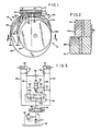
- An exemplary split paper roll clamp designated generally as l0 in FIG. l, is mounted on a vertically-reciprocating carriage l2 carried by a lift truck mast l4.
- the load clamp comprises a frame l6 mounted on the load carriage l2 connected either fixedly thereto or, as shown in FIG. l, by a rotator assembly l8.
- Pivotally mounted to the frame l6 at pivot points 20, 22 are a pair of opposed clamping assemblies designated generally as 24 and 26.
- the clamping assembly 24 comprises a pair of vertically-spaced clamp arms 28 and 30, having respective load engagement pads 28a and 30a, movable separately from each other relative to the frame l6 selectively toward and away from the opposed clamping assembly 26 under the control of fluid power actuators 32 and 34 respectively, each consisting of a double-acting hydraulic cylinder connected between the frame l6 and the respective clamp arm 28 or 30.
- the opposed clamping assembly 26 on the other hand, consists of only a single clamp arm 36 having an elongated load engagement pad 36a extending vertically so as to oppose the pads of both of the clamp arms 28 and 30.
- the clamp arm 36 pivots with respect to the frame l6 under the control of a further fluid power actuator 38.
- the arm 36 could be fixed with respect to the frame l6.
- the function of the load clamp l0 is to engage multiple split paper rolls, such as 40 and 42, of varying different diameters simultaneously so as to transport them from one location to another. It is also necessary that the clamp be capable of engaging and carrying only a single split paper roll, such as roll 40. Carrying of the rolls requires that each be engaged with sufficient clamping force, by the respective pads 28a, 30a and 36a, to be able to support the weight of the loads vertically.
- the clamping force with respect to pads 28a and 30a is supplied by the pressure of hydraulic fluid tending to extend hydraulic cylinders 32 and 34, respectively.
- a hydraulic pump 44 driven by the lift truck engine, delivers fluid under pressure from a hydraulic reservoir 46 to a manually-operable clamp arm directional control valve 48 shown in its centered, or unactuated, condition.
- a relief valve 50 sets an upper limit on the pressure of the fluid delivered by pump 44 by opening and bleeding fluid back to the reservoir 46 in response to excessive fluid pressure as determined by the variable setting of the relief valve 50.
- Closing of the clamp arms 28 and 30 is accomplished by the lift truck operator's manipulation of valve 48 so as to move its spool to the right as shown in FIG. 3.
- This delivers pressurized fluid to the input conduit 52 of a conventional flow divider/combiner valve 54 (such as that manufactured by Modular Controls of Villa Park, Illinois U.S.A. under Model No. FDA).
- the purpose of the valve 54 is to split the flow in input line 52 into a pair of emerging flows in lines 55 and 56 to ensure that the hydraulic cylinders 32 and 34 extend simultaneously, and thus that the clamp arms 28 and 30 advance simultaneously toward the opposed clamp arm assembly 36.
- the valve 54 causes the respective volumetric flow rates in conduits 55 and 56 to be proportional to each other and, assuming that the cylinders 32 and 34 are of the same diameter, preferably equal to each other. While the cylinders 32 and 34 are thus being extended, fluid from the rod end of each cylinder is being exhausted through a respective conduit 60, 58, and through the directional control valve 48 to the reservoir 46.
- clamp arm 28 would normally be the first to encounter resistance from the larger diameter roll 40. This resistance develops a higher pressure in conduit 56 than in conduit 55, and reduces the flow across restrictiveness 545mg of the valve 54. In response thereto, the valve 54 reduces restriction 545mg to accomplish a corresponding reduction in flow through restriction 545mg. When flow through restrictiveness 545mg ceases due to the inability of the cylinder 32 to extend further, restrictiveness 545mg is substantially closed, thereby likewise preventing further extension of cylinder 34 and further closure of clamp arm 30. At this point the clamp arm 30 has not yet engaged the smaller diameter roll 42.
- valve 64 permits further flow through restrictiveness 545mg and thus causes valve 54 to open restrictiveness 545mg to the extent that the flows through both restrictiveness are proportion', but with all of the flow being delivered to conduit 55.
- valve 64 While valve 64 is open, the predetermined clamping force is maintained on clamp arm 28 by a pilot operated check valve 72, but even in the absence thereof the clamping force would be maintained by the maintenance of the pressure in conduit 56 necessary to keep the sequence valve 64 open. Cylinder 34 continues to extend until encountering the resistance of roll 42, at which time clamping force is applied and the pressure in conduit 55 rises to a level equal to that in conduit 56, after which the directional control valve 48 may be centered and the rolls lifted.
- Relief valve 50 is set to open at a pressure sufficiently above that set by spring 62 of the sequence valve 64 (for example at least l00 psi higher) to insure that system pressure can always open the sequence valve, but sufficiently low to prevent damaging excessive clamping pressure on the rolls by continued actuation of the control valve 48.
- the exposure of the spring 62 to conduit 60 through drain line 63 during the foregoing operation does not effect the operation of the sequence valve 64 since conduit 60 is under low pressure when exhausting fluid during clamp arm closure.
- the flow divider valve 54 could be replaced with a pair of interconnected rotary flow regulators to ensure simultaneous flow through both conduits 55 and 56.
- the regulator 54 is shown interposed between the source of pressurized fluid and the cylinderderricks, it could alternatively be interposed in the exhaust conduits 58, 60, operating in a combining mode so as to require simultaneous exhaust flows from the cylinders 32 and 34, since controlling the exhaust of a double-acting cylinder is effective to control its input.
- clamp closing operation could be halted by deactivation of control valve 48 as soon as sufficient clamping pressure had been built up in conduit 56 upon initial engagement with the roll 40, and there would be no need to further extend cylinder 34 to further close clamp arm 30.
- the override valve 64 is responsive to the attainment of the predetermined clamping force by either one of the clamp arms 28 and 30 by virtue of its ability to sense pressure in either conduit 55 or condugouts 56 through shuttle valve 66.
- the clamp l0 had been inverted by rotator l8 such that the clamp arm 30 is in the lower position for engaging roll 40.
- the operation of arm 30 would be identical to that just described with respect to arm 28, and vice versa.
- valve 48 moves the spool of the control valve 48 to the left in FIG. 3, such that pressurized fluid from pump 44 is directed to the rod end of each hydraulic cylinder 32, 34. Pilot check valves 72 and 74 are unseated by the pressure in conduits 60 and 58, respectively, such that fluid can be exhausted simultaneously from the cylinders through conduits 55 and 56. Valve 54, acting now as a combiner valve, requires simultaneous flows through conduits 55 and 56 and, if such flows are not simultaneous and proportional, reduces the size of the restriction 545mg or 545mg having excessive flow.
- valve 54 acting in its combining mode, causes substantially simultaneous release of the two clamp arms 28 and 30.
- the clamp arms will open simultaneousEOP maintaining their different positions as long as the operator actuates the control valve 48.
- one clamp arm, such as 28 has reached Th full extent of its opening range, there can no longer be any flow exhausted from its cylinder 32 through restriction 545mg. Accordingly, the valve 54 tends to close the opposite restriction 545mg, likewise blocking the exhaust from cylinder 34, because of its requirement for simultaneousneoprene flows from the two cylinders. However, if it is desired that cylinder 34 be further retracted, the valve 54 can be overridden by the operator's continued actuation of control valve 48.
- valve 54 in its combinds mode would be to do so in substantially the same manner that it is overridden in its arm-like, dividing mode, i.e. provide a second shunting sequence valve such as 64 between the conduits 55 and 56 having a lower opening pressure setting than valve 64 and responsive to pressure from a second shuttle valve such as 66 interconnecting conduits 58 and 60.
- a simpler and more economical override system is used in FIG. 3 which relies merely on the ability of a convenetional flow divider/combiner valve such as 54 to permit opening of the restrictiveness 545mg, 545mg, when in its combinds mode, in response to pressure in conduit 55 or conduit 56 exceeding a predetermined limit.
Landscapes
- Engineering & Computer Science (AREA)
- Transportation (AREA)
- Structural Engineering (AREA)
- Civil Engineering (AREA)
- Life Sciences & Earth Sciences (AREA)
- Geology (AREA)
- Mechanical Engineering (AREA)
- Forklifts And Lifting Vehicles (AREA)
Applications Claiming Priority (2)
| Application Number | Priority Date | Filing Date | Title |
|---|---|---|---|
| US06/909,961 US4682931A (en) | 1986-09-22 | 1986-09-22 | Lift truck clamp for handling stacked loads of different sizes |
| US909961 | 1986-09-22 |
Publications (3)
| Publication Number | Publication Date |
|---|---|
| EP0261873A2 true EP0261873A2 (fr) | 1988-03-30 |
| EP0261873A3 EP0261873A3 (en) | 1989-10-04 |
| EP0261873B1 EP0261873B1 (fr) | 1992-08-19 |
Family
ID=25428110
Family Applications (1)
| Application Number | Title | Priority Date | Filing Date |
|---|---|---|---|
| EP87308217A Expired EP0261873B1 (fr) | 1986-09-22 | 1987-09-17 | Dispositif de préhension de charges pour chariot élévateur pour le maniement d'articles superposés avec dimensions différentes |
Country Status (5)
| Country | Link |
|---|---|
| US (1) | US4682931A (fr) |
| EP (1) | EP0261873B1 (fr) |
| JP (1) | JPH0631157B2 (fr) |
| DE (1) | DE3781230T2 (fr) |
| FI (1) | FI87345C (fr) |
Cited By (1)
| Publication number | Priority date | Publication date | Assignee | Title |
|---|---|---|---|---|
| DE4323328A1 (de) * | 1993-07-07 | 1995-01-12 | Schering Ag | Anbaugerät für Flurförderzeuge |
Families Citing this family (19)
| Publication number | Priority date | Publication date | Assignee | Title |
|---|---|---|---|---|
| US4907834A (en) * | 1988-02-29 | 1990-03-13 | Xerox Corporation | Multi-finger hydraulic end effector |
| GB2234957B (en) * | 1989-08-07 | 1994-03-23 | Totall Products Ltd | Apparatus for handling packaged bottles,cans,or the like |
| US5558380A (en) * | 1994-09-19 | 1996-09-24 | Deere & Company | Logging grapple |
| JPH09129783A (ja) * | 1995-10-31 | 1997-05-16 | Nec Corp | 樹脂封止型半導体装置およびその製造方法 |
| US5984617A (en) * | 1998-05-11 | 1999-11-16 | Cascade Corporation | Clamp for handling stacked loads of different sizes at different maximum clamping forces |
| US6318949B1 (en) | 2000-07-07 | 2001-11-20 | Cascade Corporation | Clamp for handling stacked loads of different sizes |
| US7056078B2 (en) * | 2003-09-24 | 2006-06-06 | Cascade Corporation | Hydraulically-synchronized clamp for handling stacked loads different sizes |
| ITMI20051256A1 (it) * | 2005-07-04 | 2007-01-05 | Auramo Oy | Gruppo idraulico di controllo dei bracci di una pinza e pinza comprendente tale gruppo idraulico |
| US7934758B2 (en) * | 2007-03-30 | 2011-05-03 | Caterpillar Inc. | Systems and methods for connecting and adapting a grapple assembly |
| EP2325499A1 (fr) | 2009-11-19 | 2011-05-25 | Bosch Rexroth Oil Control S.p.A. | Vanne équilibrée de pression pour deux cylindres fonctionnant en parallèle |
| US10087958B2 (en) | 2012-04-19 | 2018-10-02 | Cascade Corporation | Fluid power control system for mobile load handling equipment |
| US9114963B2 (en) * | 2013-02-26 | 2015-08-25 | Cascade Corporation | Clamping surface positioning system for mobile load-handling clamps |
| JP6136775B2 (ja) * | 2013-08-30 | 2017-05-31 | 株式会社ダイフク | 搬送装置 |
| US10494241B2 (en) * | 2016-09-16 | 2019-12-03 | Cascade Corporation | Hydraulic clamping systems having load side-shifting variably responsive to load weight |
| US10654690B2 (en) | 2018-06-30 | 2020-05-19 | Nhon Hoa Nguyen | Automatic locking mechanism and clamping devices with automatic locking mechanism |
| CN113260586B (zh) | 2019-01-04 | 2023-06-16 | 康宁股份有限公司 | 用于将工件保持在工作取向的流体操作的夹持设备和方法 |
| DE102019201599A1 (de) * | 2019-02-07 | 2020-08-13 | Bhs Intralogistics Gmbh | Überführungsanordnung |
| US12269713B2 (en) | 2020-12-21 | 2025-04-08 | Kenneth Brandon HOMEWOOD | Lifting clamp |
| US12304790B1 (en) | 2021-07-20 | 2025-05-20 | Shaw Industries Group, Inc. | Clamp adapter for lift vehicle to facilitate lifting of malleable objects |
Family Cites Families (11)
| Publication number | Priority date | Publication date | Assignee | Title |
|---|---|---|---|---|
| US2706060A (en) * | 1952-02-23 | 1955-04-12 | John J Ferrario | Apparatus for lifting and transporting cylindrical articles |
| FR1285165A (fr) * | 1961-03-30 | 1962-02-16 | Ruhr Intrans Hubstapler G M B | Procédé et pince à pierres pour l'enlèvement des cales de pierres moulées |
| US3203567A (en) * | 1962-02-23 | 1965-08-31 | Huitfeldt Paul Latham | Multiple roll clamp arms |
| GB985159A (en) * | 1963-09-20 | 1965-03-03 | Allis Chalmers Mfg Co | Control system for lift truck attachment |
| US3583586A (en) * | 1969-02-06 | 1971-06-08 | Jerry Fred Burton | Lift truck apparatus for manipulating storage drums |
| US3990594A (en) * | 1975-08-29 | 1976-11-09 | Cascade Corporation | Fluid-actuated clamping apparatus and circuit |
| US4127205A (en) * | 1977-09-19 | 1978-11-28 | Cascade Corporation | Lift truck load clamp for handling paper rolls |
| US4318661A (en) * | 1980-03-24 | 1982-03-09 | Dozier Equipment International Company | Drum handling device for forklift |
| US4397495A (en) * | 1981-06-29 | 1983-08-09 | Clark Equipment Company | Automatic grip control circuit for a grapple mechanism |
| JPS5845296U (ja) * | 1981-09-19 | 1983-03-26 | 株式会社豊田自動織機製作所 | ロ−ルクランプ装置 |
| FR2578824B1 (fr) * | 1985-03-15 | 1988-04-08 | Mennesson Jean Francois | Procede et dispositifs de prehension et de manutention de produits en vrac |
-
1986
- 1986-09-22 US US06/909,961 patent/US4682931A/en not_active Expired - Lifetime
-
1987
- 1987-09-17 DE DE8787308217T patent/DE3781230T2/de not_active Expired - Lifetime
- 1987-09-17 EP EP87308217A patent/EP0261873B1/fr not_active Expired
- 1987-09-21 JP JP62235036A patent/JPH0631157B2/ja not_active Expired - Fee Related
- 1987-09-22 FI FI874124A patent/FI87345C/fi not_active IP Right Cessation
Cited By (1)
| Publication number | Priority date | Publication date | Assignee | Title |
|---|---|---|---|---|
| DE4323328A1 (de) * | 1993-07-07 | 1995-01-12 | Schering Ag | Anbaugerät für Flurförderzeuge |
Also Published As
| Publication number | Publication date |
|---|---|
| EP0261873B1 (fr) | 1992-08-19 |
| FI874124A0 (fi) | 1987-09-22 |
| DE3781230T2 (de) | 1993-02-11 |
| FI874124L (fi) | 1988-03-23 |
| FI87345B (fi) | 1992-09-15 |
| EP0261873A3 (en) | 1989-10-04 |
| US4682931A (en) | 1987-07-28 |
| JPH0631157B2 (ja) | 1994-04-27 |
| FI87345C (fi) | 1992-12-28 |
| JPS63134500A (ja) | 1988-06-07 |
| DE3781230D1 (de) | 1992-09-24 |
Similar Documents
| Publication | Publication Date | Title |
|---|---|---|
| US4682931A (en) | Lift truck clamp for handling stacked loads of different sizes | |
| US5984617A (en) | Clamp for handling stacked loads of different sizes at different maximum clamping forces | |
| DE69930074T2 (de) | Adaptives Lastgreifsystem | |
| CN109562520B (zh) | 具有可变负载重量响应的负载侧移的液压夹紧系统 | |
| CN108025440B (zh) | 具有带有多个可伸缩延伸级段的负载夹持液压缸的夹具 | |
| US4177000A (en) | Rotatable load clamp adapted for selective load positioning in response to selective rotational positioning of clamp | |
| US5558380A (en) | Logging grapple | |
| US6318949B1 (en) | Clamp for handling stacked loads of different sizes | |
| US7056078B2 (en) | Hydraulically-synchronized clamp for handling stacked loads different sizes | |
| US4313633A (en) | Self adjusting actuator system | |
| US4226403A (en) | Overload protection device in air-operated lifting devices | |
| RU2158220C1 (ru) | Гидравлический привод стрелового самоходного крана | |
| US4170434A (en) | Load handling apparatus | |
| US3334756A (en) | Boom lift control system | |
| US20090050413A1 (en) | Clamp force control | |
| JPH06144795A (ja) | 流体動作積荷取扱クランプ | |
| EP1481938B1 (fr) | Grappin de levage de charges | |
| WO1981000249A1 (fr) | Systeme d'actionnement autoreglable | |
| JPH0462997B2 (fr) |
Legal Events
| Date | Code | Title | Description |
|---|---|---|---|
| PUAI | Public reference made under article 153(3) epc to a published international application that has entered the european phase |
Free format text: ORIGINAL CODE: 0009012 |
|
| AK | Designated contracting states |
Kind code of ref document: A2 Designated state(s): DE FR GB IT NL SE |
|
| PUAL | Search report despatched |
Free format text: ORIGINAL CODE: 0009013 |
|
| AK | Designated contracting states |
Kind code of ref document: A3 Designated state(s): DE FR GB IT NL SE |
|
| 17P | Request for examination filed |
Effective date: 19900308 |
|
| 17Q | First examination report despatched |
Effective date: 19910704 |
|
| GRAA | (expected) grant |
Free format text: ORIGINAL CODE: 0009210 |
|
| ITF | It: translation for a ep patent filed | ||
| AK | Designated contracting states |
Kind code of ref document: B1 Designated state(s): DE FR GB IT NL SE |
|
| ET | Fr: translation filed | ||
| REF | Corresponds to: |
Ref document number: 3781230 Country of ref document: DE Date of ref document: 19920924 |
|
| PLBE | No opposition filed within time limit |
Free format text: ORIGINAL CODE: 0009261 |
|
| STAA | Information on the status of an ep patent application or granted ep patent |
Free format text: STATUS: NO OPPOSITION FILED WITHIN TIME LIMIT |
|
| PGFP | Annual fee paid to national office [announced via postgrant information from national office to epo] |
Ref country code: FR Payment date: 19930808 Year of fee payment: 7 |
|
| 26N | No opposition filed | ||
| PGFP | Annual fee paid to national office [announced via postgrant information from national office to epo] |
Ref country code: SE Payment date: 19930813 Year of fee payment: 7 |
|
| PGFP | Annual fee paid to national office [announced via postgrant information from national office to epo] |
Ref country code: NL Payment date: 19930930 Year of fee payment: 7 |
|
| PG25 | Lapsed in a contracting state [announced via postgrant information from national office to epo] |
Ref country code: SE Effective date: 19940918 |
|
| EAL | Se: european patent in force in sweden |
Ref document number: 87308217.6 |
|
| PG25 | Lapsed in a contracting state [announced via postgrant information from national office to epo] |
Ref country code: NL Effective date: 19950401 |
|
| NLV4 | Nl: lapsed or anulled due to non-payment of the annual fee | ||
| PG25 | Lapsed in a contracting state [announced via postgrant information from national office to epo] |
Ref country code: FR Effective date: 19950531 |
|
| EUG | Se: european patent has lapsed |
Ref document number: 87308217.6 |
|
| REG | Reference to a national code |
Ref country code: FR Ref legal event code: ST |
|
| REG | Reference to a national code |
Ref country code: GB Ref legal event code: IF02 |
|
| PGFP | Annual fee paid to national office [announced via postgrant information from national office to epo] |
Ref country code: GB Payment date: 20060925 Year of fee payment: 20 |
|
| PGFP | Annual fee paid to national office [announced via postgrant information from national office to epo] |
Ref country code: IT Payment date: 20060930 Year of fee payment: 20 |
|
| PGFP | Annual fee paid to national office [announced via postgrant information from national office to epo] |
Ref country code: DE Payment date: 20061031 Year of fee payment: 20 |
|
| REG | Reference to a national code |
Ref country code: GB Ref legal event code: PE20 |
|
| PG25 | Lapsed in a contracting state [announced via postgrant information from national office to epo] |
Ref country code: GB Free format text: LAPSE BECAUSE OF EXPIRATION OF PROTECTION Effective date: 20070916 |