EP0261973A1 - Dispositif et procédé de traitement de particules fines - Google Patents
Dispositif et procédé de traitement de particules fines Download PDFInfo
- Publication number
- EP0261973A1 EP0261973A1 EP87308473A EP87308473A EP0261973A1 EP 0261973 A1 EP0261973 A1 EP 0261973A1 EP 87308473 A EP87308473 A EP 87308473A EP 87308473 A EP87308473 A EP 87308473A EP 0261973 A1 EP0261973 A1 EP 0261973A1
- Authority
- EP
- European Patent Office
- Prior art keywords
- fine particles
- nozzle
- reaction
- gas
- starting material
- Prior art date
- Legal status (The legal status is an assumption and is not a legal conclusion. Google has not performed a legal analysis and makes no representation as to the accuracy of the status listed.)
- Granted
Links
- 239000010419 fine particle Substances 0.000 title claims abstract description 53
- 238000000034 method Methods 0.000 title claims description 15
- 230000008569 process Effects 0.000 title claims description 7
- 238000006243 chemical reaction Methods 0.000 claims abstract description 74
- 239000007858 starting material Substances 0.000 claims abstract description 60
- 230000037361 pathway Effects 0.000 claims abstract description 9
- 239000000758 substrate Substances 0.000 claims description 9
- 239000007789 gas Substances 0.000 description 38
- 239000011882 ultra-fine particle Substances 0.000 description 17
- 239000011248 coating agent Substances 0.000 description 9
- 238000000576 coating method Methods 0.000 description 9
- 238000010574 gas phase reaction Methods 0.000 description 9
- 239000000203 mixture Substances 0.000 description 8
- 230000001276 controlling effect Effects 0.000 description 7
- 238000004381 surface treatment Methods 0.000 description 7
- 230000015572 biosynthetic process Effects 0.000 description 6
- 239000000463 material Substances 0.000 description 6
- 239000010410 layer Substances 0.000 description 5
- BLRPTPMANUNPDV-UHFFFAOYSA-N Silane Chemical compound [SiH4] BLRPTPMANUNPDV-UHFFFAOYSA-N 0.000 description 4
- 239000012159 carrier gas Substances 0.000 description 4
- WMIYKQLTONQJES-UHFFFAOYSA-N hexafluoroethane Chemical compound FC(F)(F)C(F)(F)F WMIYKQLTONQJES-UHFFFAOYSA-N 0.000 description 4
- 238000002156 mixing Methods 0.000 description 4
- 230000003647 oxidation Effects 0.000 description 4
- 238000007254 oxidation reaction Methods 0.000 description 4
- -1 polyethylene Polymers 0.000 description 4
- PZPGRFITIJYNEJ-UHFFFAOYSA-N disilane Chemical compound [SiH3][SiH3] PZPGRFITIJYNEJ-UHFFFAOYSA-N 0.000 description 3
- 230000004048 modification Effects 0.000 description 3
- 238000012986 modification Methods 0.000 description 3
- 238000001179 sorption measurement Methods 0.000 description 3
- 238000011144 upstream manufacturing Methods 0.000 description 3
- XKRFYHLGVUSROY-UHFFFAOYSA-N Argon Chemical compound [Ar] XKRFYHLGVUSROY-UHFFFAOYSA-N 0.000 description 2
- XEEYBQQBJWHFJM-UHFFFAOYSA-N Iron Chemical compound [Fe] XEEYBQQBJWHFJM-UHFFFAOYSA-N 0.000 description 2
- 239000000919 ceramic Substances 0.000 description 2
- 230000008859 change Effects 0.000 description 2
- 238000009792 diffusion process Methods 0.000 description 2
- 239000012530 fluid Substances 0.000 description 2
- 239000007791 liquid phase Substances 0.000 description 2
- 239000002245 particle Substances 0.000 description 2
- 238000006303 photolysis reaction Methods 0.000 description 2
- 230000015843 photosynthesis, light reaction Effects 0.000 description 2
- 230000002265 prevention Effects 0.000 description 2
- 238000009834 vaporization Methods 0.000 description 2
- 229920000178 Acrylic resin Polymers 0.000 description 1
- 239000004925 Acrylic resin Substances 0.000 description 1
- OKTJSMMVPCPJKN-UHFFFAOYSA-N Carbon Chemical compound [C] OKTJSMMVPCPJKN-UHFFFAOYSA-N 0.000 description 1
- 239000004215 Carbon black (E152) Substances 0.000 description 1
- MYMOFIZGZYHOMD-UHFFFAOYSA-N Dioxygen Chemical compound O=O MYMOFIZGZYHOMD-UHFFFAOYSA-N 0.000 description 1
- YCKRFDGAMUMZLT-UHFFFAOYSA-N Fluorine atom Chemical compound [F] YCKRFDGAMUMZLT-UHFFFAOYSA-N 0.000 description 1
- 239000004698 Polyethylene Substances 0.000 description 1
- 239000004743 Polypropylene Substances 0.000 description 1
- 239000004793 Polystyrene Substances 0.000 description 1
- 239000003463 adsorbent Substances 0.000 description 1
- 229910052786 argon Inorganic materials 0.000 description 1
- 238000000149 argon plasma sintering Methods 0.000 description 1
- 238000011074 autoclave method Methods 0.000 description 1
- 229910052799 carbon Inorganic materials 0.000 description 1
- 229910010293 ceramic material Inorganic materials 0.000 description 1
- 238000004140 cleaning Methods 0.000 description 1
- 230000003247 decreasing effect Effects 0.000 description 1
- 238000004925 denaturation Methods 0.000 description 1
- 230000036425 denaturation Effects 0.000 description 1
- 239000000539 dimer Substances 0.000 description 1
- 238000002296 dynamic light scattering Methods 0.000 description 1
- 230000000694 effects Effects 0.000 description 1
- 238000005516 engineering process Methods 0.000 description 1
- 238000001704 evaporation Methods 0.000 description 1
- 239000011737 fluorine Substances 0.000 description 1
- 229910052731 fluorine Inorganic materials 0.000 description 1
- 239000011521 glass Substances 0.000 description 1
- 229930195733 hydrocarbon Natural products 0.000 description 1
- 150000002430 hydrocarbons Chemical class 0.000 description 1
- 230000006872 improvement Effects 0.000 description 1
- 229910052742 iron Inorganic materials 0.000 description 1
- 230000001678 irradiating effect Effects 0.000 description 1
- 230000007774 longterm Effects 0.000 description 1
- 238000012423 maintenance Methods 0.000 description 1
- QSHDDOUJBYECFT-UHFFFAOYSA-N mercury Chemical compound [Hg] QSHDDOUJBYECFT-UHFFFAOYSA-N 0.000 description 1
- 229910052753 mercury Inorganic materials 0.000 description 1
- 229910052751 metal Inorganic materials 0.000 description 1
- 239000002184 metal Substances 0.000 description 1
- 150000002739 metals Chemical class 0.000 description 1
- 239000000178 monomer Substances 0.000 description 1
- 239000001301 oxygen Substances 0.000 description 1
- 229910052760 oxygen Inorganic materials 0.000 description 1
- 238000005192 partition Methods 0.000 description 1
- 239000012071 phase Substances 0.000 description 1
- 229920000573 polyethylene Polymers 0.000 description 1
- 229920001155 polypropylene Polymers 0.000 description 1
- 229920002223 polystyrene Polymers 0.000 description 1
- 229920000915 polyvinyl chloride Polymers 0.000 description 1
- 239000004800 polyvinyl chloride Substances 0.000 description 1
- 238000001556 precipitation Methods 0.000 description 1
- 238000000197 pyrolysis Methods 0.000 description 1
- 239000010453 quartz Substances 0.000 description 1
- 230000009257 reactivity Effects 0.000 description 1
- 230000001105 regulatory effect Effects 0.000 description 1
- 229910052710 silicon Inorganic materials 0.000 description 1
- 239000010703 silicon Substances 0.000 description 1
- VYPSYNLAJGMNEJ-UHFFFAOYSA-N silicon dioxide Inorganic materials O=[Si]=O VYPSYNLAJGMNEJ-UHFFFAOYSA-N 0.000 description 1
- 238000005507 spraying Methods 0.000 description 1
- 229910001220 stainless steel Inorganic materials 0.000 description 1
- 239000010935 stainless steel Substances 0.000 description 1
- 239000000126 substance Substances 0.000 description 1
- 239000002344 surface layer Substances 0.000 description 1
- 229920003002 synthetic resin Polymers 0.000 description 1
- 239000000057 synthetic resin Substances 0.000 description 1
- 238000012719 thermal polymerization Methods 0.000 description 1
- 239000012808 vapor phase Substances 0.000 description 1
Images


Classifications
-
- B—PERFORMING OPERATIONS; TRANSPORTING
- B01—PHYSICAL OR CHEMICAL PROCESSES OR APPARATUS IN GENERAL
- B01J—CHEMICAL OR PHYSICAL PROCESSES, e.g. CATALYSIS OR COLLOID CHEMISTRY; THEIR RELEVANT APPARATUS
- B01J4/00—Feed or outlet devices; Feed or outlet control devices
- B01J4/001—Feed or outlet devices as such, e.g. feeding tubes
-
- B—PERFORMING OPERATIONS; TRANSPORTING
- B01—PHYSICAL OR CHEMICAL PROCESSES OR APPARATUS IN GENERAL
- B01J—CHEMICAL OR PHYSICAL PROCESSES, e.g. CATALYSIS OR COLLOID CHEMISTRY; THEIR RELEVANT APPARATUS
- B01J12/00—Chemical processes in general for reacting gaseous media with gaseous media; Apparatus specially adapted therefor
-
- B—PERFORMING OPERATIONS; TRANSPORTING
- B01—PHYSICAL OR CHEMICAL PROCESSES OR APPARATUS IN GENERAL
- B01J—CHEMICAL OR PHYSICAL PROCESSES, e.g. CATALYSIS OR COLLOID CHEMISTRY; THEIR RELEVANT APPARATUS
- B01J12/00—Chemical processes in general for reacting gaseous media with gaseous media; Apparatus specially adapted therefor
- B01J12/02—Chemical processes in general for reacting gaseous media with gaseous media; Apparatus specially adapted therefor for obtaining at least one reaction product which, at normal temperature, is in the solid state
-
- B—PERFORMING OPERATIONS; TRANSPORTING
- B22—CASTING; POWDER METALLURGY
- B22F—WORKING METALLIC POWDER; MANUFACTURE OF ARTICLES FROM METALLIC POWDER; MAKING METALLIC POWDER; APPARATUS OR DEVICES SPECIALLY ADAPTED FOR METALLIC POWDER
- B22F1/00—Metallic powder; Treatment of metallic powder, e.g. to facilitate working or to improve properties
- B22F1/14—Treatment of metallic powder
- B22F1/145—Chemical treatment, e.g. passivation or decarburisation
-
- B—PERFORMING OPERATIONS; TRANSPORTING
- B22—CASTING; POWDER METALLURGY
- B22F—WORKING METALLIC POWDER; MANUFACTURE OF ARTICLES FROM METALLIC POWDER; MAKING METALLIC POWDER; APPARATUS OR DEVICES SPECIALLY ADAPTED FOR METALLIC POWDER
- B22F1/00—Metallic powder; Treatment of metallic powder, e.g. to facilitate working or to improve properties
- B22F1/16—Metallic particles coated with a non-metal
-
- B—PERFORMING OPERATIONS; TRANSPORTING
- B22—CASTING; POWDER METALLURGY
- B22F—WORKING METALLIC POWDER; MANUFACTURE OF ARTICLES FROM METALLIC POWDER; MAKING METALLIC POWDER; APPARATUS OR DEVICES SPECIALLY ADAPTED FOR METALLIC POWDER
- B22F9/00—Making metallic powder or suspensions thereof
- B22F9/02—Making metallic powder or suspensions thereof using physical processes
- B22F9/12—Making metallic powder or suspensions thereof using physical processes starting from gaseous material
-
- C—CHEMISTRY; METALLURGY
- C23—COATING METALLIC MATERIAL; COATING MATERIAL WITH METALLIC MATERIAL; CHEMICAL SURFACE TREATMENT; DIFFUSION TREATMENT OF METALLIC MATERIAL; COATING BY VACUUM EVAPORATION, BY SPUTTERING, BY ION IMPLANTATION OR BY CHEMICAL VAPOUR DEPOSITION, IN GENERAL; INHIBITING CORROSION OF METALLIC MATERIAL OR INCRUSTATION IN GENERAL
- C23C—COATING METALLIC MATERIAL; COATING MATERIAL WITH METALLIC MATERIAL; SURFACE TREATMENT OF METALLIC MATERIAL BY DIFFUSION INTO THE SURFACE, BY CHEMICAL CONVERSION OR SUBSTITUTION; COATING BY VACUUM EVAPORATION, BY SPUTTERING, BY ION IMPLANTATION OR BY CHEMICAL VAPOUR DEPOSITION, IN GENERAL
- C23C16/00—Chemical coating by decomposition of gaseous compounds, without leaving reaction products of surface material in the coating, i.e. chemical vapour deposition [CVD] processes
- C23C16/44—Chemical coating by decomposition of gaseous compounds, without leaving reaction products of surface material in the coating, i.e. chemical vapour deposition [CVD] processes characterised by the method of coating
- C23C16/54—Apparatus specially adapted for continuous coating
-
- B—PERFORMING OPERATIONS; TRANSPORTING
- B22—CASTING; POWDER METALLURGY
- B22F—WORKING METALLIC POWDER; MANUFACTURE OF ARTICLES FROM METALLIC POWDER; MAKING METALLIC POWDER; APPARATUS OR DEVICES SPECIALLY ADAPTED FOR METALLIC POWDER
- B22F2999/00—Aspects linked to processes or compositions used in powder metallurgy
Definitions
- This invention relates to a device for treating fine particles and a process for performing surface treatment such as multi-layer coating or surface modification, etc. of fine particles at high efficiency.
- Ultra-fine particles have extremely active surfaces, and therefore usually stabilized by subjecting the surfaces to slow oxidation in a stream of argon gas.
- a gas phase method As the methods for surface treatment of fine particles, there may be included a gas phase method, a liquid phase method, a autoclave method, and a mechanochemical method.
- An object of the present invention is to provide a novel device for treating fine particles in a plural number of steps within the same system.
- Another object of the present invention is to provide a process for treating fine particles which can perform surface treatment of fine particles at high speed and yet with good efficiency.
- Still another object of the present invention is to provide a device for treating fine particles capable of performing surface treatment of fine particles and effecting film formation onto a substrate.
- a device for treating fine particles comprising a plural number of reaction chambers for providing reaction fields different from each other provided along the flow pathway on the downstream side of a nozzle which jets out fine particles in a beam.
- a device for treating fine particles comprising a starting material chamber for forming fine particles, a nozzle for jetting out fine particles connected to said starting material chamber, and a plural number of reaction chambers for providing reaction fields different from each other provided along the flow pathway on the downstream side of said nozzle.
- a process for treating fine particles comprising a step of forming a beam of the fine particles, permitting said beam to pass through different reaction fields and impinging said beam onto a substrate.
- a process for treating fine particles comprising a step of forming fine particles, a step of forming a beam of said fine particles, permitting said beam through different reaction fields and impinging said beam onto a substrate.
- a flow of fine particles jetted out through a nozzle 1 are converged by the nozzle 1. Accordingly, by deciding properly the shape of the nozzle 1 and the pressures on the upstream side and the downstream side thereof, the fine particles can be jetted out in a beam through the nozzle 1 into the reaction chambers 2a, 2b, etc..
- the pathway on the downstream side of the nozzle is constricted, only by providing a small opening 4 which can permit the flow to pass along this pathway, the starting material jetted out from the nozzle 1 can be introduced into a reaction chamber 2a, and further therefrom to a reaction chamber 2b. Also, since the respective reaction chambers 2a, 2b, etc. are provided respectively with different energy-imparting means 3a, 3b ; etc.
- the fine particles can be subjected to different gas phase reactions with the energy-imparting means 3a, 3b, etc. and the gas-introducing pipes 12a, 12b, etc. while passing through each of the reaction chambers 2a, 2b, etc., whereby multi-step gas phase reactions are effected.
- a starting-material chamber 5, a reaction chambers 2a and 2b and a collecting chamber 6 are connected in series.
- the starting-material chamber 5 and the reaction chamber 2a are communicated through the nozzle 1, and the reaction chamber 2a to the collecting chamber 6 communicated through openings 4 provided in a straight line with the nozzle 1.
- a starting-material tank 7 containing fine particles of the starting material To the starting-material chamber 5 is connected a starting-material tank 7 containing fine particles of the starting material through the valve 8a.
- the starting material within the starting-material tank 7 is floated in the carrier gas fed into the starting-material tank 7 to be fed into the starting chamber 5.
- the carrier gas may be a gas which does not participate at all in the gas phase reaction to be carried out in the reaction chambers and only conveys the fine particles of the starting material, but may also participate in the gas phase reactions.
- ultra-fine particles are those with sizes of several microns or less which can be obtained by an in-gas vaporization method, a plasma evaporation method, the vapor phase chemical reaction method which utilize a gas phase reaction, or further the colloidal precipitation method, the solution spraying pyrolysis method which utilize a liquid phase reaction, etc.
- the ultra-fine particles may be formed separately and fed into the reaction chamber 5 or alternatively may be formed in the starting-material chamber 5.
- the ultra-fine particles advantageously can be made into a jet stream in a constant convergency with the nozzle 1.
- the fine particles fed into the starting material chamber 5 will be jetted out through the nozzle 1 toward the downstream side.
- the fine particles jetted out from the nozzle 1 will pass through the reaction chambers through the openings 4 as the jet stream in its pathway constricted by the nozzle, and thereafter caught by the substrate 11 in the collecting chamber 6.
- respective different energy-imparting means 3a and 3b and gas-introducing pipes 12a and 12b are provided.
- the energy imparted by the energy-imparting means 3a and 3b there may be included light such as UV-ray, IR-ray, visible light, etc. and other electromagnetic waves of various wavelengths, and heat, etc.
- the different energy-imparting means 3a and 3b include the same electromagnetic waves which emit waves with different wavelengths and the same heat with different temperatures.
- the gas introduced from the gas introducing pipes 12a and 12b is a gas to be reacted with fine particles, and may be preferably a gas which can promote the reaction in the presence of light or heat.
- the reaction chambers 2a and 2b are maintained under substantially the same pressure so that the fine particles provided for the reactions in both chambers 2a and 2b may not be mixed with each other.
- the openings 4 should be as small as possible within the range permitting the jet stream of the starting material to pass without great disturbance.
- the openings 4 should be preferably provided with a skimmer variable in opening size so that the size of the opening 4 can be controlled corresponding to the jet stream of the starting material.
- the starting material is fed from the starting-material tank 7 into the starting-material chamber 5.
- the fine particles enter first the reaction chamber 2a as a jet stream through the nozzle 1, wherein a gas phase reaction occurs by the energy-imparting means 3a and the gas introduced through the gas-introducing pipe 12a provided there.
- the jet stream of the fine particles which has undergone the reaction enters then the reaction chamber 2b, where the gas phase reaction in the second step occurs by the energy-imparting means 3b and the gas introduced from the gas-introducing pipe 12b, and thereafter collected onto the substrate 11 in the collecting chamber 6.
- the cleaners 9a - 9c are used for cleaning of discharged products by means of pumps 10a - 10c, and contain, for example, a filter or an adsorbent.
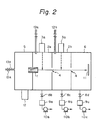
- Fig. 2 shows a modification example of Fig. 1, and a starting-material chamber 5 is provided with a microwave-introducing system 12 and a gas-introducing pipe 13a, and ultra-fine particles are prepared in the starting chamber 5.
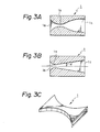
- the nozzle 1 may be a parallel nozzle or a convergent nozzle, but it should preferably a convergent-divergent nozzle as shown in Fig. 3.
- the convergent-divergent nozzle refers to one, which is gradually constricted in opening area from the flow inlet 1a to form a throat portion 1b and again expanded in opening area to become the flow outlet lc.
- the convergent-divergent nozzle can accelerate the flow of the starting material by controlling the pressure ratio P/Po of the pressure P in the reaction chamber 2a to the pressure Po in the starting-material chamber 5 and the ratio A/A * of the opening area A at the flow outlet 1 c to the opening area A * of the throat portion 1b. And, if the pressure ratio P/Po in the starting-material chamber 7 and the reaction chamber 2a is the critical ratio of pressure or less, the outlet flow velocity at the convergent-divergent nozzle becomes the supersonic flow, whereby the starting material can be jetted out at supersonic velocity.
- the critical ratio of pressure refers to the following value. That is, when thellow velocity of the starting material is coincident with the acoustic velocity at the throat portion of the convergent-divergent nozzle, the flow velocity at the flow outlet 1 c coincides ideally with the Mach number which is determined by the opening area ratio A/A * of the cross-sectional area A of the outflow outlet 1c to the cross-sectional area A * of the throat portion A *.
- This relationship is represented specifically by the formula (3) as described below.
- the pressure ratio P/Po of the pressure P in the reaction chamber 2a to the pressure Po in the starting material chamber 5 as determined by the following formula (1) is called critial ratio of pressure.
- y is the specific heat ratio of the flow of the starting material.
- the Mach number M that can be reached by the flow is determined by the pressure Po of the upstream side and the pressure P of the downstream side, according to a following formula: wherein u is the velocity of the fluid, a is the acoustic velocity at the same point, and M exceeds 1 when the ratio P/P o is below the critical ratio of pressure.
- optimum expansion refers to expansion of the starting material flowed when the pressure ratio of the reaction chamber 2a to the starting material chamber 5 is equal to the critical ratio of pressure.
- velocity u of the starting material can be determined by the following formula: wherein To is the gas temperature in the starting-material chamber 7.
- the starting material will proceed straightforward while maintaining substantially the jet-stream cross-section immediately after jetting-out to be converted into a beam.
- the starting material is jetted out into the space in the reaction chambers 2a and 2b, and the collecting chamber 6 with minimum diffusion, independently spatially without interference of these wall surfaces and at a supersonic velocity.
- the "beam” in the present invention means a jet stream flowing with directivity in one direction and with a higher density than that of surrounding space irrespective of the shape of the section of the stream.
- the beam characteristics can be detected by measuring the stream intensity of flying molecules by means of an orifice connected to a differential scanning evacuation system of a mass spectrometer and moving perpendicularly across the beam.
- the output from the mass spectrometer has the maximum value at the center of the beam.
- the output value will decrease gradually with the distance from the center.
- the distance between the center of the beam and the point where the detected value has decreased to half the maximum output is measured.
- the beam diameter is defined as twice the distance measured above.
- the divergence of the beam is evaluated by the divergence angle of the beam defined by the formula below: where d i denotes the beam diameter at a distance 1 1 from the exit of the nozzle to downstream direction,and d 2 at the distance1 2 .
- the desirable 0 value depends on the application field and the size restriction. It is generally not more than ⁇ /6, preferably ⁇ /12, and more preferably ⁇ / 18. With a nozzle of non-circular nozzle section, the divergence angle can be defined correspondingly to the above definition of e .
- the divergence of the beam can be evaluated from the e value by means of a laser doppler velocimeter or photon correlation spectroscopy employing the technology of light-scattering spectroscopy.
- the inside circumferential surface should be substantially in parallel to the center axis at the flow outlet position 1c. This is because the flow direction of the starting material jetted out may be made a parallel flow as easily as possible, since it is influenced by the direction of the inner circumferential surface of the flow outlet 1c.
- the angle of the inner circumferential surface from the throat portion 1b b to the flow outlet 1c relative to the center axis is made 7° or lower, preferably 5° or lower, the flow of the starting material can be maintained substantially uniformly, and therefore in this case, it is not required to be made particularly parallel as described above.
- the convergent-divergent nozzle can be prepared easily.
- the starting material can be jetted out in shape of a slit.
- the rectangular nozzle may be used either in the laterally longer state as shown in the drawing or in the longitudinally longer state.
- the above peel-off phenomenon refers to a phenomenon in which the boundary layer between the inside surface of the convergent-divergent nozzle and the passing fluid becomes greater to make the flow nonuniform, when there is a projection on the inside surface of the convergent-divergent nozzle, etc., which is liable to occur more frequently as the jetted stream is in higher velocity.
- the above-mentioned angle should be made smaller, for prevention of the peel-off phenomenon, for a convergent-divergent nozzle having an inside surface of less finishing precision.
- the inside surface of the convergent-divergent nozzle should be finished to precision preferably of the three reverse triangle marks or more, optimally four marks or more, representing the surface finishing degrees as determined by JIS B 0601.
- the convergent-divergent nozzle can be prepared easily by determining the above finishing precision primarily about the diverged portion.
- the throat portion 1b is required to be made a smoothly curved surface, with the differential coefficient in the change rate of sectional area being not infinite.
- the material for the convergent-divergent nozzle for example, a variety of materials may be employed: metals such as iron, stainless steel etc., and otherwise synthetic resins such as acrylic resin, polyvinyl chloride, polyethylene, polystyrene, polypropylene, etc., ceramic materials, quartz, glass, etc.
- the material may be selected in view of non-reactivity with the starting material, processability, and gas releasability within the vacuum system, etc.
- the inside surface of the convergent-divergent nozzle may be plated or coated with a material which suppresses adhesion or reaction of the starting material on the surface. Specifically, coating with a polyfluoroethylene may be mentioned.
- the length of the convergent-divergent nozzle can be determined as desired depending on the size of the device, etc..
- the heat energy possessed by the starting material is converted to kinetic energy while the material passes through the convergent-divergent nozzle.
- the heat energy may become extremely small, whereby a cooled state can be created.
- the starting material can be also jetted out with the energy thereof being fixed.
- Fig. 4 shows another example of the present invention.
- controlling chambers 14a - 14c having also openings 3. These controlling chambers 14a - 14c are communicated through the valves 8e - 8g and the cleaners 9a - 9c to the pumps 10 - 10c.
- the controlling chamber 14a is provided for controlling easily the pressure ratio before and after the nozzle 1, while the controlling chambers 14b and 14c are provided for preventing mixing of the atmospheres mutually between the reaction chambers 2a and 2b and the collecting chamber 6.
- the controlling chambers 14a and 14b are evacuated more strongly than the reaction chambers 2a and 2b, mixing of these atmospheres can be prevented more reliably.
- the same symbols as in Fig. 1 show the same members.
- the upstream side and the downstream side of the the nozzle in the present invention may be either pressurised, under reduced pressure, closed or open, provided that the pressure control for jetting out the starting material from the nozzle is possible.
- the reaction chambers 2a and 2b are not limited to two compartments, but three or more compartments can be used.
- the following example may be conceivable.
- the energy imparting means 3a and 3b those irradiating photoenergy are used, and no gas is flowed from the gas introducing pipes 12a and 12b.
- an energy necessary for photolysis of disilane is first imparted by excimer laser in the reaction chamber 2a, and then an energy necessary for photolysis of hexafluoroethane with a wavelength-variable laser in the next reaction chamber 2b.
- active species e.g. SiHs
- active species of silicon e.g. CF 3
- active species of carbon e.g. CF 3
- a paraxylylene dimer is pyrolyzed (at about 400 °C) to be converted into a monomer, followed by thermal polymerization (at about 800 ° C) to effect film formation by making avail of the beam characteristic on the substrate 11.
- the Ni ultra-fine particles of the starting material were fed from the starting-material tank 7 into the starting-material chamber 5 with H 2 gas as the carrier gas, and jetted out through the nozzle 1 into the reaction chamber 2a by utilizing the pressure difference.
- a gas mixture of SiH 4 and CH 4 at a ratio of 2:1 was permitted to flow through the gas introducing pipe 12a, and by use of a high pressure mercury lamp as the energy imparting means 3a, the gas mixture of SiH 4 , CH 4 and H 2 in the reaction chamber 2a was excited.
- the Ni ultra-fine particles coated with a film flowed out through the orifice 4 into the reaction chamber 2b.
- Gas flow rates were controlled so that the pressures in the reaction chambers 2a and 2b were equal to each other. Accordingly, mixing through mutual diffusion between the gas mixture comprising SiH 4 and CH 4 and F 2 gas can be suppressed at minimum. Since a microwave (2.45 GHz) was employed as the energy imparting means 3b in the reaction chamber 2b, a plasma of a gas mixture of F 2 and Ne was formed in the reaction chamber 2b. During passage through the reaction chamber 2b, the surface of the Ni ultra-fine particles was fluorinated and impinged onto the substrate in the collecting chamber to be formed into a film.
- the collecting chamber 6 was reduced in pressure to 5 x 10- s Torr or lower to prevent unnecessary adsorption of fluorine gas.
- Ni ultra-fine particles thus subjected to surface treatment had uniform coating on the surface and therefore were not easily oxidized and also, due to little adsorption of moisture, very stable without denaturation for a long term even when left to stand in the air.
- SiC layer could not easily be formed on the Ni ultra-fine particle surfaces, whereby the problems such as readiness in peel-off occurred, and changes with lapse of time in flowability, gas adsorption, etc. were recognized.
- a gas mixture of SiH 4 and H 2 was introduced into the starting-material chamber 5, and a microwave plasma was generated by throwing a microwave of 2.45 GHz from the microwave-introducing system 12 into the starting material chamber 5 to form fine particles of Si under a pressure of 0.1 Torr.
- reaction chamber 2a Into the reaction chamber 2a was introduced a gas mixture of 0 2 gas and Ar gas through the gas introducing pipe 12a, and by use of a microwave introducing system as the energy-imparting means 3a,oxygen plasma was formed in the reaction chamber 2a to form an oxidized coating on the surface of Si ultra-fine particles.
- a microwave introducing system as the energy-imparting means 3a
- a gas mixture of CH 4 and H2 was introduced through the gas introducing system 12b into the reaction chamber 2b and CH 4 plasma was generated in the reaction chamber 2b by throwing microwave from the microwave-introducing system 3b to form a coating of a hydrocarbon on the oxidized coating on the Si fine particles.
- the Si fine particles having a surface layer with a double layer structure thus formed have a constant oxidation degree on the surface, having stable characteristic that no further oxidation will proceed.
- the reaction chamber 2a when only the reaction chamber 2a was used, although the oxidized coating could be formed on the Si fine particles, change with lapse of time after taken out in the air after particle formation was excessive, whereby no constant oxidation degree could be maintained.
- the present invention makes feasible modification or coating of a fine particle surface, or multiple steps of gas phase reactions in a series of systems continuously and efficiently, thus enabling efficient formation of novel fine particles having a new functional characteristics.
Landscapes
- Chemical & Material Sciences (AREA)
- Chemical Kinetics & Catalysis (AREA)
- Organic Chemistry (AREA)
- General Chemical & Material Sciences (AREA)
- Engineering & Computer Science (AREA)
- Materials Engineering (AREA)
- Mechanical Engineering (AREA)
- Metallurgy (AREA)
- Physical Or Chemical Processes And Apparatus (AREA)
- Physical Vapour Deposition (AREA)
- Chemical Vapour Deposition (AREA)
Applications Claiming Priority (2)
| Application Number | Priority Date | Filing Date | Title |
|---|---|---|---|
| JP224929/86 | 1986-09-25 | ||
| JP61224929A JPH074523B2 (ja) | 1986-09-25 | 1986-09-25 | 反応装置 |
Publications (2)
| Publication Number | Publication Date |
|---|---|
| EP0261973A1 true EP0261973A1 (fr) | 1988-03-30 |
| EP0261973B1 EP0261973B1 (fr) | 1991-02-06 |
Family
ID=16821385
Family Applications (1)
| Application Number | Title | Priority Date | Filing Date |
|---|---|---|---|
| EP87308473A Expired EP0261973B1 (fr) | 1986-09-25 | 1987-09-24 | Dispositif et procédé de traitement de particules fines |
Country Status (4)
| Country | Link |
|---|---|
| US (1) | US4991541A (fr) |
| EP (1) | EP0261973B1 (fr) |
| JP (1) | JPH074523B2 (fr) |
| DE (1) | DE3767953D1 (fr) |
Cited By (6)
| Publication number | Priority date | Publication date | Assignee | Title |
|---|---|---|---|---|
| WO1991019016A1 (fr) * | 1990-05-19 | 1991-12-12 | Institut Teoreticheskoi I Prikladnoi Mekhaniki Sibirskogo Otdelenia Akademii Nauk Sssr | Procede et dispositif de revetement |
| EP0642858A3 (fr) * | 1993-09-08 | 1995-11-15 | Ykk Corp | Procédé et appareil pour la préparation de particules composites ultrafines. |
| RU2201472C2 (ru) * | 1998-12-24 | 2003-03-27 | Общество С Ограниченной Ответственностью Обнинский Центр Порошкового Напыления | Способ газодинамического нанесения покрытий и сопловой блок для его осуществления |
| WO2006123965A1 (fr) * | 2005-05-20 | 2006-11-23 | Obschestvo S Ogranichennoi Otvetstvennostiju Obninsky Tsentr Poroshkovogo Napyleniya | Appareil d'application de revetements par dynamique des gaz et procede de revetement |
| EP1715960A4 (fr) * | 2003-11-12 | 2011-05-11 | Intelligent Energy Inc | Procedes permettant de traiter les surfaces de la chambre d'un reacteur generateur d'hydrogene |
| WO2013160874A3 (fr) * | 2012-04-27 | 2014-01-23 | Reactive Metal Particles As | Appareil et procédé permettant de fabriquer des particules |
Families Citing this family (17)
| Publication number | Priority date | Publication date | Assignee | Title |
|---|---|---|---|---|
| JP2524622B2 (ja) * | 1988-07-18 | 1996-08-14 | 真空冶金株式会社 | 超微粒子膜の形成方法 |
| EP0450961B1 (fr) * | 1990-04-05 | 1997-09-10 | Canon Kabushiki Kaisha | Procédé et appareil de fabrication d'un substrat pour cartes optiques |
| US5134963A (en) * | 1991-10-28 | 1992-08-04 | International Business Machines Corporation | LPCVD reactor for high efficiency, high uniformity deposition |
| JP3217905B2 (ja) * | 1992-06-26 | 2001-10-15 | キヤノン株式会社 | 金属酸化物材料及びその製造方法 |
| US5653806A (en) * | 1995-03-10 | 1997-08-05 | Advanced Technology Materials, Inc. | Showerhead-type discharge assembly for delivery of source reagent vapor to a substrate, and CVD process utilizing same |
| US5741363A (en) * | 1996-03-22 | 1998-04-21 | Advanced Technology Materials, Inc. | Interiorly partitioned vapor injector for delivery of source reagent vapor mixtures for chemical vapor deposition |
| US6406745B1 (en) * | 1999-06-07 | 2002-06-18 | Nanosphere, Inc. | Methods for coating particles and particles produced thereby |
| FR2877591B1 (fr) * | 2004-11-09 | 2007-06-08 | Commissariat Energie Atomique | Systeme et procede de production de poudres nanometriques ou sub-micrometriques en flux continu sous l'action d'une pyrolyse laser |
| US20090020411A1 (en) * | 2007-07-20 | 2009-01-22 | Holunga Dean M | Laser pyrolysis with in-flight particle manipulation for powder engineering |
| NL2002590C2 (en) * | 2009-03-04 | 2010-09-07 | Univ Delft Technology | Apparatus and process for atomic or molecular layer deposition onto particles during pneumatic transport. |
| KR101770576B1 (ko) * | 2009-12-04 | 2017-08-23 | 더 리젠츠 오브 더 유니버시티 오브 미시건 | 동축 레이저 보조형 콜드 스프레이 노즐 |
| US10119195B2 (en) | 2009-12-04 | 2018-11-06 | The Regents Of The University Of Michigan | Multichannel cold spray apparatus |
| EP2543443B1 (fr) * | 2010-03-04 | 2019-01-09 | Imagineering, Inc. | Dispositif de formation de revêtement et procédé de production d'une matière de formation de revêtement |
| JP6895162B2 (ja) * | 2017-02-28 | 2021-06-30 | 学校法人 芝浦工業大学 | 超音速フリージェット物理蒸着装置で用いる超音速ノズル、超音速フリージェット物理蒸着装置で用いる超音速ノズルの製造方法、超音速フリージェット物理蒸着装置で用いる超音速ノズルの設計方法及びコンピュータプログラム |
| US20200040444A1 (en) * | 2018-08-02 | 2020-02-06 | Lyten, Inc. | Plasma spray systems and methods |
| US20200263285A1 (en) | 2018-08-02 | 2020-08-20 | Lyten, Inc. | Covetic materials |
| CN111282743B (zh) * | 2020-02-17 | 2021-08-03 | 公主岭市大舜汽车部件有限公司 | 一种汽车生产用喷漆装置 |
Citations (3)
| Publication number | Priority date | Publication date | Assignee | Title |
|---|---|---|---|---|
| EP0006064A1 (fr) * | 1978-05-31 | 1979-12-12 | Saint-Gobain Industries | Dispositif pour la distribution homogène d'un produit pulvérulent à travers une fente longitudinale et applications de ce dispositif |
| CH640887A5 (en) * | 1979-02-19 | 1984-01-31 | Zverev Anatoly | Explosive powder-coating installation |
| EP0189709A1 (fr) * | 1985-01-04 | 1986-08-06 | Saint Gobain Vitrage International | Ejecteur pneumatique de poudre |
Family Cites Families (24)
| Publication number | Priority date | Publication date | Assignee | Title |
|---|---|---|---|---|
| GB955702A (en) * | 1959-08-26 | 1964-04-15 | Ici Ltd | Method of conducting gaseous reactions |
| NL131703C (fr) * | 1960-08-01 | 1900-01-01 | ||
| US3260235A (en) * | 1961-07-25 | 1966-07-12 | Aerojet General Co | Apparatus for coating material with metal |
| US3332870A (en) * | 1962-10-08 | 1967-07-25 | Mhd Res Inc | Method and apparatus for effecting chemical reactions by means of an electric arc |
| LU71343A1 (fr) * | 1974-11-22 | 1976-03-17 | ||
| US4082636A (en) * | 1975-01-13 | 1978-04-04 | Sharp Kabushiki Kaisha | Ion plating method |
| JPS5283084A (en) * | 1975-12-30 | 1977-07-11 | Futaba Denshi Kogyo Kk | Pn junction solid state element and method of producing same |
| JPS53110973A (en) * | 1977-03-10 | 1978-09-28 | Futaba Denshi Kogyo Kk | Method and apparatus for manufacturing compounds |
| CA1148655A (fr) * | 1979-02-23 | 1983-06-21 | Toshinori Takagi | Support d'enregistrement magnetique et methode de fabrication |
| JPS5941510B2 (ja) * | 1979-07-24 | 1984-10-08 | 双葉電子工業株式会社 | 酸化ベリリウム膜とその形成方法 |
| CA1159012A (fr) * | 1980-05-02 | 1983-12-20 | Seitaro Matsuo | Dispositif de deposition de plasma |
| US4682564A (en) * | 1980-11-25 | 1987-07-28 | Cann Gordon L | Magnetoplasmadynamic processor, applications thereof and methods |
| NO803666L (no) * | 1980-12-03 | 1982-06-04 | Moshe Alamaro | Modifisert birkeland/eyde - prosess ii |
| DE3371295D1 (en) * | 1982-03-01 | 1987-06-11 | Toyota Motor Co Ltd | A method and apparatus for making a fine powder compound of a metal and another element |
| JPS58171502A (ja) * | 1982-04-02 | 1983-10-08 | Toyota Motor Corp | セラミック―金属複合微粉末体の製造方法 |
| JPS58171550A (ja) * | 1982-04-02 | 1983-10-08 | Toyota Motor Corp | 粒子分散型複合材料及びその製造方法 |
| US4642227A (en) * | 1982-08-20 | 1987-02-10 | California Institute Of Technology | Reactor for producing large particles of materials from gases |
| JPS59208046A (ja) * | 1983-05-10 | 1984-11-26 | Toyota Motor Corp | 粒子分散型複合材料の製造方法 |
| JPS59208006A (ja) * | 1983-05-10 | 1984-11-26 | Toyota Motor Corp | 合金微粉末の製造方法 |
| JPS59208004A (ja) * | 1983-05-10 | 1984-11-26 | Toyota Motor Corp | 金属微粉末の製造方法 |
| JPS607863A (ja) * | 1983-06-28 | 1985-01-16 | オ−ジ−技研株式会社 | 布中の金属探知器 |
| JPS6018902A (ja) * | 1983-07-13 | 1985-01-31 | Toyota Motor Corp | 磁性流体の製造方法 |
| JPS6051725A (ja) * | 1983-08-31 | 1985-03-23 | Asahi Chem Ind Co Ltd | 焼結成形用粉末及びその製造法 |
| JPS60151273A (ja) * | 1984-01-19 | 1985-08-09 | トヨタ自動車株式会社 | セラミツク被膜付き金属化合物の微粉末の製造方法 |
-
1986
- 1986-09-25 JP JP61224929A patent/JPH074523B2/ja not_active Expired - Lifetime
-
1987
- 1987-09-24 EP EP87308473A patent/EP0261973B1/fr not_active Expired
- 1987-09-24 DE DE8787308473T patent/DE3767953D1/de not_active Expired - Lifetime
-
1989
- 1989-11-30 US US07/443,862 patent/US4991541A/en not_active Expired - Lifetime
Patent Citations (3)
| Publication number | Priority date | Publication date | Assignee | Title |
|---|---|---|---|---|
| EP0006064A1 (fr) * | 1978-05-31 | 1979-12-12 | Saint-Gobain Industries | Dispositif pour la distribution homogène d'un produit pulvérulent à travers une fente longitudinale et applications de ce dispositif |
| CH640887A5 (en) * | 1979-02-19 | 1984-01-31 | Zverev Anatoly | Explosive powder-coating installation |
| EP0189709A1 (fr) * | 1985-01-04 | 1986-08-06 | Saint Gobain Vitrage International | Ejecteur pneumatique de poudre |
Cited By (12)
| Publication number | Priority date | Publication date | Assignee | Title |
|---|---|---|---|---|
| WO1991019016A1 (fr) * | 1990-05-19 | 1991-12-12 | Institut Teoreticheskoi I Prikladnoi Mekhaniki Sibirskogo Otdelenia Akademii Nauk Sssr | Procede et dispositif de revetement |
| EP0642858A3 (fr) * | 1993-09-08 | 1995-11-15 | Ykk Corp | Procédé et appareil pour la préparation de particules composites ultrafines. |
| RU2201472C2 (ru) * | 1998-12-24 | 2003-03-27 | Общество С Ограниченной Ответственностью Обнинский Центр Порошкового Напыления | Способ газодинамического нанесения покрытий и сопловой блок для его осуществления |
| EP1715960A4 (fr) * | 2003-11-12 | 2011-05-11 | Intelligent Energy Inc | Procedes permettant de traiter les surfaces de la chambre d'un reacteur generateur d'hydrogene |
| WO2006123965A1 (fr) * | 2005-05-20 | 2006-11-23 | Obschestvo S Ogranichennoi Otvetstvennostiju Obninsky Tsentr Poroshkovogo Napyleniya | Appareil d'application de revetements par dynamique des gaz et procede de revetement |
| EA011084B1 (ru) * | 2005-05-20 | 2008-12-30 | Общество С Ограниченной Ответственностью Обнинский Центр Порошкового Напыления | Устройство для газодинамического нанесения покрытий и способ нанесения покрытий |
| CN100572584C (zh) * | 2005-05-20 | 2009-12-23 | 有限责任公司奥布宁斯基粉末喷涂中心 | 用于气体动力施加涂层的装置和施加涂层的方法 |
| WO2013160874A3 (fr) * | 2012-04-27 | 2014-01-23 | Reactive Metal Particles As | Appareil et procédé permettant de fabriquer des particules |
| KR20150011366A (ko) * | 2012-04-27 | 2015-01-30 | 리액티브 메탈 파티클스 에이에스 | 입자 제조 장치 및 방법 |
| RU2623935C2 (ru) * | 2012-04-27 | 2017-06-29 | Риэктив Метал Партиклз Ас | Устройство и способ изготовления частиц |
| AU2013254308B2 (en) * | 2012-04-27 | 2017-11-30 | Reactive Metal Particles As | Apparatus and method for manufacturing particles |
| US9833840B2 (en) | 2012-04-27 | 2017-12-05 | Reactive Metal Particles As | Apparatus and method for manufacturing particles |
Also Published As
| Publication number | Publication date |
|---|---|
| EP0261973B1 (fr) | 1991-02-06 |
| US4991541A (en) | 1991-02-12 |
| DE3767953D1 (de) | 1991-03-14 |
| JPS6380843A (ja) | 1988-04-11 |
| JPH074523B2 (ja) | 1995-01-25 |
Similar Documents
| Publication | Publication Date | Title |
|---|---|---|
| US4991541A (en) | Device and process for treating fine particles | |
| US4909914A (en) | Reaction apparatus which introduces one reacting substance within a convergent-divergent nozzle | |
| US4911805A (en) | Apparatus and process for producing a stable beam of fine particles | |
| US4957061A (en) | Plurality of beam producing means disposed in different longitudinal and lateral directions from each other with respect to a substrate | |
| GB2175414A (en) | Controlling density of particles | |
| GB2175709A (en) | Controlling flow of particles | |
| JPS62155934A (ja) | 気相励起装置 | |
| JPS6241409A (ja) | 微粒子流の流れ制御装置 | |
| JPS6242412A (ja) | 気相励起装置 | |
| GB2174509A (en) | Controlling velocity of particles | |
| JPS627431A (ja) | 反応装置 | |
| JPS6242414A (ja) | 気相励起装置 | |
| JPS62115825A (ja) | 微粒子流の流れ制御装置 | |
| JPS61223313A (ja) | 微粒子流の流れ制御装置 | |
| JPS6335779A (ja) | 成膜装置 | |
| JPS61223311A (ja) | 微粒子移送装置 | |
| JPS6242413A (ja) | 気相励起装置 | |
| JPS61218814A (ja) | 微粒子流の流れ制御装置 | |
| JPS61218815A (ja) | 微粒子流の流れ制御装置 | |
| JPS6381821A (ja) | 反応装置 | |
| JPS61220732A (ja) | 微粒子流の流れ制御装置 | |
| JPS61220730A (ja) | 微粒子流の流れ制御装置 | |
| JPS61220768A (ja) | 微粒子流の流れ制御方法 | |
| JPS61218811A (ja) | 微粒子流の流れ制御装置 | |
| JPS6369538A (ja) | 反応装置 |
Legal Events
| Date | Code | Title | Description |
|---|---|---|---|
| PUAI | Public reference made under article 153(3) epc to a published international application that has entered the european phase |
Free format text: ORIGINAL CODE: 0009012 |
|
| AK | Designated contracting states |
Kind code of ref document: A1 Designated state(s): DE FR GB |
|
| 17P | Request for examination filed |
Effective date: 19880823 |
|
| 17Q | First examination report despatched |
Effective date: 19890505 |
|
| 17Q | First examination report despatched |
Effective date: 19891011 |
|
| GRAA | (expected) grant |
Free format text: ORIGINAL CODE: 0009210 |
|
| AK | Designated contracting states |
Kind code of ref document: B1 Designated state(s): DE FR GB |
|
| REF | Corresponds to: |
Ref document number: 3767953 Country of ref document: DE Date of ref document: 19910314 |
|
| ET | Fr: translation filed | ||
| PLBE | No opposition filed within time limit |
Free format text: ORIGINAL CODE: 0009261 |
|
| STAA | Information on the status of an ep patent application or granted ep patent |
Free format text: STATUS: NO OPPOSITION FILED WITHIN TIME LIMIT |
|
| 26N | No opposition filed | ||
| REG | Reference to a national code |
Ref country code: GB Ref legal event code: IF02 |
|
| PGFP | Annual fee paid to national office [announced via postgrant information from national office to epo] |
Ref country code: GB Payment date: 20050912 Year of fee payment: 19 |
|
| PGFP | Annual fee paid to national office [announced via postgrant information from national office to epo] |
Ref country code: FR Payment date: 20050914 Year of fee payment: 19 |
|
| PGFP | Annual fee paid to national office [announced via postgrant information from national office to epo] |
Ref country code: DE Payment date: 20061122 Year of fee payment: 20 |
|
| GBPC | Gb: european patent ceased through non-payment of renewal fee |
Effective date: 20060924 |
|
| REG | Reference to a national code |
Ref country code: FR Ref legal event code: ST Effective date: 20070531 |
|
| PG25 | Lapsed in a contracting state [announced via postgrant information from national office to epo] |
Ref country code: GB Free format text: LAPSE BECAUSE OF NON-PAYMENT OF DUE FEES Effective date: 20060924 |
|
| PG25 | Lapsed in a contracting state [announced via postgrant information from national office to epo] |
Ref country code: FR Free format text: LAPSE BECAUSE OF NON-PAYMENT OF DUE FEES Effective date: 20061002 |