EP0262015A1 - Verfahren zur radiographischen Kontrolle der Schweissnaht eines Rohres auf einer röhrenförmigen Platte und Vorrichtung zur Ausführung des Verfahrens - Google Patents
Verfahren zur radiographischen Kontrolle der Schweissnaht eines Rohres auf einer röhrenförmigen Platte und Vorrichtung zur Ausführung des Verfahrens Download PDFInfo
- Publication number
- EP0262015A1 EP0262015A1 EP87401941A EP87401941A EP0262015A1 EP 0262015 A1 EP0262015 A1 EP 0262015A1 EP 87401941 A EP87401941 A EP 87401941A EP 87401941 A EP87401941 A EP 87401941A EP 0262015 A1 EP0262015 A1 EP 0262015A1
- Authority
- EP
- European Patent Office
- Prior art keywords
- tube
- source
- plate
- introduction
- radiation
- Prior art date
- Legal status (The legal status is an assumption and is not a legal conclusion. Google has not performed a legal analysis and makes no representation as to the accuracy of the status listed.)
- Granted
Links
- 238000000034 method Methods 0.000 title claims abstract description 15
- 238000007689 inspection Methods 0.000 title abstract description 3
- 230000002285 radioactive effect Effects 0.000 claims abstract description 35
- 230000005855 radiation Effects 0.000 claims abstract description 34
- 239000011324 bead Substances 0.000 claims abstract description 12
- 125000006850 spacer group Chemical group 0.000 claims description 7
- 238000002601 radiography Methods 0.000 claims description 6
- 230000006835 compression Effects 0.000 claims description 5
- 238000007906 compression Methods 0.000 claims description 5
- 230000000903 blocking effect Effects 0.000 claims description 4
- 238000012546 transfer Methods 0.000 claims description 4
- 230000000694 effects Effects 0.000 claims description 3
- GKOZUEZYRPOHIO-IGMARMGPSA-N iridium-192 Chemical compound [192Ir] GKOZUEZYRPOHIO-IGMARMGPSA-N 0.000 claims description 3
- 239000012815 thermoplastic material Substances 0.000 claims description 3
- 238000003466 welding Methods 0.000 abstract description 4
- 239000004033 plastic Substances 0.000 abstract description 2
- WABPQHHGFIMREM-UHFFFAOYSA-N lead(0) Chemical compound [Pb] WABPQHHGFIMREM-UHFFFAOYSA-N 0.000 description 4
- 230000007547 defect Effects 0.000 description 3
- 229920001971 elastomer Polymers 0.000 description 3
- 239000000806 elastomer Substances 0.000 description 3
- 238000012360 testing method Methods 0.000 description 2
- 230000001960 triggered effect Effects 0.000 description 2
- 241001479434 Agfa Species 0.000 description 1
- 229910000831 Steel Inorganic materials 0.000 description 1
- 240000008042 Zea mays Species 0.000 description 1
- 238000007664 blowing Methods 0.000 description 1
- 239000011248 coating agent Substances 0.000 description 1
- 239000011247 coating layer Substances 0.000 description 1
- 238000000576 coating method Methods 0.000 description 1
- 238000011161 development Methods 0.000 description 1
- 238000005553 drilling Methods 0.000 description 1
- 239000000839 emulsion Substances 0.000 description 1
- 230000004927 fusion Effects 0.000 description 1
- 239000000463 material Substances 0.000 description 1
- 238000012544 monitoring process Methods 0.000 description 1
- -1 polytetrafluoroethylene Polymers 0.000 description 1
- 229920001343 polytetrafluoroethylene Polymers 0.000 description 1
- 239000004810 polytetrafluoroethylene Substances 0.000 description 1
- 229910000679 solder Inorganic materials 0.000 description 1
- 239000010959 steel Substances 0.000 description 1
- 229920001169 thermoplastic Polymers 0.000 description 1
- 239000004416 thermosoftening plastic Substances 0.000 description 1
Images

Classifications
-
- G—PHYSICS
- G01—MEASURING; TESTING
- G01N—INVESTIGATING OR ANALYSING MATERIALS BY DETERMINING THEIR CHEMICAL OR PHYSICAL PROPERTIES
- G01N23/00—Investigating or analysing materials by the use of wave or particle radiation, e.g. X-rays or neutrons, not covered by groups G01N3/00 – G01N17/00, G01N21/00 or G01N22/00
- G01N23/02—Investigating or analysing materials by the use of wave or particle radiation, e.g. X-rays or neutrons, not covered by groups G01N3/00 – G01N17/00, G01N21/00 or G01N22/00 by transmitting the radiation through the material
- G01N23/06—Investigating or analysing materials by the use of wave or particle radiation, e.g. X-rays or neutrons, not covered by groups G01N3/00 – G01N17/00, G01N21/00 or G01N22/00 by transmitting the radiation through the material and measuring the absorption
- G01N23/18—Investigating the presence of flaws defects or foreign matter
-
- G—PHYSICS
- G01—MEASURING; TESTING
- G01N—INVESTIGATING OR ANALYSING MATERIALS BY DETERMINING THEIR CHEMICAL OR PHYSICAL PROPERTIES
- G01N23/00—Investigating or analysing materials by the use of wave or particle radiation, e.g. X-rays or neutrons, not covered by groups G01N3/00 – G01N17/00, G01N21/00 or G01N22/00
- G01N23/02—Investigating or analysing materials by the use of wave or particle radiation, e.g. X-rays or neutrons, not covered by groups G01N3/00 – G01N17/00, G01N21/00 or G01N22/00 by transmitting the radiation through the material
- G01N23/06—Investigating or analysing materials by the use of wave or particle radiation, e.g. X-rays or neutrons, not covered by groups G01N3/00 – G01N17/00, G01N21/00 or G01N22/00 by transmitting the radiation through the material and measuring the absorption
- G01N23/083—Investigating or analysing materials by the use of wave or particle radiation, e.g. X-rays or neutrons, not covered by groups G01N3/00 – G01N17/00, G01N21/00 or G01N22/00 by transmitting the radiation through the material and measuring the absorption the radiation being X-rays
Definitions
- the present invention relates to a method for radiographic monitoring of the weld bead at the end of a tube on the external face of a tube plate. It also extends to a device for implementing this method.
- the object of the present invention is to provide such a control method which is relatively simple and inexpensive, given the very large number of weld beads between a tubular plate and the tubes passing through it, which provides clear images of these beads. while being safe for operators.
- the source of radioactive radiation is placed at the front end of an introduction and ejection tube, behind a centering tip provided with a locking member in the radiography position, which is slid into the tube of the tube bundle for the introduction, then for the ejection.
- a radially elastic additional centering member is threaded around the introduction and ejection tube so that it is fixed to the inlet of the tube.
- the introduction and ejection tube is integral with a pneumatic cylinder, it comprises at the front of the radioactive radiation source at least one elastic ring, and the elastic ring (s) are compressed in the moment where the source has arrived in the vicinity of the radiography position of the weld bead by operating the piston of the jack. - It ensures the compression of the elastic ring (s) by triggering the pneumatic cylinder requesting a rod secured to the piston of the cylinder in the direction of withdrawal of the tube from the tube bundle.
- the elastic guide means consist of an end piece with elastic branches.
- the device then preferably further comprises a radially elastic cylindrical centralizer, with an external diameter slightly greater than the internal diameter of the tube welded to the tube plate, in the state of compression.
- the tube for introducing and ejecting the source of radioactive radiation is secured to a pneumatic cylinder, and its front end is formed by a spacer provided with at least one radially expandable ring.
- the piston of the pneumatic cylinder is then preferably provided with a rod sliding in the spacer and integral with a nozzle adjacent to the ring and capable of compressing the latter, and it is arranged in the cylinder so as to be pushed back by report to the X-ray film when establishing the pressure in the cylinder.
- the source of radioactive radiation advantageously consists of iridium 192 or yterbium 169.
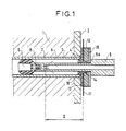
- the tubular plate 1 is provided with a coating layer 2.
- the tube 3 of the tubular bundle is welded to the tubular plate at its coating by the circumferential weld 4, the compactness of which is to be checked.
- an elongated source holder tube 5, pierced with a blind bore 6, is introduced into the tube 3, at the bottom of which is placed the radioactive source 7, either of iridium 192 or of yterbium 169, very small dimensions, for example 3mm x 2mm or 2.5mm x 2.5mm or even 1mm x 1mm or 1mm x 0.5mm.
- This source must be of activity of less than 300 becquerels, and for example of 200 becquerels, in order to maintain a ratio of exposure time / transfer time in position of the source greater than 20.
- a lead screen 15 of thickness at least equal to 5mm reduces the influence of the transfer of the source in its operating position on the impression of the film by radiation and protects the operator.
- the film 11 on which the image of the weld is to be recorded is a double film, each of the sheets of which is a very slow and fine-grained film, of the type marketed by the Kodak companies under the designation R or Agfa under the designation D2 . These films are sandwiched between three very thin lead screens (about 0.05 mm), of the "X-ray" type. This enhances the image quality and increases the exposure time, which must be at least 30 seconds.
- the thin lead screens arranged on either side of the films and between them are intended to enhance the contrast of the film by producing secondary electronic radiation. These screens are not coated with paper to minimize their thickness.
- All the lead films and screens are contained in a rectangular heat-sealed plastic envelope impervious to daylight, but permeable to radioactive radiation, such as polytetrafluoroethylene, composed of two recessed washers, one 12 opposite the tube plate, and the other 13 facing the side of that -this.
- This envelope is pierced with a non-heat sealed central hole, the washer 13 on the side of the tubular plate coming to cover by its annular rim 14 the edges of this central hole. Because the central hole is not heat sealed, and the washers are used, the drilling diameter of the film can be reduced in order to interpret the entire weld bead.
- the source-carrying tube 5 comprises a central blind bore 6 at the bottom of which the radioactive source 7 is introduced at the time of its use, and a shoulder 5A. Its end is provided with a thread 8 into which a support bolt for an end guide 9 of the elastomer tube is screwed, with three branches which come to bear on the periphery of the heat exchange tube and maintain the source in a determined position relative to the weld to be checked. Furthermore, an elastomer centering ring 10, threaded around the source-carrying tube so as not to project onto the areas of the weld to be examined, makes it possible to improve the positioning of the film with respect to the weld.
- the radiographic inspection of the weld is carried out as follows.
- the radioactive source is introduced at the bottom of the source-carrying tube, then quickly pushes the latter into the exchanger tube until its shoulder 5A abuts against the screen of lead 15, the position of this shoulder being such that the source is at a very precise distance D from the film and sees the solder at an angle ensuring a clear radiography.
- the end guide 9 of the tube maintains the source in a fixed position.
- the source is then allowed to irradiate the weld during the chosen exposure time, which we have seen that it must be at least 20 times greater than the transfer time from the source to the position. This time will in practice be determined by a series of tests so as to obtain densities on the film in double film of 1.8 to 3.5 (areas furthest from the center of the film) or in single film of 1 to 1. , 7.
- Then we quickly remove the source tube.
- the cartridge containing the radiographic film is removed and the latter developed.
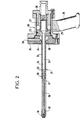
- the pneumatic cylinder for positioning the radioactive source in FIG. 2 comprises a cylinder body 20 and a source-carrying tube 21 with a guide spacer.
- the cylinder body 20 contains a piston 22 movable in a cylindrical cavity 23.
- a cavity 24 formed in the center of the front face 25 of the cylinder housing can be connected to an air source compressed by conduit 26.
- the piston 22 is kept at rest in the advanced position by the helical spring 27, bearing on a stop 28.
- a handle 29 allows the positioning of the source-carrying tube in the heat exchange tube, the welding of which on the tube plate is to be checked.
- a circular lead plate 30 ensures the blocking of the cylinder against the tubular plate and biological protection.
- the source-carrying tube 21 consists of a fixed external tube 31, integral with the front face 25 of the cylinder housing, and an internal tube 32 movable inside the previous one, and pierced with a bore 33 of which the front end 34 serves as a housing for the radioactive source.
- the outer tube 31 is extended by a guide spacer 36, pierced with a bore in which the piston rod 37 can slide.
- the latter ends at its front end with a screwed end 38.
- the guide spacer 36 is provided with two elastomer washers, one 39 near the bottom of its bore in which the internal tube slides, and the other 40 at its front end, behind end piece 38.
- the operation of the actuator for placing the radioactive source is as follows.
- the source 7 is introduced at the bottom 34 of the bore 33 of the internal tube 32, then the fixed external tube 31 is quickly penetrated into the exchanger tube, the weld of which is to be checked until the blocking plate 30 comes into contact with the face of the tube plate.
- the external tube 31 having arrived in position, the actuator is triggered.
- the air pressure arriving through the conduit 26 pushes the piston 22 backwards, and consequently the internal tube 32 integral with the latter, which recedes with its piston rod 37 as shown by the arrow in FIG. 3.
- the elastic rings 39 and 40, in contact with the internal wall of the exchanger tube are compressed, swell and block the internal tube 32, and consequently the radioactive source 7, in a well-defined position at the distance D from the film. behind the weld to be checked.
- the source is then left in the active position for the desired exposure time.
- the cylinder is triggered in the opposite direction. Since the pressure no longer exerts on the front face of the piston, the spring 27 pushes the piston and the inner tube forward.
- the elastic rings 39 and 40 come off from the wall of the exchanger tube.
- the outer tube is then quickly removed from the inside of the exchanger tube. Then the envelope containing the radiographic film is removed and the development thereof is carried out.
Landscapes
- Health & Medical Sciences (AREA)
- Biochemistry (AREA)
- Physics & Mathematics (AREA)
- Life Sciences & Earth Sciences (AREA)
- Chemical & Material Sciences (AREA)
- Analytical Chemistry (AREA)
- General Health & Medical Sciences (AREA)
- General Physics & Mathematics (AREA)
- Immunology (AREA)
- Pathology (AREA)
- Toxicology (AREA)
- Analysing Materials By The Use Of Radiation (AREA)
- Butt Welding And Welding Of Specific Article (AREA)
Priority Applications (1)
| Application Number | Priority Date | Filing Date | Title |
|---|---|---|---|
| AT87401941T ATE69885T1 (de) | 1986-09-01 | 1987-08-28 | Verfahren zur radiographischen kontrolle der schweissnaht eines rohres auf einer roehrenfoermigen platte und vorrichtung zur ausfuehrung des verfahrens. |
Applications Claiming Priority (2)
| Application Number | Priority Date | Filing Date | Title |
|---|---|---|---|
| FR8612282A FR2603380B1 (fr) | 1986-09-01 | 1986-09-01 | Procede de controle radiographique de la soudure d'un tube sur une plaque tubulaire, et dispositif de mise en oeuvre de ce procede |
| FR8612282 | 1986-09-01 |
Publications (2)
| Publication Number | Publication Date |
|---|---|
| EP0262015A1 true EP0262015A1 (de) | 1988-03-30 |
| EP0262015B1 EP0262015B1 (de) | 1991-11-27 |
Family
ID=9338609
Family Applications (1)
| Application Number | Title | Priority Date | Filing Date |
|---|---|---|---|
| EP87401941A Expired - Lifetime EP0262015B1 (de) | 1986-09-01 | 1987-08-28 | Verfahren zur radiographischen Kontrolle der Schweissnaht eines Rohres auf einer röhrenförmigen Platte und Vorrichtung zur Ausführung des Verfahrens |
Country Status (4)
| Country | Link |
|---|---|
| EP (1) | EP0262015B1 (de) |
| AT (1) | ATE69885T1 (de) |
| DE (1) | DE3774817D1 (de) |
| FR (1) | FR2603380B1 (de) |
Cited By (5)
| Publication number | Priority date | Publication date | Assignee | Title |
|---|---|---|---|---|
| FR2669731A1 (fr) * | 1990-11-22 | 1992-05-29 | Framatome Sa | Dispositif de radiographie d'un cordon de soudure. |
| WO1994024546A1 (fr) * | 1993-03-18 | 1994-10-27 | 'energomontage-International', Joint Venture | Detecteur de defauts gamma utilisant du selenium 75 comme source et procede de production de ladite source |
| CN113714667A (zh) * | 2021-08-17 | 2021-11-30 | 沈阳东方钛业股份有限公司 | 一种管板堆焊变形的预防及处理方法 |
| CN116879323A (zh) * | 2023-07-11 | 2023-10-13 | 深圳市中昌检测技术有限公司 | 一种环焊缝射线成型检测装置 |
| CN119831985A (zh) * | 2025-03-14 | 2025-04-15 | 宝鸡市汇鑫金属复合材料有限公司 | 基于x光图像的复合板材爆炸焊缺陷检测方法 |
Families Citing this family (1)
| Publication number | Priority date | Publication date | Assignee | Title |
|---|---|---|---|---|
| CN106584877B (zh) * | 2016-12-09 | 2023-05-30 | 重庆寅悦恒工贸有限公司 | 车用管件定心机构 |
Citations (4)
| Publication number | Priority date | Publication date | Assignee | Title |
|---|---|---|---|---|
| US3254224A (en) * | 1962-07-18 | 1966-05-31 | Halcon International Inc | Apparatus for moving a radioactive source between exposure and safe positions |
| FR2011646A1 (en) * | 1968-06-25 | 1970-03-06 | Atomic Energy Authority Uk | Radiographic weld testing for tube to plate welds |
| GB1272404A (en) * | 1968-10-16 | 1972-04-26 | Atomic Energy Authority Uk | Improvements in or relating to the radiography of welds |
| GB2109660A (en) * | 1981-11-07 | 1983-06-02 | Northern Eng Ind | Radiographic examination apparatus |
Family Cites Families (2)
| Publication number | Priority date | Publication date | Assignee | Title |
|---|---|---|---|---|
| JPS5520490A (en) * | 1979-07-07 | 1980-02-13 | Kubota Ltd | Radiation transmission photographing unit |
| JPS5669540A (en) * | 1979-11-12 | 1981-06-10 | Hitachi Ltd | Inspecting device of radiation transmission |
-
1986
- 1986-09-01 FR FR8612282A patent/FR2603380B1/fr not_active Expired
-
1987
- 1987-08-28 DE DE8787401941T patent/DE3774817D1/de not_active Expired - Fee Related
- 1987-08-28 EP EP87401941A patent/EP0262015B1/de not_active Expired - Lifetime
- 1987-08-28 AT AT87401941T patent/ATE69885T1/de active
Patent Citations (4)
| Publication number | Priority date | Publication date | Assignee | Title |
|---|---|---|---|---|
| US3254224A (en) * | 1962-07-18 | 1966-05-31 | Halcon International Inc | Apparatus for moving a radioactive source between exposure and safe positions |
| FR2011646A1 (en) * | 1968-06-25 | 1970-03-06 | Atomic Energy Authority Uk | Radiographic weld testing for tube to plate welds |
| GB1272404A (en) * | 1968-10-16 | 1972-04-26 | Atomic Energy Authority Uk | Improvements in or relating to the radiography of welds |
| GB2109660A (en) * | 1981-11-07 | 1983-06-02 | Northern Eng Ind | Radiographic examination apparatus |
Non-Patent Citations (2)
| Title |
|---|
| PATENT ABSTRACTS OF JAPAN, vol. 4, no. 51, 17 avril 1980, page 17 P 7; & JP-A-55 20 490 (KUBOTA TEKKO K.K.) 13-02-1980 * |
| PATENT ABSTRACTS OF JAPAN, vol. 5, no. 130 (P-76)[802], 20 août 1981; & JP-A-56 69 540 (HITACHI SEISAKUSHO K.K.) 10-06-1981 * |
Cited By (5)
| Publication number | Priority date | Publication date | Assignee | Title |
|---|---|---|---|---|
| FR2669731A1 (fr) * | 1990-11-22 | 1992-05-29 | Framatome Sa | Dispositif de radiographie d'un cordon de soudure. |
| WO1994024546A1 (fr) * | 1993-03-18 | 1994-10-27 | 'energomontage-International', Joint Venture | Detecteur de defauts gamma utilisant du selenium 75 comme source et procede de production de ladite source |
| CN113714667A (zh) * | 2021-08-17 | 2021-11-30 | 沈阳东方钛业股份有限公司 | 一种管板堆焊变形的预防及处理方法 |
| CN116879323A (zh) * | 2023-07-11 | 2023-10-13 | 深圳市中昌检测技术有限公司 | 一种环焊缝射线成型检测装置 |
| CN119831985A (zh) * | 2025-03-14 | 2025-04-15 | 宝鸡市汇鑫金属复合材料有限公司 | 基于x光图像的复合板材爆炸焊缺陷检测方法 |
Also Published As
| Publication number | Publication date |
|---|---|
| DE3774817D1 (de) | 1992-01-09 |
| EP0262015B1 (de) | 1991-11-27 |
| FR2603380B1 (fr) | 1988-11-10 |
| FR2603380A1 (fr) | 1988-03-04 |
| ATE69885T1 (de) | 1991-12-15 |
Similar Documents
| Publication | Publication Date | Title |
|---|---|---|
| EP0473489A1 (de) | Verfahren zur Kontrolle des Aufsetzens eines transportierbaren Elements and Kontrolle der Verbindungsdichtheit mit einer festen Struktur und Anwendung dieses Verfahrens | |
| BE1013199A3 (fr) | Conteneur pour renfermer separement deux substances differentes. | |
| EP0448894B1 (de) | Verfahren und Einrichtung zur Kontrolle der Verbindung einer bienennestartigen Struktur auf einem Träger | |
| EP0262015B1 (de) | Verfahren zur radiographischen Kontrolle der Schweissnaht eines Rohres auf einer röhrenförmigen Platte und Vorrichtung zur Ausführung des Verfahrens | |
| FR2638238A1 (fr) | Detecteur pour le radiocarottage avec une interface optique de decouplage | |
| FR2988205A1 (fr) | Dispositif de montage etanche d'un organe interchangeable sur une enceinte de confinement a securite renforcee | |
| EP1336059B1 (de) | Ventil mit abgedichtetem balg und verpackungskasten für giftige fluide transportierende behälter | |
| FR2717587A1 (fr) | Dispositif de localisation en temps réel de sources de rayonnement. | |
| CA1300693C (fr) | Procede de fixation par soudage d'une tubulure sur un element de paroi deforte epaisseur | |
| FR2550476A1 (fr) | Appareil pour elargir des tubes ou des manchons places dans des tubes | |
| EP2100309B1 (de) | Einrichtung zum transfer von kernbrennstoffkassetten zwischen einem transportbehälter und einer lagereinrichtung | |
| EP0312460B1 (de) | Vorrichtung zur entkuppelbaren Verbindung zweier dichter Hohlräume | |
| EP1116242A1 (de) | Verfahren und anlage zum füllen von fässern mit gefährlichem abfall | |
| WO2001061707A1 (fr) | Procede de controle d'une operation de fermeture etanche par soudage de l'extremite d'un canal de remplissage traversant le bouchon superieur d'un crayon de combustible nucleaire | |
| EP4570458A1 (de) | Vorrichtung zur handhabung von in einem handschuhfach enthaltenen elementen, die eine abgedichtete doppelwand bilden, handschuhkasten dafür. | |
| FR2734078A1 (fr) | Procede d'installation d'une traversee etanche dans le mur d'une cellule | |
| FR2493268A1 (fr) | Procede d'emballage de produits dans des recipients thermo-soudables | |
| EP0428433A1 (de) | Vorrichtung zum Fixieren der Steuerstabsführungsplatte im Kernreaktordruckgefäss | |
| FR3033077A1 (fr) | Dispositif de transfert entre un conteneur et une cellule et procede de mise en oeuvre | |
| EP0311475B1 (de) | Vorrichtung zum Dichtigkeitsprüfen von Behältern für Fluide unter Druck | |
| EP0027218A1 (de) | Gekühlte Kassette für gammagraphischen Film | |
| FR2871213A1 (fr) | Dispositif de fermeture et de confinement d'une enceinte | |
| FR2649824A1 (fr) | Emballage d'entreposage et de transport de matieres fissiles | |
| EP0479344B1 (de) | Arbeitssystem für Innenwände der Wasserkammern in dem Dampferzeuger eines Kernreaktors | |
| FR2691387A1 (fr) | Appareil de remise en forme de pièces tubulaires. |
Legal Events
| Date | Code | Title | Description |
|---|---|---|---|
| PUAI | Public reference made under article 153(3) epc to a published international application that has entered the european phase |
Free format text: ORIGINAL CODE: 0009012 |
|
| AK | Designated contracting states |
Kind code of ref document: A1 Designated state(s): AT BE DE FR GB IT |
|
| 17P | Request for examination filed |
Effective date: 19880929 |
|
| 17Q | First examination report despatched |
Effective date: 19900807 |
|
| GRAA | (expected) grant |
Free format text: ORIGINAL CODE: 0009210 |
|
| AK | Designated contracting states |
Kind code of ref document: B1 Designated state(s): AT BE DE FR GB IT |
|
| REF | Corresponds to: |
Ref document number: 69885 Country of ref document: AT Date of ref document: 19911215 Kind code of ref document: T |
|
| GBT | Gb: translation of ep patent filed (gb section 77(6)(a)/1977) | ||
| REF | Corresponds to: |
Ref document number: 3774817 Country of ref document: DE Date of ref document: 19920109 |
|
| ITF | It: translation for a ep patent filed | ||
| PGFP | Annual fee paid to national office [announced via postgrant information from national office to epo] |
Ref country code: FR Payment date: 19920527 Year of fee payment: 6 |
|
| PGFP | Annual fee paid to national office [announced via postgrant information from national office to epo] |
Ref country code: DE Payment date: 19920615 Year of fee payment: 6 Ref country code: BE Payment date: 19920615 Year of fee payment: 6 |
|
| PGFP | Annual fee paid to national office [announced via postgrant information from national office to epo] |
Ref country code: GB Payment date: 19920625 Year of fee payment: 6 |
|
| PGFP | Annual fee paid to national office [announced via postgrant information from national office to epo] |
Ref country code: AT Payment date: 19920831 Year of fee payment: 6 |
|
| PLBE | No opposition filed within time limit |
Free format text: ORIGINAL CODE: 0009261 |
|
| STAA | Information on the status of an ep patent application or granted ep patent |
Free format text: STATUS: NO OPPOSITION FILED WITHIN TIME LIMIT |
|
| 26N | No opposition filed | ||
| PG25 | Lapsed in a contracting state [announced via postgrant information from national office to epo] |
Ref country code: GB Effective date: 19930828 Ref country code: AT Effective date: 19930828 |
|
| PG25 | Lapsed in a contracting state [announced via postgrant information from national office to epo] |
Ref country code: BE Effective date: 19930831 |
|
| BERE | Be: lapsed |
Owner name: STEIN INDUSTRIE Effective date: 19930831 |
|
| GBPC | Gb: european patent ceased through non-payment of renewal fee |
Effective date: 19930828 |
|
| PG25 | Lapsed in a contracting state [announced via postgrant information from national office to epo] |
Ref country code: FR Effective date: 19940429 |
|
| PG25 | Lapsed in a contracting state [announced via postgrant information from national office to epo] |
Ref country code: DE Effective date: 19940503 |
|
| REG | Reference to a national code |
Ref country code: FR Ref legal event code: ST |
|
| PG25 | Lapsed in a contracting state [announced via postgrant information from national office to epo] |
Ref country code: IT Free format text: LAPSE BECAUSE OF NON-PAYMENT OF DUE FEES;WARNING: LAPSES OF ITALIAN PATENTS WITH EFFECTIVE DATE BEFORE 2007 MAY HAVE OCCURRED AT ANY TIME BEFORE 2007. THE CORRECT EFFECTIVE DATE MAY BE DIFFERENT FROM THE ONE RECORDED. Effective date: 20050828 |