EP0262026A1 - Vorrichtung zur Oberflächenentstaubung - Google Patents
Vorrichtung zur Oberflächenentstaubung Download PDFInfo
- Publication number
- EP0262026A1 EP0262026A1 EP87402041A EP87402041A EP0262026A1 EP 0262026 A1 EP0262026 A1 EP 0262026A1 EP 87402041 A EP87402041 A EP 87402041A EP 87402041 A EP87402041 A EP 87402041A EP 0262026 A1 EP0262026 A1 EP 0262026A1
- Authority
- EP
- European Patent Office
- Prior art keywords
- face
- pad
- dust
- blind holes
- vis
- Prior art date
- Legal status (The legal status is an assumption and is not a legal conclusion. Google has not performed a legal analysis and makes no representation as to the accuracy of the status listed.)
- Withdrawn
Links
- 238000010410 dusting Methods 0.000 title claims abstract description 4
- 239000000428 dust Substances 0.000 claims abstract description 36
- 239000000463 material Substances 0.000 claims abstract description 14
- 239000004753 textile Substances 0.000 claims abstract description 11
- 239000000835 fiber Substances 0.000 claims description 6
- 210000002268 wool Anatomy 0.000 claims description 5
- 230000004520 agglutination Effects 0.000 claims description 2
- 230000005012 migration Effects 0.000 claims description 2
- 238000013508 migration Methods 0.000 claims description 2
- 239000000470 constituent Substances 0.000 claims 1
- 238000010521 absorption reaction Methods 0.000 abstract description 5
- 239000004744 fabric Substances 0.000 description 13
- 230000000694 effects Effects 0.000 description 6
- 238000004078 waterproofing Methods 0.000 description 5
- 238000005086 pumping Methods 0.000 description 4
- 230000008901 benefit Effects 0.000 description 3
- 239000004743 Polypropylene Substances 0.000 description 2
- 238000004026 adhesive bonding Methods 0.000 description 2
- 239000011230 binding agent Substances 0.000 description 2
- 238000000151 deposition Methods 0.000 description 2
- 238000005304 joining Methods 0.000 description 2
- 230000014759 maintenance of location Effects 0.000 description 2
- 239000000203 mixture Substances 0.000 description 2
- 230000035515 penetration Effects 0.000 description 2
- -1 polypropylene Polymers 0.000 description 2
- 229920001155 polypropylene Polymers 0.000 description 2
- 238000004381 surface treatment Methods 0.000 description 2
- 239000012209 synthetic fiber Substances 0.000 description 2
- 229920002994 synthetic fiber Polymers 0.000 description 2
- 238000009825 accumulation Methods 0.000 description 1
- 230000004523 agglutinating effect Effects 0.000 description 1
- 238000009960 carding Methods 0.000 description 1
- 230000000295 complement effect Effects 0.000 description 1
- 230000008021 deposition Effects 0.000 description 1
- 238000009826 distribution Methods 0.000 description 1
- 230000035699 permeability Effects 0.000 description 1
- 239000002861 polymer material Substances 0.000 description 1
- 239000004800 polyvinyl chloride Substances 0.000 description 1
- 229920000915 polyvinyl chloride Polymers 0.000 description 1
- 238000003825 pressing Methods 0.000 description 1
- 229920006395 saturated elastomer Polymers 0.000 description 1
- 238000009738 saturating Methods 0.000 description 1
- 229920001169 thermoplastic Polymers 0.000 description 1
Images
Classifications
-
- A—HUMAN NECESSITIES
- A47—FURNITURE; DOMESTIC ARTICLES OR APPLIANCES; COFFEE MILLS; SPICE MILLS; SUCTION CLEANERS IN GENERAL
- A47L—DOMESTIC WASHING OR CLEANING; SUCTION CLEANERS IN GENERAL
- A47L13/00—Implements for cleaning floors, carpets, furniture, walls, or wall coverings
- A47L13/10—Scrubbing; Scouring; Cleaning; Polishing
- A47L13/16—Cloths; Pads; Sponges
Definitions
- the present invention relates to a surface dusting device, in particular intended to replace the traditional dust cloth.
- the cloth which can be used on both sides, possibly in the folded state, is messy for its user and for its environment, unless binding precautions are taken.
- a surface dedusting device which may include, in one of its embodiments, a flexible, elastically compressible pad, of a needle-punched breathable textile material, said pad being flat so as to have first and second faces approximately parallel, of dimensions much greater than their relative spacing, said first face being waterproofed at least vis-à-vis dust and said second face being permeable with respect to air and dust; this second face is covered with a fabric whose presence and nature are characteristic of this known device; more specifically, this fabric is made of fibers of a thermoplastic polymer material selected for its tribo-electrostatic properties, in order to have an aptitude for retaining the dust which it collects on the surface to be dusted, with which the device is placed contact through this fabric.
- the fabric characteristic of the known product prevents this dust from migrating towards the pad of needled textile material which, thereby , contributes little to the retention of dust by the device; in fact, most of the dust remains on the surface, i.e. on the fabric, which is quickly saturated and must be cleaned frequently to prevent the accumulated dust from settling on the surface again to dust.
- the known device offers practically no advantages in comparison with the traditional dust cloth.
- the object of the present invention is to remedy these drawbacks.
- the surface dedusting device comprising a flexible, elastically compressible pad, of a needle-punched, breathable stextile material, said pad being flat so as to have approximately first and second faces. parallels of dimensions much greater than their relative spacing, said first face being waterproofed at least with respect to dust and said second face being permeable with respect to air and dust, is characterized in that said second face is free and capable of coming into direct contact with a surface to be dusted to allow direct migration of dust from said surface towards the inside of the pad.
- the first side thus waterproofed of the pad can advantageously be used for gripping the device, which is applied by the second side of the pad to the surfaces to be dusted, which prevents the user from getting dirty;
- the direct contact of the second face of the pad with the surface to be dusted and the waterproofing of the first face of the pad against dust and preferably vis-à-vis the air also make it possible to transform the movement natural wiping, accompanied by alternating pressures and detents applied to the device, in effect of pumping the dust inside the tampon where this dust is fixed, which makes it possible to retain comparatively large amounts of dust inside the tampon, for a comparatively small area of its second face; thus, in a more discreet aspect than that of the traditional dust cloth and while being simpler and less expensive than the device described by the aforementioned American patent, the device according to the invention offers interesting characteristics of dust retention by absorption. .
- blind holes are drilled in the second face of the tampon, for example approximately perpendicular to this second face, which blind holes can extend in the immediate vicinity of the first face of the pad, without however reaching this first face, or interrupting the thickness of the pad; such a structure makes it possible both to accentuate the aforementioned pumping effect and to considerably facilitate the access of dust to the interior of the tampon, which results in a significant increase in the absorption capacities of the latter.
- absorption capacities can be influenced by judiciously choosing the dimensions and the relative position of the holes, as well as by judiciously choosing the density and the composition of the needle punched textile material; advantageously, this textile material contains from 20 to 50% of wool fibers, and the complement of synthetic fibers to benefit from the known capacities of absorption of wool.
- the waterproofing of the first face of the tampon can be ensured by any appropriate means, retaining flexibility on this face or, preferably, stiffening it both to facilitate gripping of the device and to allow distribution throughout the tampon , of said alternating pressures and detents which are generally applied more or less regularly to the first face thereof during use of the device, and thus make said pumping effect appear in the entire buffer to make a maximum of the volume of the buffer participate in the aforementioned pumping effect even if one acts only locally on the first face of it.
- this for example, it is possible to provide for this purpose agglutination of the textile material of the tampon at the level of the first face thereof thanks to the localized addition of a binder, or to any other surface treatment; it is also possible to provide for the deposition and fixing, for example by gluing, of a sheet of waterproofing material against the first face of the pad, this sheet preferably being rigid but also being able to be flexible.
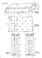
- the resiliently compressible flexible pad of needled air-permeable textile material intended to come into contact with the surfaces to be dusted;
- this pad advantageously made from a textile web with a filamentary structure, obtained by needling or carding frayed fabric preferably with a majority of wool fibers, for example based on 60% wool and 40% various synthetic fibers , has a flat shape; this shape is defined by two approximately planar faces 2, 3, approximately mutually parallel, connected by a song 4; the two faces 2 and 3, rectangular in the nonlimiting example illustrated, have dimensions in plane L and 1 much greater than their relative spacing, or thickness e of the pad.
- the face 3 is intended to be turned towards the hand of use; at this face 3, the pad 1 is waterproofed against dust either by a surface treatment agglutinating the textile fibers in the immediate vicinity of the face 3, over a preferably minimal portion of the thickness e of the pad , for example by means of a binder deposited on the face 3, in a manner not illustrated, either by depositing and fixing on this face 3 a sheet 5 of impermeable material in particular with respect to dust and preferably also vis-à-vis the air, as illustrated; this sheet 5 can be flexible, for example polyvinyl chloride; preferably, this sheet is rigid, and for example constituted by a rigid sheet of polypropylene; this sheet preferably covers the entire face 3 of the pad 1, with which it is joined for example by gluing, preferably continuously or, at least, uniformly distributed over the whole of the face 3, optionally by means of a layer not shown of a material known to a person skilled in the art to
- the face 2 of the pad remains free to come into direct contact with the surfaces to be cleaned, and has characteristics preserved in permeability to air and to dust.
- blind holes 6 arranged in the buffer 1 open into the face 2 thereof, preferably in a regularly distributed manner and for example in a staggered arrangement as shown in the figure 2;
- FIGS. 3 and 4 respectively illustrate two embodiments of these terminal holes, designated respectively by the references 6a and 6b, it being understood that these two embodiments can be found on the same pad 1;
- the blind hole 6a opens not only in the face 2 of the pad 1, but also in the face 3 of the latter at the level of which it is closed, in a manner impermeable to dust and preferably air, in practice by the sheet 5 attached to this face 3 in this non-limiting example; in the case of the embodiment illustrated in FIG.
- the blind hole 6b is interrupted in the mass of the pad 1, between the faces 2 and 3 of the latter but preferably closer to the face 3 than to the face 2; in both cases, the blind hole has an approximately cylindrical shape of revolution around an axis 7a or 7b respectively, approximately perpendicular to the face 2 of the pad 1; naturally, different shapes could be adopted for the holes blind 6a, 6b, but note that the shapes illustrated in Figures 3 and 4 are particularly easy to achieve.
- blind holes 6, 6a, 6b considerably facilitates the penetration of dust inside the pad 1; however, this penetration is also possible, although to a lesser extent, in the absence of such blind holes 6, 6a, 6b.
- buffer 1 - dimensions: 1 x L: from 6 x 8cm2 to 20 x 30cm2, and in particular from 7 x 12.5 cm2 to 10 x 15cm2; - density: from 600 g / m2 to 2800 g / m2, and for example of the order of 1600 g / m2, with a thickness of between 1.5 and 3 cm, and for example of the order of 2 cm; - waterproofing thickness (thickness of sheet 5 in the example illustrated) of the order of 0.5 mm to 2 mm; - relative spacing D between the centers of the blind holes 6, 6a, 6b at the level of the face 2: from 4mm to 50mm, and for example of the order of 1.3 cm to 2 cm; - dimension of the holes at the level of face 2 or in section through any plane parallel to this face 2: inscribed circle with a diameter d of between 1 mm and 12 mm, and for example diameter of the order of 3 to 4
Landscapes
- Treatment Of Fiber Materials (AREA)
- Absorbent Articles And Supports Therefor (AREA)
Applications Claiming Priority (2)
| Application Number | Priority Date | Filing Date | Title |
|---|---|---|---|
| FR8612861 | 1986-09-15 | ||
| FR8612861A FR2603793B1 (fr) | 1986-09-15 | 1986-09-15 | Dispositif de depoussierage de surface |
Publications (1)
| Publication Number | Publication Date |
|---|---|
| EP0262026A1 true EP0262026A1 (de) | 1988-03-30 |
Family
ID=9338940
Family Applications (1)
| Application Number | Title | Priority Date | Filing Date |
|---|---|---|---|
| EP87402041A Withdrawn EP0262026A1 (de) | 1986-09-15 | 1987-09-14 | Vorrichtung zur Oberflächenentstaubung |
Country Status (2)
| Country | Link |
|---|---|
| EP (1) | EP0262026A1 (de) |
| FR (1) | FR2603793B1 (de) |
Cited By (3)
| Publication number | Priority date | Publication date | Assignee | Title |
|---|---|---|---|---|
| FR2635050A1 (fr) * | 1988-08-02 | 1990-02-09 | Zulick Tadeck | Cartouche de transmission ou de recuperation |
| EP0829222A1 (de) * | 1996-09-13 | 1998-03-18 | Minnesota Mining And Manufacturing Company | Materialbahn mit Klebrigmacher |
| US6746974B1 (en) | 1999-03-10 | 2004-06-08 | 3M Innovative Properties Company | Web material comprising a tackifier |
Citations (5)
| Publication number | Priority date | Publication date | Assignee | Title |
|---|---|---|---|---|
| US3144671A (en) * | 1958-04-04 | 1964-08-18 | Dow Chemical Co | Dust cloth |
| US3257679A (en) * | 1965-10-18 | 1966-06-28 | Joseph Dixon Crucible Co | Chalkboard cleaning device |
| FR2196142A1 (de) * | 1972-08-15 | 1974-03-15 | Johnson & Johnson | |
| DE3035038A1 (de) * | 1980-09-17 | 1982-04-22 | Fa. Carl Freudenberg, 6940 Weinheim | Reinigungstuch |
| EP0166060A2 (de) * | 1984-06-27 | 1986-01-02 | SPONTEX ,Société anonyme dite | Reinigungsmaterial und Verfahren zur Herstellung desselben |
-
1986
- 1986-09-15 FR FR8612861A patent/FR2603793B1/fr not_active Expired
-
1987
- 1987-09-14 EP EP87402041A patent/EP0262026A1/de not_active Withdrawn
Patent Citations (5)
| Publication number | Priority date | Publication date | Assignee | Title |
|---|---|---|---|---|
| US3144671A (en) * | 1958-04-04 | 1964-08-18 | Dow Chemical Co | Dust cloth |
| US3257679A (en) * | 1965-10-18 | 1966-06-28 | Joseph Dixon Crucible Co | Chalkboard cleaning device |
| FR2196142A1 (de) * | 1972-08-15 | 1974-03-15 | Johnson & Johnson | |
| DE3035038A1 (de) * | 1980-09-17 | 1982-04-22 | Fa. Carl Freudenberg, 6940 Weinheim | Reinigungstuch |
| EP0166060A2 (de) * | 1984-06-27 | 1986-01-02 | SPONTEX ,Société anonyme dite | Reinigungsmaterial und Verfahren zur Herstellung desselben |
Cited By (4)
| Publication number | Priority date | Publication date | Assignee | Title |
|---|---|---|---|---|
| FR2635050A1 (fr) * | 1988-08-02 | 1990-02-09 | Zulick Tadeck | Cartouche de transmission ou de recuperation |
| EP0829222A1 (de) * | 1996-09-13 | 1998-03-18 | Minnesota Mining And Manufacturing Company | Materialbahn mit Klebrigmacher |
| WO1998010692A1 (en) * | 1996-09-13 | 1998-03-19 | Minnesota Mining And Manufacturing Company | Web material comprising a tackifier |
| US6746974B1 (en) | 1999-03-10 | 2004-06-08 | 3M Innovative Properties Company | Web material comprising a tackifier |
Also Published As
| Publication number | Publication date |
|---|---|
| FR2603793A1 (fr) | 1988-03-18 |
| FR2603793B1 (fr) | 1989-12-15 |
Similar Documents
| Publication | Publication Date | Title |
|---|---|---|
| US4935001A (en) | Swab | |
| FR2587374A1 (fr) | Tissu non tisse et materiau de recouvrement de disquette d'ordinateur comprenant une couche non tissee | |
| JP4159534B2 (ja) | シート保持構造とそれを備えた掃除具 | |
| FR2564316A1 (fr) | Article absorbant tel qu'une couche ou serviette hygienique | |
| MY103313A (en) | Cleaning head | |
| EP2189139A3 (de) | Feuille hautement hygroscopique et son procédé de fabrication | |
| EP0192691A1 (de) | Durchgehende verbundpapierbahn. | |
| WO1999025236A1 (fr) | Dispositif de connexion d'un sac a poussieres d'aspirateur | |
| JP3231993B2 (ja) | 掃除用シート | |
| EP0824336B1 (de) | Bodenentwässerungsgerät mit gleichzeitiger verwertung der flüssigkeit | |
| WO2019185162A1 (fr) | Article cosmetique | |
| JPH1094425A (ja) | メーキャップ落とし用パッド | |
| CH632192A5 (fr) | Dispositif pour le transfert a sec de signes en encre. | |
| EP0441667A2 (de) | Vorrichtung zum Abschminken | |
| JPH10329310A (ja) | オフセット刷版から剥離したインキ反発性皮膜面部分を除去するための方法と装置 | |
| BE892623A (fr) | Eponge a recurer | |
| JPS5855201Y2 (ja) | 廃棄しやすいつかいすておむつ | |
| FR2808436A1 (fr) | Dispositif multi-usages menagers absorbant et assechant | |
| JPH09224901A (ja) | 清掃用物品 | |
| JPS6012129Y2 (ja) | トナ−飛散防止装置 | |
| JPH0135707Y2 (de) | ||
| KR850003019Y1 (ko) | 청소기 | |
| JP3056928U (ja) | 傘袋回収装置 | |
| JPH0646349Y2 (ja) | 除塵用ブラシ | |
| FR2784879A1 (fr) | Dispositif d'encadrement d'une image de dimensions predeterminees, photographie notamment |
Legal Events
| Date | Code | Title | Description |
|---|---|---|---|
| PUAI | Public reference made under article 153(3) epc to a published international application that has entered the european phase |
Free format text: ORIGINAL CODE: 0009012 |
|
| AK | Designated contracting states |
Kind code of ref document: A1 Designated state(s): AT BE CH DE ES FR GB GR IT LI LU NL SE |
|
| 17P | Request for examination filed |
Effective date: 19880926 |
|
| 17Q | First examination report despatched |
Effective date: 19900306 |
|
| STAA | Information on the status of an ep patent application or granted ep patent |
Free format text: STATUS: THE APPLICATION IS DEEMED TO BE WITHDRAWN |
|
| 18D | Application deemed to be withdrawn |
Effective date: 19910525 |
|
| RIN1 | Information on inventor provided before grant (corrected) |
Inventor name: TARAVEL, BERNARD |