EP0262035A1 - Lager- und Transportbehälter, an seiner Basis versehen mit wenigstens einem Entleerungstrichter - Google Patents
Lager- und Transportbehälter, an seiner Basis versehen mit wenigstens einem Entleerungstrichter Download PDFInfo
- Publication number
- EP0262035A1 EP0262035A1 EP87402087A EP87402087A EP0262035A1 EP 0262035 A1 EP0262035 A1 EP 0262035A1 EP 87402087 A EP87402087 A EP 87402087A EP 87402087 A EP87402087 A EP 87402087A EP 0262035 A1 EP0262035 A1 EP 0262035A1
- Authority
- EP
- European Patent Office
- Prior art keywords
- hopper
- receptacle
- funnel
- horizontal section
- oblong
- Prior art date
- Legal status (The legal status is an assumption and is not a legal conclusion. Google has not performed a legal analysis and makes no representation as to the accuracy of the status listed.)
- Granted
Links
- 238000005243 fluidization Methods 0.000 claims abstract description 16
- 230000008901 benefit Effects 0.000 claims description 6
- 230000002093 peripheral effect Effects 0.000 claims description 4
- 230000005484 gravity Effects 0.000 description 6
- 238000012423 maintenance Methods 0.000 description 2
- 230000001737 promoting effect Effects 0.000 description 2
- 238000007664 blowing Methods 0.000 description 1
- 230000005465 channeling Effects 0.000 description 1
- 238000000576 coating method Methods 0.000 description 1
- 230000014759 maintenance of location Effects 0.000 description 1
- 238000004519 manufacturing process Methods 0.000 description 1
- 239000002245 particle Substances 0.000 description 1
- 238000011084 recovery Methods 0.000 description 1
- 239000000126 substance Substances 0.000 description 1
Images


Classifications
-
- B—PERFORMING OPERATIONS; TRANSPORTING
- B60—VEHICLES IN GENERAL
- B60P—VEHICLES ADAPTED FOR LOAD TRANSPORTATION OR TO TRANSPORT, TO CARRY, OR TO COMPRISE SPECIAL LOADS OR OBJECTS
- B60P3/00—Vehicles adapted to transport, to carry or to comprise special loads or objects
- B60P3/22—Tank vehicles
- B60P3/2205—Constructional features
- B60P3/221—Assembling, e.g. layout of steel plates or reinforcing arrangements
-
- B—PERFORMING OPERATIONS; TRANSPORTING
- B61—RAILWAYS
- B61D—BODY DETAILS OR KINDS OF RAILWAY VEHICLES
- B61D5/00—Tank wagons for carrying fluent materials
- B61D5/002—Tank wagons for carrying fluent materials for particulate or powder materials
-
- B—PERFORMING OPERATIONS; TRANSPORTING
- B61—RAILWAYS
- B61D—BODY DETAILS OR KINDS OF RAILWAY VEHICLES
- B61D7/00—Hopper cars
- B61D7/02—Hopper cars with discharge openings in the bottoms
-
- B—PERFORMING OPERATIONS; TRANSPORTING
- B65—CONVEYING; PACKING; STORING; HANDLING THIN OR FILAMENTARY MATERIAL
- B65D—CONTAINERS FOR STORAGE OR TRANSPORT OF ARTICLES OR MATERIALS, e.g. BAGS, BARRELS, BOTTLES, BOXES, CANS, CARTONS, CRATES, DRUMS, JARS, TANKS, HOPPERS, FORWARDING CONTAINERS; ACCESSORIES, CLOSURES, OR FITTINGS THEREFOR; PACKAGING ELEMENTS; PACKAGES
- B65D88/00—Large containers
- B65D88/26—Hoppers, i.e. containers having funnel-shaped discharge sections
- B65D88/28—Construction or shape of discharge section
Definitions
- the invention relates to a storage and transport receptacle provided at its base with at least one unloading hopper.
- Tank cars generally include two bogies which, via a chassis or connecting structures, carry a receptacle called a tank, the body of which, in its essential part, has a generally cylindrical shape with a horizontal axis, closed at its ends by domed caps, for example substantially hemispherical, giving the body a horizontal section of oblong shape whose longitudinal axis is generally parallel to the direction of movement of the vehicle.
- At the base of the body is connected at least one hopper channeling the product to its outlet orifice, through which the hopper is itself connected to a drain pipe.
- the hoppers have to date a flared upward shape, exclusively conical or pyramidal, very slightly truncated, the widest part, located at the top of the hopper, is connected to the body of the tank while the narrowest part, located on the side of the outlet, has in a horizontal plane, a section substantially identical to that of the drain pipe.
- the height limitation then requires that of the width of the upper part of the hopper and this implies, to equip a tank, to provide a larger number of hoppers with their emptying means, which obviously increases the cost of manufacturing and maintenance.
- the hoppers have, due to their pointed shape, a low capacity and therefore make the lower part of the vehicle practically unusable for storing the product.
- a tank is known (FR-A-1,585,873), the extreme walls of which are provided with complex means allowing them to be given a variable slope in order to be adaptable to the specific product to be directed towards the hoppers. , as for them classic.
- a result which the invention aims to obtain is a receptacle of the type mentioned above which, by avoiding their drawbacks, combines the advantages of tanks with simple gravity flow and those of tanks with forced flow.
- the subject of the invention is a receptacle of the aforementioned type comprising at least one hopper, in particular characterized in that this hopper has a horizontal section of oblong shape whose major axis is parallel to the longitudinal axis of the receptacle and in that that the side wall of this hopper has all around said hopper an at least substantially constant slope.
- Ile also relates to the vehicle provided with at least one such receptacle.
- the storage receptacle 1 here a tank
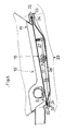
- the storage receptacle 1 is provided with unloading hoppers 2 and rests, via a chassis 3, on the running gear 4 of a vehicle 5 , like the bogies of a wagon.
- the body 6 of the receptacle 1 has, in its essential part 7, a generally cylindrical shape, of horizontal axis, closed at its ends by domed caps 8, 9, for example substantially hemispherical, giving said body 6 of the receptacle a horizontal section oblong whose longitudinal axis 10 is generally parallel to the direction of movement of the vehicle.
- the hoppers 2 are connected to the base of the body 6 so that the product which descends by gravity is channeled to outlet orifices 11 through which the hoppers 2 are connected to a drain line 12.
- These hoppers 2 have a flared shape, the widest part of which is situated at their upper part while the narrowest part is situated on the side of the outlet orifice 11.
- They include a wall 13, all of the generators 14 of which have a slope A of at least about fifty degrees.
- the receptacle is furthermore provided with fluidization means 15 comprising in known manner at least one screen 16 on which the product presses by its own weight and under which means 17 breathe air leading the products towards the drain line 12.
- the hoppers 2 have a horizontal section of oblong shape whose major axis is parallel to the longitudinal axis 10 of the receptacle 1.
- the side wall 13 of the hoppers has, on the one hand, spaced from each other by a certain distance X, two substantially semi-conical parts 18, 19 of slope A, the concavities of which are turned. towards each other, and, on the other hand, two flat walls 20, 21 of width corresponding to the distance X between the substantially semi-conical parts of which they join the extreme generatrices to produce the longitudinal sides of the oblong horizontal section of the hopper.
- this hopper can be connected with the body of the receptacle so that, in its lower part, at all points around the hopper, the body has , towards the outlet, a slope at least substantially constant in continuity with that of the wall of the hopper both in the parts where it is connected to the cylindrical part of the body and in the parts where the hopper is connected to a part domed body.
- the hoppers In the case where the tank has several hoppers, to ensure the emptying of the entire receptacle, the hoppers must obviously have their entrances which follow one another practically without interval.
- this oblong shape therefore reduces the number of hoppers necessary to equip the receptacle.
- the substantially semi-conical parts 18, 19 both extend over the same height and this practically up to their apex S while the two plane walls 20, 21 would then have a constant height equal to the generators 14 of these substantially semi-conical parts 18, 19 and - on the other hand, that the lower edge 22 of the hopper directly produces the orifice 11 connecting to the drain pipe 12, while the fluidization means would be housed inside the receptacle, according to another characteristic of the invention: - On the one hand, the two plane walls 20, 21 and at least one of the semi-conical parts 18, 19 are interrupted at their base at their intersection with a plane P inclined so that the lowest point B and the highest point H of the lower edge 22 of the wall 13 of the hopper 2 are located respectively at opposite points of the intersection of the lower edge 22 with the vertical plane passing through the longitudinal axis 10 of the hopper 2 and - on the other hand, it is under this lower edge 22 of the wall 13 of the hopper 2 that the fluidization means 15 are supported by means of which
- the foregoing provisions make it possible to improve the performance and characteristics of transport vehicles. While usually the hoppers of transport vehicles are conical or pyramidal shapes, the particularity of the present receiving hopper is to associate the hopper of the pyramidal type with that of the conical type.
- This arrangement has the advantage of guaranteeing a constant peripheral flow angle up to the fluidization means while ensuring an increase in useful capacity relative to the space between the substantially semi-conical parts.
- This arrangement also makes it possible to judiciously tilt the plane of the sieve of the fluidization means in order to ensure total emptying of the pulverulent products, through one or more outlet orifices, situated at the base of one of the half-cones.
- these fluidization means 15 are in the form of a carrier plate 23 having generally the shape of a bowl whose edge 24 is extended by a peripheral flange 25 cooperating with the lower edge 22 of hopper 2.
- the screen 16 supporting the product is held at its periphery by pinching between these two aforementioned elements 22, 25.
- the substantially horizontal base 26 of the carrier plate 23 adjoins the lowest point B previously stated.
- the air supply to the fluidization device 15 takes place through the side wall 27 of the carrier plate 23 by means of a pneumatic device permanently fixed to said plate and, therefore, easily accessible for the interview.
- This hopper design provides advantages in terms of improving the general characteristics of vehicles capable of transporting powdered products drained by a pneumatic system.
- this form of hopper allows: - a decrease in the number of hoppers (three instead of four), - a reduction in the length of the receptacles (approximately one meter) by recovery of the spaces between cones usually not used, - a reduction in the number and importance of the means necessary both for the air supply and for the product outlet (three hoppers and three fluidization means instead of four).
- This form also allows: - a dimensional standardization of the hoppers while ensuring the versatility of this equipment for the transport of various pulverulent products, chemical or food, due to the homogeneity of the walls further promoting the possible application of interior coatings, - a standardization of the fluidization means, the same means remaining valid for all products whether they are easy or difficult to fluidize, a reduction in the characteristics of the vehicles of the pressure drop in the proportions of the gain in number of hoppers and therefore in fluidization means, hence an improved unloading speed and a reduced emptying time, - better flow of the transported product due to the imbalance of the product due to the flat surface located between the half-cones.
Landscapes
- Engineering & Computer Science (AREA)
- Mechanical Engineering (AREA)
- Transportation (AREA)
- Health & Medical Sciences (AREA)
- Public Health (AREA)
- Filling Or Emptying Of Bunkers, Hoppers, And Tanks (AREA)
- Feeding, Discharge, Calcimining, Fusing, And Gas-Generation Devices (AREA)
- Air Transport Of Granular Materials (AREA)
- Vending Machines For Individual Products (AREA)
- Control Of Vending Devices And Auxiliary Devices For Vending Devices (AREA)
- Refuse Collection And Transfer (AREA)
Priority Applications (1)
| Application Number | Priority Date | Filing Date | Title |
|---|---|---|---|
| AT87402087T ATE55336T1 (de) | 1986-09-26 | 1987-09-18 | Lager- und transportbehaelter, an seiner basis versehen mit wenigstens einem entleerungstrichter. |
Applications Claiming Priority (2)
| Application Number | Priority Date | Filing Date | Title |
|---|---|---|---|
| FR8613899A FR2604407A1 (fr) | 1986-09-26 | 1986-09-26 | Receptacle de stockage et de transport pourvu a sa base d'au moins une tremie de dechargement |
| FR8613899 | 1986-09-26 |
Publications (2)
| Publication Number | Publication Date |
|---|---|
| EP0262035A1 true EP0262035A1 (de) | 1988-03-30 |
| EP0262035B1 EP0262035B1 (de) | 1990-08-08 |
Family
ID=9339584
Family Applications (1)
| Application Number | Title | Priority Date | Filing Date |
|---|---|---|---|
| EP87402087A Expired - Lifetime EP0262035B1 (de) | 1986-09-26 | 1987-09-18 | Lager- und Transportbehälter, an seiner Basis versehen mit wenigstens einem Entleerungstrichter |
Country Status (6)
| Country | Link |
|---|---|
| EP (1) | EP0262035B1 (de) |
| AT (1) | ATE55336T1 (de) |
| DD (1) | DD262400A5 (de) |
| DE (1) | DE3764228D1 (de) |
| ES (1) | ES2016639B3 (de) |
| FR (1) | FR2604407A1 (de) |
Cited By (4)
| Publication number | Priority date | Publication date | Assignee | Title |
|---|---|---|---|---|
| FR2811406A1 (fr) * | 2000-07-07 | 2002-01-11 | Arbel Fauvet Rail Sa | Conteneur citerne et notamment citerne pour gaz sous pression |
| EP1772310A1 (de) * | 2005-10-06 | 2007-04-11 | Vincenzo Munzio | Trichterstruktur |
| WO2013046072A1 (en) * | 2011-09-29 | 2013-04-04 | Legios Europe Ag. | Self-discharging railway wagon |
| CN110962719A (zh) * | 2019-12-19 | 2020-04-07 | 辽宁忠旺特种车辆制造有限公司 | 举升式粉粒物料运输半挂车 |
Citations (4)
| Publication number | Priority date | Publication date | Assignee | Title |
|---|---|---|---|---|
| US484527A (en) * | 1892-10-18 | Badge | ||
| GB955605A (en) * | 1960-11-08 | 1964-04-15 | Babcock & Wilcox Ltd | Improvements in or relating to dust conveying trucks |
| CH408989A (de) * | 1959-08-08 | 1966-03-15 | Interconsult Ab | Transportbehälter für pulverförmiges oder flüssiges Gut |
| FR1585873A (de) * | 1967-09-29 | 1970-02-06 |
Family Cites Families (1)
| Publication number | Priority date | Publication date | Assignee | Title |
|---|---|---|---|---|
| US4484527A (en) * | 1982-07-23 | 1984-11-27 | Acf Industries, Inc. | Convertible railway hopper car |
-
1986
- 1986-09-26 FR FR8613899A patent/FR2604407A1/fr active Pending
-
1987
- 1987-09-18 ES ES87402087T patent/ES2016639B3/es not_active Expired - Lifetime
- 1987-09-18 AT AT87402087T patent/ATE55336T1/de not_active IP Right Cessation
- 1987-09-18 DE DE8787402087T patent/DE3764228D1/de not_active Expired - Lifetime
- 1987-09-18 EP EP87402087A patent/EP0262035B1/de not_active Expired - Lifetime
- 1987-09-25 DD DD87307260A patent/DD262400A5/de not_active IP Right Cessation
Patent Citations (4)
| Publication number | Priority date | Publication date | Assignee | Title |
|---|---|---|---|---|
| US484527A (en) * | 1892-10-18 | Badge | ||
| CH408989A (de) * | 1959-08-08 | 1966-03-15 | Interconsult Ab | Transportbehälter für pulverförmiges oder flüssiges Gut |
| GB955605A (en) * | 1960-11-08 | 1964-04-15 | Babcock & Wilcox Ltd | Improvements in or relating to dust conveying trucks |
| FR1585873A (de) * | 1967-09-29 | 1970-02-06 |
Cited By (5)
| Publication number | Priority date | Publication date | Assignee | Title |
|---|---|---|---|---|
| FR2811406A1 (fr) * | 2000-07-07 | 2002-01-11 | Arbel Fauvet Rail Sa | Conteneur citerne et notamment citerne pour gaz sous pression |
| EP1772310A1 (de) * | 2005-10-06 | 2007-04-11 | Vincenzo Munzio | Trichterstruktur |
| WO2013046072A1 (en) * | 2011-09-29 | 2013-04-04 | Legios Europe Ag. | Self-discharging railway wagon |
| CZ307515B6 (cs) * | 2011-09-29 | 2018-11-07 | Legios Europe Ag | Železniční samovýsypný vůz |
| CN110962719A (zh) * | 2019-12-19 | 2020-04-07 | 辽宁忠旺特种车辆制造有限公司 | 举升式粉粒物料运输半挂车 |
Also Published As
| Publication number | Publication date |
|---|---|
| FR2604407A1 (fr) | 1988-04-01 |
| DD262400A5 (de) | 1988-11-30 |
| ATE55336T1 (de) | 1990-08-15 |
| EP0262035B1 (de) | 1990-08-08 |
| DE3764228D1 (de) | 1990-09-13 |
| ES2016639B3 (es) | 1990-11-16 |
Similar Documents
| Publication | Publication Date | Title |
|---|---|---|
| EP0116246B1 (de) | Behälterfülleinrichtung mit Feststoffpartikeln | |
| EP0769462A1 (de) | Verfahren und Vorrichtung zum gleichmässigen Verteilen von Feststoffen in fein verteilter Form, in einem Behälter | |
| EP0262035B1 (de) | Lager- und Transportbehälter, an seiner Basis versehen mit wenigstens einem Entleerungstrichter | |
| FR2558807A1 (fr) | Benne pour le stockage et le transport d'une charge | |
| NL7812680A (nl) | Werkwijze voor het lossen van poedervormige melamine uit een container, container geschikt voor het transport van melamine en hopper geschikt voor deze werkwijze. | |
| FR2608566A1 (fr) | Tremie basculante | |
| FR2505792A1 (fr) | Conteneur de transport | |
| EP2429925A1 (de) | Flexibler behälter zur verpackung von festpartikelmaterialien in loser form und verwendung | |
| FR2535374A1 (fr) | Silo pour produits en vrac | |
| FR2541715A1 (fr) | Fond de cellule perfectionne pour silo | |
| EP0389394B1 (de) | Schüttgutempfangs- und -sendegrube und Bunkeranlage einschliesslich einer solchen Grube | |
| FR2618131A1 (fr) | Conteneur du type perfectionne, plus particulierement pour le transport des grains | |
| EP0043321B1 (de) | Vorrichtung zum Entladen von Schüttgütern | |
| FR2579561A1 (fr) | Perfectionnements apportes aux reservoirs de stockage de matieres pulverulentes ou granuleuses | |
| US4363574A (en) | Method of emptying a powder or like material out of a container | |
| FR2644148A3 (fr) | Dispositif d'emplissage de conteneurs par un materiau en vrac | |
| FR2670472A1 (fr) | Convoyeur a bandes pour le transfert vertical ou suivant une forte pente de produits en vrac. | |
| FR2532606A1 (fr) | Remorque pour semi-remorque portant un recipient-silo basculable | |
| EP0691926A1 (de) | Mobile anlage mit schüttgutlagerungsmitteln, die eine schwerkraftausgabe des schüttguts zulassen und mit mitteln zum empfang der ausgegebenen produkten | |
| FR2493284A1 (fr) | Appareil pour la reprise au stock de matieres a l'etat de particules | |
| FR2683799A1 (fr) | Tremie en forme de caisson a fond vibrant. | |
| FR3132240A1 (fr) | Centrale à béton en libre-service | |
| FR2546027A1 (fr) | Dispositif d'epandage pour matiere pulverulente | |
| EP0090981A2 (de) | Transport- und Speichereinrichtung für Schüttgüter | |
| BE557126A (de) |
Legal Events
| Date | Code | Title | Description |
|---|---|---|---|
| PUAI | Public reference made under article 153(3) epc to a published international application that has entered the european phase |
Free format text: ORIGINAL CODE: 0009012 |
|
| AK | Designated contracting states |
Kind code of ref document: A1 Designated state(s): AT BE CH DE ES FR GB IT LI LU NL |
|
| 17P | Request for examination filed |
Effective date: 19880303 |
|
| 17Q | First examination report despatched |
Effective date: 19890329 |
|
| GRAA | (expected) grant |
Free format text: ORIGINAL CODE: 0009210 |
|
| AK | Designated contracting states |
Kind code of ref document: B1 Designated state(s): AT BE CH DE ES FR GB IT LI LU NL |
|
| REF | Corresponds to: |
Ref document number: 55336 Country of ref document: AT Date of ref document: 19900815 Kind code of ref document: T |
|
| ITF | It: translation for a ep patent filed | ||
| GBT | Gb: translation of ep patent filed (gb section 77(6)(a)/1977) | ||
| REF | Corresponds to: |
Ref document number: 3764228 Country of ref document: DE Date of ref document: 19900913 |
|
| PLBE | No opposition filed within time limit |
Free format text: ORIGINAL CODE: 0009261 |
|
| STAA | Information on the status of an ep patent application or granted ep patent |
Free format text: STATUS: NO OPPOSITION FILED WITHIN TIME LIMIT |
|
| 26N | No opposition filed | ||
| ITTA | It: last paid annual fee | ||
| PGFP | Annual fee paid to national office [announced via postgrant information from national office to epo] |
Ref country code: AT Payment date: 19930830 Year of fee payment: 7 |
|
| PGFP | Annual fee paid to national office [announced via postgrant information from national office to epo] |
Ref country code: BE Payment date: 19930831 Year of fee payment: 7 |
|
| PGFP | Annual fee paid to national office [announced via postgrant information from national office to epo] |
Ref country code: ES Payment date: 19930907 Year of fee payment: 7 |
|
| PGFP | Annual fee paid to national office [announced via postgrant information from national office to epo] |
Ref country code: GB Payment date: 19930908 Year of fee payment: 7 |
|
| PGFP | Annual fee paid to national office [announced via postgrant information from national office to epo] |
Ref country code: LU Payment date: 19930915 Year of fee payment: 7 |
|
| PGFP | Annual fee paid to national office [announced via postgrant information from national office to epo] |
Ref country code: FR Payment date: 19930921 Year of fee payment: 7 |
|
| PGFP | Annual fee paid to national office [announced via postgrant information from national office to epo] |
Ref country code: CH Payment date: 19930923 Year of fee payment: 7 |
|
| PGFP | Annual fee paid to national office [announced via postgrant information from national office to epo] |
Ref country code: NL Payment date: 19930930 Year of fee payment: 7 |
|
| PGFP | Annual fee paid to national office [announced via postgrant information from national office to epo] |
Ref country code: DE Payment date: 19931125 Year of fee payment: 7 |
|
| EPTA | Lu: last paid annual fee | ||
| PG25 | Lapsed in a contracting state [announced via postgrant information from national office to epo] |
Ref country code: LU Free format text: LAPSE BECAUSE OF NON-PAYMENT OF DUE FEES Effective date: 19940918 Ref country code: GB Effective date: 19940918 Ref country code: AT Effective date: 19940918 |
|
| PG25 | Lapsed in a contracting state [announced via postgrant information from national office to epo] |
Ref country code: ES Free format text: LAPSE BECAUSE OF EXPIRATION OF PROTECTION Effective date: 19940919 |
|
| PG25 | Lapsed in a contracting state [announced via postgrant information from national office to epo] |
Ref country code: LI Effective date: 19940930 Ref country code: CH Effective date: 19940930 Ref country code: BE Effective date: 19940930 |
|
| BERE | Be: lapsed |
Owner name: S.A. ARBEL FAUVET RAIL Effective date: 19940930 |
|
| PG25 | Lapsed in a contracting state [announced via postgrant information from national office to epo] |
Ref country code: NL Effective date: 19950401 |
|
| NLV4 | Nl: lapsed or anulled due to non-payment of the annual fee | ||
| GBPC | Gb: european patent ceased through non-payment of renewal fee |
Effective date: 19940918 |
|
| PG25 | Lapsed in a contracting state [announced via postgrant information from national office to epo] |
Ref country code: FR Effective date: 19950531 |
|
| REG | Reference to a national code |
Ref country code: CH Ref legal event code: PL |
|
| PG25 | Lapsed in a contracting state [announced via postgrant information from national office to epo] |
Ref country code: DE Effective date: 19950601 |
|
| REG | Reference to a national code |
Ref country code: FR Ref legal event code: ST |
|
| REG | Reference to a national code |
Ref country code: ES Ref legal event code: FD2A Effective date: 19990601 |
|
| PG25 | Lapsed in a contracting state [announced via postgrant information from national office to epo] |
Ref country code: IT Free format text: LAPSE BECAUSE OF NON-PAYMENT OF DUE FEES;WARNING: LAPSES OF ITALIAN PATENTS WITH EFFECTIVE DATE BEFORE 2007 MAY HAVE OCCURRED AT ANY TIME BEFORE 2007. THE CORRECT EFFECTIVE DATE MAY BE DIFFERENT FROM THE ONE RECORDED. Effective date: 20050918 |