EP0262338B1 - Procédé et appareil d'emballage automatique - Google Patents
Procédé et appareil d'emballage automatique Download PDFInfo
- Publication number
- EP0262338B1 EP0262338B1 EP87111264A EP87111264A EP0262338B1 EP 0262338 B1 EP0262338 B1 EP 0262338B1 EP 87111264 A EP87111264 A EP 87111264A EP 87111264 A EP87111264 A EP 87111264A EP 0262338 B1 EP0262338 B1 EP 0262338B1
- Authority
- EP
- European Patent Office
- Prior art keywords
- tape
- loop
- guide
- plate
- bed
- Prior art date
- Legal status (The legal status is an assumption and is not a legal conclusion. Google has not performed a legal analysis and makes no representation as to the accuracy of the status listed.)
- Expired - Lifetime
Links
Images





Classifications
-
- B—PERFORMING OPERATIONS; TRANSPORTING
- B65—CONVEYING; PACKING; STORING; HANDLING THIN OR FILAMENTARY MATERIAL
- B65B—MACHINES, APPARATUS OR DEVICES FOR, OR METHODS OF, PACKAGING ARTICLES OR MATERIALS; UNPACKING
- B65B13/00—Bundling articles
- B65B13/02—Applying and securing binding material around articles or groups of articles, e.g. using strings, wires, strips, bands or tapes
-
- B—PERFORMING OPERATIONS; TRANSPORTING
- B65—CONVEYING; PACKING; STORING; HANDLING THIN OR FILAMENTARY MATERIAL
- B65B—MACHINES, APPARATUS OR DEVICES FOR, OR METHODS OF, PACKAGING ARTICLES OR MATERIALS; UNPACKING
- B65B13/00—Bundling articles
- B65B13/02—Applying and securing binding material around articles or groups of articles, e.g. using strings, wires, strips, bands or tapes
- B65B13/04—Applying and securing binding material around articles or groups of articles, e.g. using strings, wires, strips, bands or tapes with means for guiding the binding material around the articles prior to severing from supply
- B65B13/06—Stationary ducts or channels
-
- Y—GENERAL TAGGING OF NEW TECHNOLOGICAL DEVELOPMENTS; GENERAL TAGGING OF CROSS-SECTIONAL TECHNOLOGIES SPANNING OVER SEVERAL SECTIONS OF THE IPC; TECHNICAL SUBJECTS COVERED BY FORMER USPC CROSS-REFERENCE ART COLLECTIONS [XRACs] AND DIGESTS
- Y10—TECHNICAL SUBJECTS COVERED BY FORMER USPC
- Y10T—TECHNICAL SUBJECTS COVERED BY FORMER US CLASSIFICATION
- Y10T156/00—Adhesive bonding and miscellaneous chemical manufacture
- Y10T156/10—Methods of surface bonding and/or assembly therefor
- Y10T156/1002—Methods of surface bonding and/or assembly therefor with permanent bending or reshaping or surface deformation of self sustaining lamina
- Y10T156/1028—Methods of surface bonding and/or assembly therefor with permanent bending or reshaping or surface deformation of self sustaining lamina by bending, drawing or stretch forming sheet to assume shape of configured lamina while in contact therewith
Definitions
- This invention relates to an automatic packaging apparatus for tightly binding packages with tape of a thermoplastic material such as polypropylene.
- US-A-4 079 667 and JP-A-49(1974)-4520 offered a method and apparatus comprised of an arc-shaped guide member covered by a band-end clamping base-plate provided near the surface of the work-table, whereby a packaging tape or band is fed from below the base-plate and along the guide member and the end of the band is then clamped to form a ring, the guide member is then removed from over the base-plate and more of the band is paid out to enlarge the ring into a loop, into which the merchandise is inserted and the band drawn tightly around it, the band being joined where it overlaps and cut.
- the object of the present invention is therefore to provide an automatic packaging method and apparatus whereby tangling of the tape loop by the guide member is prevented when the latter is retracted from the initial loop. This object is solved by contracting the loop to release it from the guide, by means of which the tape is prevented from falling out of the guide groove or from catching.
- An automatic packaging apparatus comprised of a transport mechanism which, when a guide that is swivellably provided on a packaging bed-plate for guiding packaging tape into a loop is set into position on the bed-plate by the urging of a solenoid, feeds the tape into and through the guide, and when the leading end of the tape is detected by a tape position detection switch provided at a specified position, a camshaft is activated and a section of the said tape is pressed and held by means of a fixing cylinder, the transport mechanism is reversed to contract the loop of tape, and after the guide is released from its position, the loop is formed to a specified size on the bed-plate and the object to be packaged is placed in the loop, and an ON signal from the work detection switch reverses the transport mechanism, binding the tape around the object, rotation of a camshaft is activated to operate a heating mechanism at the surfaces of the tape overlap, the overlapping tape surfaces being welded by a pressure-welding cylinder and excess tape cut off by a cutter on the pressure-weld
- an automatic packaging apparatus 1 is comprised of a main casing 2 on which is provided a bed-plate 3.
- a loop of packaging tape 4 composed of a thermoplastic material such as polypropylene.
- An object (now shown) to be packaged which is inserted into this loop pushes against a work detection switch 5 attached to the side of an extension 2a located at the left side of the bed-plate 3 of the main casing 2, to bind the packaging tape 4 in place around the object.
- the bed-plate 3 which also acts as the top cover of the main casing 2, is provided at its center with a groove 3a, the width of which is slightly greater than that of the packaging tape 4.
- the packaging tape 4 is raised at a specified position in the groove 3a to form the loop, and is inserted also into other positions in the groove 3a.
- the bed-plate 3 is divided at right-angles to the groove 3a, the right-hand section 3c of this divided section 3b being openable toward the back, as viewed in the figure.
- the packaging tape 4 is housed in a housing 6 provided inside this openable right-hand section 3c.
- a control circuit section 23 for the automatic packaging apparatus 1 is provided in the extension 2a of the main casing 2 on the left side of the divided section 3b, and a switch panel 24 containing power switches and the like is attached to the front of the extension 2a.
- the housing 6 is provided at the right-hand side of the chassis 2c of the main casing 2.
- a tape holder 4a which has wound thereon a roll of the packaging tape 4.
- a partition 6b is provided on the left side of this housing 6.
- the packaging tape 4 contained in the housing 6 is threaded through a tape-feeding opening 6c to the transport mechanism 7, to locate it in a guide 19 of a guide mechanism 18 on the bed-plate 3, whereupon the transport mechanism 7 is activated by a signal from the control circuit section 23, the packaging tape 4 thereby being moved along the guide 19 and formed into a loop.
- the leading end of the packaging tape 4 is detected by a tape position detection switch 21 and is fixed into position by means of the pressure-welding mechanism 9 located beneath the bed-plate 3. Then, under the urging in the opposite direction by the transport mechanism 7, the loop of packaging tape 4 contracts.
- the loop of packaging tape 4 contracts inside the guide 19, and the guide 19 is swivelled into the extension 2a so that it does not catch the packaging tape 4.
- the transport mechanism 7 is again activated and the packaging tape 4 is moved to form a loop of the specified size on the bed-plate 3, which is the state shown in Figure 1.
- the object to be packaged is placed inside the loop of packaging tape 4 on the bed-plate 3, pressing the work detection switch 5, the transport mechanism 7 reels in the packaging tape 4, binding the tape in place around the object.
- the control circuit section 23 confirms that this binding has been performed, the heating mechanism 16 is activated to heat the overlapping surfaces of the packaging tape 4 and the pressure-welding mechanism 9 is driven to pressure-weld the said overlapping surfaces.
- the cutter 14c of the pressure cylinder 14 provided on the pressure-welding mechanism 9 cuts off the excess packaging tape 4 to thereby complete the sequence of packaging operations.
- Figure 1 shows a side view of the automatic packaging apparatus 1.
- the transport mechanism 7, which performs the feeding and reeling-in of the packaging tape 4 is comprised of as tape inlet 7a positioned to correspond with the tape-feeding opening 6c provided in the portion 6b for communication therewith, and a guide channel 7b is formed as an extension of the tape inlet 7a.
- a drive roller 7d is provided at part of the guide channel 7b, and a guide roller 7c is provided which is in contact with the peripheral surface of the drive roller 7d. Downstream of the point of contact between the drive roller 7d and the guide roller 7c, the guide channel 7b is formed following the peripheral surface of the drive roller 7d and is connected at its end to a supply outlet 11 provided below the bed-plate 3.
- a movable plate 8 is provided over the supply outlet 11, and the inside of the supply outlet 11 is divided into an upper and a lower passage by an intermediate member 8a affixed below the movable plate 8.
- the end of the guide channel 7b is connected to the lower one of the passages divided by the movable plate 8.
- the drive roller 7d is connected to the shaft 7m of a separately-provided motor 7e ( Figure 8) and in accordance with command signals from the control circuit section 23 (described later) is rotated clockwise (forward) or counterclockwise (reverse).
- the guide roller 7c is rotatably supported by a support member 7f that is supported so that it can swing up and down with a screw 7g as the fulcrum.
- the support member 7f is constantly urged upwards by a coil spring 7h on a bolt 7i provided in a chassis 2c. Therefore, the guide roller 7c pressed against the drive roller 7d through the medium of the packaging tape 4 in the guide channel 7b rotates together with the rotation of the drive roller 7d, enabling the packaging tape 4 to be transported.
- the numeral 7j denotes a nut provided on the bolt 7i, the urging force of the coil spring 7h being adjustable by adjusting the position of this nut 7j.
- the front of the transport mechanism 7 is covered with a sheet of clear resin which is attached by a screw 7k.
- the pressure-welding mechanism 9 has as camshaft 10 which passes through the lower part of sidepl ates 9a, 9a provided vertically on the chassis 2c, a cylinder block 12 and a coupling member 9b.
- An engagement slot 9c is provided on the upper surface of the coupling member 9b, and by means of the engagement slot 9c the movable plate 8 provided beneath the bed-plate 3 is slidably attached so that it can be moved back and forth, with respect to the drawing of Figure 4.
- the movable plate 8 is provided with an intermediate member 8a which also is slidable back and forth with respect to Figure 4.
- the movable plate 8 and the intermediate member 8a are both urged in one direction (to the front, in Figure 4) by springs (not shown).
- the intermediate member 8a is located in the center of the supply outlet 11 provided directly beneath the movable plate 8, and is arranged so that the supply outlet 11 is divided in two.
- the movable plate 8 and intermediate member 8a are moved by the cam-plate 10e of the camshaft 10, as described later.
- the cylinder block 12 is affixed at a specified position on the sideplates 9a, 9a and is provided with three cylinder bores for the insertion of three cylinders. From the left in the figure, the cylinders are a tying cylinder 13, the pressure-welding/cutting cylinder 14 and a fixing cylinder 15. The three cylinders 13, 14 and 15 are inserted into the cylinder bores in the cylinder block 12 so as to be vertically slidable.
- the tying cylinder 13 has a main cylinder member 13a and an integrally formed solid block 13b at the top thereof, and provided inside the block 13b is a tape passage 13c, formed of sloping walls, through which the packaging tape 4 passes.
- An upper blade 13d is formed on the upper left edge of the tape passage 13c.
- a stepped section 13e is provided at the top of the tying cylinder 13.
- the pressure-welding/cutting cylinder 14, provided adjoining on the left of the tying cylinder 13 has a main cylinder member 14d which can slide in the cylinder.
- the top of a block section 14a provided at the upper part of the 14d is formed into a flat section 14b.
- This flat section 14b is for pressing the packaging tape 4 against the underside of the movable plate 8, and is provided with a cutter 14c on its right side.
- the cutter 14c abuts the left side of the tying cylinder 13, and in conjunction with the upper blade 13d of the tying cylinder 13 cuts off excess packaging tape 4 on the upstream side.
- the fixing cylinder 15 provided on the left of the pressure-welding/cutting cylinder 14 is provided with the top of a main cylinder member 15c with a block 15b having a projection 15a on its upper edge.
- the projection 15a on the block 15b can detachably engage with a groove section 9d on the underside of the movable plate 8 to clamp the packaging tape 4 on the downstream side.
- the above main cylinder members 13a, 14d and 15c each have a roller attached at the lower end, and cam plates 10a, 10b and 10c affixed to the camshaft 10 disposed beneath the rollers are urged into resilient contact therewith by a spring (not shown).
- the camshaft 10 is coupled to a motor 10f by means of a train of gearwheels, which is not shown in Figure 4, being off to the left (see Figure 2).
- a datum detection circuit 22, described later, is provided above the camshaft 10, which ensures the datum of the camshaft 10 and also detects inclination of the camshaft 10.
- Another cam-plate 10d is provided between the cam-plate 10a and the cam-plate 10b affixed on the camshaft 10, and another cam-plate 10e is provided between cam-plate 10b and cam-plate 10e. These cam-plates 10d and 10e work the heating mechanism 16 and the supply outlet 11 of the movable plate 8, respectively.
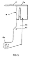
- the heating mechanism 16 is comprised of a bearing shaft 16a, which projects inwardly from the sideplates 9a, 9a beneath the camshaft 10, a shank 16b that rests on the bearing shaft 16a, and a heater member 17 provided at the top of the shank 16b ( Figure 5).
- the heater member 17 is a slab-shaped member, and a heating device is housed in a case 17a attached to the underside thereof, the heater member 17 providing heat at all times.
- a bearing hole 16c for holding a roller is provided in the intermediate section of the shank 16b of the heating mechanism 16. The roller affixed on the inner side of this bearing hole 16c is pressure-contacted with the cam-plate 10d on the camshaft 10 by means of a spring (not shown).
- the moving mechanism of the movable plate 8 is similar in construction to the cam mechanism of the heating mechanism 16.
- the heating mechanism 16 has a bearing shaft 16d provided on the opposite side to the bearing shaft 16a ( Figure 4), a shank 16e is slidably attached to the bearing shaft 16d, and via a roller attached to an intermediate section of the shank 16e, a spring provides pressure-contact with the cam-plate 10e on the camshaft 10, so that the rotation of the cam-plate 10e causes a back-and-forth rocking motion about the bearing shaft 16d.
- the top of the shank 16e communicates depthwise, with respect to the drawing, with the movable plate 8 and the intermediate member 8a, and in time with the swinging of the shank 16e, the movable plate 8 and intermediate member 8a are moved depthwise.
- the heater member 17 comes between the overlapping surfaces of the packaging tape 4 just as the intermediate member 8a is moved out from between the overlapping surfaces. Also, simultaneously with the completion of the welding of the packaging tape 4 by the pressure-welding/cutting cylinder 14, the movable plate 8 on top of the intermediate member 8a is moved depthwise out of the way by the turning action of the cam-plate 10e, enabling the object being packaged to be removed from the bed-plate 3.
- the guide mechanism 18 is provided on the adjoining left side of the pressure-welding mechanism 9 ( Figure 3).
- the guide mechanism 18 guides the packaging tape 4 conveyed from the transport mechanism 7 and forms it into a loop on the bed-plate 3.
- a solenoid 18a provided on the chassis 2c are a solenoid 18a, a rack 18b coupled to the actuator end of the solenoid 18a, a coil spring 18f ( Figure 2) which constantly urges the rack 18b to the right, and a toothed-belt pulley 18c coaxial with the gearwheel 18g that meshes with the rack 18b.
- a toothed-belt pulley 18d of the ame diameter is rotatably supported on the left-hand sideplate 9a of the pressure-welding mechanism 9, a toothed belt 18e runs vertically around the toothed-belt pulleys 18d and 18c, and the guide 19 is fixed on the same spindle as the toothed-belt pulley 18d.
- the guide 19 which is comprised of two flat, transparent sideplates 19b, 19b, is formed at one edge into a crescent shape, and on the other edge it is formed into a cutout section 19a which covers the movable plate 8 provided below the bed-plate 3.
- a shaft hole 19c Provided at one end of the flat sideplates 19b, 19b is a shaft hole 19c for the insertion thereinto of the spindle of the toothed-belt pulley 18d.
- a guide surface 20 that is formed slightly wider than the width of the packaging tape 4 and which follows the outer rim of the crescent.
- the end of the packaging tape 4 inserted into the left-hand side of the guide surface 20 is moved along the guide surface 20 to form a loop.
- the guide 19 With the rack 18b urged to the right by the coil spring 18f, the guide 19 is usually in an upright position (the position shown in Figure 3 by the double-dot chain line).
- the solenoid 18a is energized by a signal from the control circuit section 23, described later, the rack 18b is moved to the left, causing the pinion in engagement with the rack 18b to rotate clockwise.
- the left and right sides of the cutout portion 19a locate in the groove 3a of the bed-plate 3, the left side of the guide 19 is in alignment with the lower part of the supply outlet 11 and the right side with the upper part thereof. Therefore, the packaging tape 4 led through from the lower side of the guide 11 is guided by the guide surface 20 to the upper side of the supply outlet 11, to form a loop.
- the end of the tape 4 guided to the upper part of the outlet 11 comes into contact with a tape position detection switch 21 provided at the opening of guide 11 ( Figure 4).
- the signal from the tape position detection switch 21 stops the shaft 7m of the motor 7e in the transport mechanism 7, halting the transport of the tape 4.
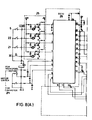
- the structure of the control circuit section 23 which controls each of the mechanisms of the automatic packaging apparatus 1 is shown in Figure 7.
- Contact input signals from the work detection switch 5, datum detection switch 22, tape position detection switch 21 and a tape-tightened signal input section 30 are sent to a contact input section 25.
- the output signal from this contact input section 25 is input to a gate control circuit 26 (Ic1).
- Contact input signals from the switch panel 24 are directly input into the gate control circuit 26.
- the gate control circuit 26 is a programmable logic array gate circuit which mainly discriminates the outputs of the contact input section 25, outputs signals to a switch circuit 27 and to the program timers Ic4, Ic5, Ic6, Ic7 and Ic8 for sequential control of the automatic packaging apparatus 1.
- the output side of the switch circuit 27 provided on the output side of the gate control circuit Ic1 is connected to the motor 7e, the motor 10f and the solenoid 18a.
- the program timer Ic7 is connected to the output terminal Ic1-22 of the gate control circuit Ic1, and controls the timing of the commands to energize the solenoid 18a for the positioning of the guide 19 on the bed-plate 3.
- the program timer Ic7 has a time constant circuit C13 to delay the energization of the solenoid 18 to prevent the guide 19 from being immediately positioned on the bed-plate 3 when the object to be packaged is separated from the work detection switch 5, the time constant being variable.
- the program timer Ic8 is connected to the program timer Ic7 and controls the timing of the commands to rotate the transport motor 7e forward to transport the packaging tape 4 along the guide 19.
- the program timer Ic8 has a time constant circuit C15 which delays the start of the motor 7e's forward rotation until the operation of the solenoid 18a has securely positioned the guide 19 on the bed-plate 3; the time constant circuit C15 is also provided with a variable resistor.
- the program timer Ic4 is connected to the output terminal Ic1-15 of the gate control circuit Ic1 and controls the timing of the commands to stop the reverse rotation of the motor 7e.
- the program timer Ic4 has a time constant circuit C7 to set the time of contraction of the loop of packaging tape 4 in the guide 19.
- the program timer Ic5 is connected to the program timer Ic4 and controls the timing of commands to rotate the motor 7e forward to expand the loop of tape again, and is provided with a time constant circuit C9 to confirm that the guide 19 is ins ide the extension 2a before th motor 7e is rotated forward.
- the program timer Ic6 is connected to the program timer Ic5 and controls the timing of commands to rotate the motor 7e forward to expand the loop of tape to a specified size that allows the insertion therein of the object to be packaged. All of the circuits are reset by the provision of an output signal from program timer Ic6 to input terminal Ic1-13 of the gate control circuit Ic1.
- the program timer Ic6 contains a time constant circuit C11 which controls the period of forward rotation of the motor 7e by the program timer Ic5 and sets the period of expansion of the loop of tape 4. Again, the resistance which sets the time constant is variable, enabling the size of the loop to be changed.
- a power supply circuit 28 supplies the various circuits with specified voltages (5V, 12V, 24V).
- a motor speed detection circuit (not shown) outputs a tape-tightened signal to a tape-tightened signal input section 30.
- This tape-tightened signal goes to input terminal Ic1-4 of gate control circuit Ic1, a signal is output from output terminal Ic1-19 of gate control circuit Ic1 to switch circuit 27 photocoupler PC7, the cam motor 10f is activated to displace the camshaft 10 to a specified position and the tape in the lower part of the supply outlet 11 is fixed in place by the projection 15a of the fixing cylinder 15 and the groove portion 9d of the movable plate 8.
- the camshaft 10 operates the heating mechanism 16 to insert the heater member 17 and apply heat at the overlapping portion of the tape 4.
- the camshaft 10 continues to turn, operating the pressure-welding cylinder 14 and retracting the heater member 17.
- the overlapping tape 4 portion is then pressure-welded by the lower surface of the movable plate 8 and the flat portion 14b on the pressure cylinder 14, while at the same time the tape 4 is cut by the combination of the cutter 14c and the upper blade 13d of the tying cylinder 13.
- the cam-plate 10e rotation as the camshaft 10 is returning to its datum causes the shank 16e to swing and the movable plate 8 to be moved depthwise, with respect to the drawing.
- the datum detection switch 22 supplies a signal to gate control circuit Ic1 input terminal Ic1-2, and from gate control circuit Ic1 output terminal Ic1-19 a signal is supplied via switch circuit 27 photocoupler PC7 to cam motor 10f drive relay PY2, stopping the driving of said cam motor 10f.
- the work detection switch 5 When the object bound by the tape is removed from the bed-plate 3, the work detection switch 5 is switched off, and this signal is supplied to gate control circuit Ic1 input terminal Ic1-1 and an output signal from gate control circuit Ic1 output terminal Ic1-22 is su pplied to program timer Ic7 via time constant circuit C13.
- an output signal from program timer Ic7 is supplied to gate control circuit Ic1 input terminal Ic1-8 and the output from gate control circuit Ic1 output terminal Ic1-18 is supplied to the solenoid 18a via switch circuit 27 photocoupler PC8.
- the solenoid 18a is thereby energized, driving the guide mechanism 18 to position the guide 19 on the bed-plate 3.
- the time constant circuit C13 functions so that the guide 19 is not driven the instant the object is removed from the work detection switch 5, eliminating the risk that the operator may be injured by such instantaneous positioning.
- the output of the program timer Ic7 is supplied to program timer Ic8 via time constant circuit C15, and the output of program timer Ic8 is supplied to gate control circuit Ic1 input terminal Ic1-9.
- a signal from gate control circuit Ic1 output terminal Ic1-20 is supplied to the transport motor 7e forward relay PY3 via switch circuit 27 photocoupler PC6. As a result, the motor 7e performs forward rotation, feeding the tape through the guide 19.
- the tape is only moved through the guide 19 after the guide 19 has been securely positioned on the bed-plate 3.
- a signal from the said detection switch 21 is input to gate control circuit Ic1 input terminal Ic1-3, via contact input circuit 25.
- a signal from gate control circuit Ic1 output terminal Ic1-19 is supplied to relay PY2, via switch circuit 27 photocoupler PC7, driving the cam motor 10f and thereby turning the camshaft 10, and the stepped portion 13e of the tying cylinder 13 functions in combination with the lower surface of the movable plate 8 to hold the free end of the tape just before the supply outlet 11, and at the same time the datum detection switch 22 is switched off.
- an output signal from gate control circuit Ic1 output terminal Ic1-15 is also supplied to the program timer Ic4 via the time constant circuit C7.
- the output of the program timer Ic4 is suppied to gate control circuit Ic1 input terminal Ic1-10, and from the gate control circuit Ic1 output terminal Ic1-21 a signal is supplied via switch circuit 27 photocoupler PC5 to relay PY1.
- switch circuit 27 photocoupler PC5 to relay PY1.
- the signal from the program timer Ic4 output terminal is supplied to program timer Ic5 via the time constant circuit C9.
- the program timer Ic5 outputs a signal from output terminal Ic5-3 after the period of time set by the time constant circuit C9 has elapsed, i.e., after the contracted loop has definitely separated from the guide 19.
- the output signal from the program timer Ic5 is supplied to gate control circuit Ic1 input terminal Ic1-11, and from gate control circuit Ic1 output terminal Ic1-20 an output goes to relay PY3 via switch circuit 27 photocoupler PC6.
- the motor 7e rotates forward and expansion of the loop of tape starts.
- an output signal from program timer Ic5 is supplied, via time constant circuit C11, to the program timer Ic6.
- the program timer Ic6 supplies a signal to the reset terminal Ic1-13 of gate control circuit Ic1.
- gate control circuit Ic1 is reset, reverting to its initial state, while at the same time a signal from output terminal Ic1-20 is also supplied to relay PY3, via the switch circuit 27 photocoupler PC6.
- the rotation of the motor 7e is stopped, with the loop of tape on the bed-plate 3 at a size capable of allowing the packaging object to be inserted therein.
- the size of the expanded loop of tape is determined by the time constant circuit C11. This means that after the expanded loop has been formed on the bed-plate 3, it is possible to repeat the process to tie the tape around subsequent packaging objects.
- a monitor switch provided on the switch panel 24 allows the loop to be expanded by causing the transport motor 7e to rotate forward.
- the monitor switch it is also possible for the monitor switch to be used to reverse the transport mechanism. Also, if the timing of the camshaft 10 operation is off, a cam monitor switch can be used to adjust the timing apropriately.
- an automatic packaging apparatus wherein tape fed by a transport mechanism is formed into a loop by means of a guide that is swivellably provided on a packaging bed-plate, the leading end of the tape is detected by a tape position detection switch, the detection signal drives a cam motor, a section of the said tape is held, the transport mechanism being reversed at this time to contract the loop of tape, and after the guide has been retracted, the loop is expanded to the specified size, the object to be packaged is placed in the loop and the work detection switch is operated to reverse the transport mechanism, binding the tape around the object, at which time the surfaces of the tape overlap are heated and then welded by a pressure-welding cylinder and excess tape cut off, said transport mechanism being controlled by timing control circuits on the basis of contact input control circuits and signals discriminated by a gate control circuit, a one-piece guide being used from which the packaging tape does not not fall out or catch on or the like.
Landscapes
- Engineering & Computer Science (AREA)
- Mechanical Engineering (AREA)
- Basic Packing Technique (AREA)
Claims (3)
- Procédé d'emballage automatique comprenant les étapes de:
amenée, depuis une sortie d'alimentation (11) prévue au-dessous d'une plaque d'appui (3), sur laquelle est placé un objet à emballer, d'une bande d'emballage (4), de manière que la bande (4) suive une surface de guidage (20), située au-dessus de la plaque d'appui (3) et forme une boucle, et son extrémité étant stoppée au niveau de la sortie d'alimentation (11),
fixation d'une partie de la bande d'emballage, au niveau de la sortie d'alimentation (11),
à l'état de sortie de la boucle depuis la surface de guidage (20), le procédé d'amenée amène la bande (4) depuis la sortie d'alimentation (11) et agrandit la boucle selon la taille de l'objet à envelopper, et
placement de l'objet à emballer sur la plaque d'appui (3), dans la boucle agrandie, étirement dans la boucle en vue de cercler la bande (4) autour de l'objet, soudage des surfaces de chevauchement de la bande (4) et découpage de cette bande au niveau du côté de sortie d'alimentation,
caractérisé en ce que la fixation de la bande d'emballage (4) est suivie par l'enroulement partiel de la bande (4), pour resserrer la boucle formée en alignement avec la surface de guidage (20). - Appareil d'emballage automatique comprenant:
un mécanisme de guidage (18), monté à pivotement à proximité de la plaque d'appui (3) sur laquelle l'objet à emballer est placé, et présentant une surface de guidage (20) pour guider la bande (4), afin de former une boucle sur la plaque d'appui (3),
un mécanisme de transport (7), qui amène la bande (4) le long de la surface de guidage (20), via la sortie d'alimentation (11) prévue au-dessous de la plaque d'appui (3), stoppe la bande (4) au niveau de la sortie d'amenée (11), à l'aide d'un commutateur de détection de position de bande (21), forme une boucle, agrandit la boucle jusqu'à une taille déterminée et, grâce à un signal d'entrée provenant d'un commutateur de détection (5), serre la boucle de bande autour de l'objet à emballer,
un mécanisme de soudage par pression (9), pourvu d'un cylindre de ficelage (13), qui peut être pressé contre un organe de couplage (9b) positionné au niveau de la sortie d'alimentation (11), pour maintenir une partie de la bande (4), un cylindre de soudage par pression (14) associé au cylindre de ficelage (13) pour souder par pression les surfaces de chevauchement de la boucle, des dispositifs de découpage (14c) situés sur les surfaces coulissantes du cylindre de ficelage (13) et du cylindre de soudage par pression (14), pour découper la longueur de bande en excès, un cylindre de fixation (15) associé au cylindre de soudage par pression (14), pour serrer la bande (4), et un arbre à cames (10) qui actionne lesdits cylindres (13, 14, 15),
un mécanisme de chauffage (16), pour chauffer les parties de chevauchement de la bande, conjointement avec la rotation de l'arbre à cames (10),
un mécanisme de sortie d'alimentation, pour déplacer la bande provenant de ladite sortie d'alimentation (11) située au-dessous de la plaque d'appui (3) et la relâcher, conjointement avec la rotation de l'arbre à cames (10),
une section de circuit de commande (23), comprenant un circuit de commande à porte (26), dans lequel entrent des signaux d'entrée provenant de circuits d'entrée (27) de contact de commutateur, sélectionne lesdits signaux d'entrée et les dirige vers les circuits prédéterminés, actionne, via les circuits de commutateur (27) reliés au circuit de commande à porte (26), un moteur de transport (7e) destiné à assurer l'entraînement avant et arrière du mécanisme de transport (7), un moteur de cames (10f) pour entraîner le mécanisme de soudage par pression (9) et un solénoïde (18a), pour faire pivoter le mécanisme de guidage (18), et un circuit de commande de synchronisation pour commander la synchronisation desdites parties d'entraînement reliées au circuit de commande à porte (26),
caractérisé en ce que ledit circuit de commande à porte (26) actionne ledit moteur de transport (7e) dans le sens inverse de celui assurant l'enroulement partiel de la bande (4), après la formation de la bande guidée par le mécanisme de guidage (18), de manière que la boucle soit serrée avant le pivotement du mécanisme de guidage (18), dans sa position non-fonctionnelle. - Appareil d'emballage automatique selon la revendication 2, dans lequel le mécanisme de guidage (18) comprend un guide (19), consistant en deux plaques planes (19b, 19b) congruentes, formées sur un bord en une forme semi-circulaire et sur l'autre, en une section découpée (19a), qui se situe dans une rainure (3a) de la plaque d'appui (3) et qui présente, à une extrémité, un orifice d'arbre (19c), pour l'insertion d'un tourillon cannelé, présentant un espace entre les plaques planes (19b, 19b), traversées par la bande (4), et une surface de guidage (20) située sur le côté semi-circulaire, ledit guide (19) présentant une première poulie (18d) fixée sur ledit tourillon couplé, par une courroie (18e), à une seconde poulie (18c), qui est en prise, via un pignon, avec une crémaillère (18b), qui s'étend depuis un solénoïde (18a), en entraînant ainsi en rotation le guide (19), lorsque le solénoïde (18a) est activé.
Applications Claiming Priority (2)
| Application Number | Priority Date | Filing Date | Title |
|---|---|---|---|
| JP201227/86 | 1986-08-29 | ||
| JP61201227A JPS6367212A (ja) | 1986-08-29 | 1986-08-29 | 自動梱包方法及び装置 |
Publications (2)
| Publication Number | Publication Date |
|---|---|
| EP0262338A1 EP0262338A1 (fr) | 1988-04-06 |
| EP0262338B1 true EP0262338B1 (fr) | 1992-12-02 |
Family
ID=16437440
Family Applications (1)
| Application Number | Title | Priority Date | Filing Date |
|---|---|---|---|
| EP87111264A Expired - Lifetime EP0262338B1 (fr) | 1986-08-29 | 1987-08-04 | Procédé et appareil d'emballage automatique |
Country Status (8)
| Country | Link |
|---|---|
| US (1) | US4836873A (fr) |
| EP (1) | EP0262338B1 (fr) |
| JP (1) | JPS6367212A (fr) |
| KR (1) | KR880002724A (fr) |
| DE (1) | DE3782908D1 (fr) |
| HK (1) | HK105293A (fr) |
| MY (1) | MY100967A (fr) |
| SG (1) | SG55293G (fr) |
Families Citing this family (17)
| Publication number | Priority date | Publication date | Assignee | Title |
|---|---|---|---|---|
| CA2117504A1 (fr) * | 1993-09-20 | 1995-03-21 | Karl M. Kropp | Scelleuse de boites equipee d'un systeme de detection servant a guider et a controler l'application du ruban adhesif |
| US5989216A (en) * | 1995-06-29 | 1999-11-23 | Sims Deltec, Inc. | Access portal and method |
| US6487833B1 (en) * | 2000-01-29 | 2002-12-03 | Howard W. Jaenson | Strap welding system and method |
| US6553900B1 (en) * | 2000-03-31 | 2003-04-29 | L&P Property Management Company | Three-part wire return for baling machine |
| JP4493831B2 (ja) * | 2000-11-16 | 2010-06-30 | ストラパック株式会社 | バンド掛け梱包機におけるコントロール装置 |
| DE50103301D1 (de) * | 2000-11-20 | 2004-09-23 | Ferag Ag | Umreifungsvorrichtung |
| US6571531B2 (en) * | 2001-04-02 | 2003-06-03 | Illinois Tool Works, Inc. | Strap detector assembly |
| US6966163B2 (en) * | 2002-10-11 | 2005-11-22 | Chs Acquisition Corp. | Method for banding product and apparatus therefor |
| DE102004008469A1 (de) * | 2004-02-20 | 2005-09-08 | Heidelberger Druckmaschinen Ag | Vorrichtung zum Banderolieren von Stapeln flächiger Werkstücke |
| US7665498B2 (en) * | 2005-11-15 | 2010-02-23 | 3M Innovative Properties Company | Tape monitoring system |
| US8365508B2 (en) * | 2009-10-21 | 2013-02-05 | Jason David Kenney | Banding of products |
| CH705743A2 (de) | 2011-11-14 | 2013-05-15 | Illinois Tool Works | Umreifungsvorrichtung. |
| CH705745A2 (de) * | 2011-11-14 | 2013-05-15 | Illinois Tool Works | Umreifungsvorrichtung. |
| US11021282B2 (en) * | 2017-07-19 | 2021-06-01 | Signode Industrial Group Llc | Strapping device configured to carry out a strap-attachment check cycle |
| CN107554846A (zh) * | 2017-09-26 | 2018-01-09 | 佛山科学技术学院 | 一种带准直功能的自动旋转打包机 |
| JP7348624B2 (ja) * | 2019-06-05 | 2023-09-21 | 株式会社寺岡精工 | 包装装置、包装方法 |
| US12503266B2 (en) | 2022-10-18 | 2025-12-23 | Signode Industrial Group Llc | Strapping device configured to dynamically adjust a tension parameter |
Family Cites Families (31)
| Publication number | Priority date | Publication date | Assignee | Title |
|---|---|---|---|---|
| GB936718A (fr) * | ||||
| US1357883A (en) * | 1917-01-06 | 1920-11-02 | Mcchesney John Sherman | Wire-tying |
| DE1153318B (de) * | 1959-11-05 | 1963-08-22 | Ver Metaalverpakking Mij Nv | Maschine zum Befestigen eines Metallbandes oder eines Metalldrahtes um eine Kiste, eine Dose, ein Paket oder ein anderes Packstueck |
| CH388182A (de) * | 1961-10-20 | 1965-02-15 | Fromm Gmbh A | Maschine zur Herstellung von Verschnürungen |
| US3146694A (en) * | 1961-10-27 | 1964-09-01 | Acme Steel Co | Strapping method and apparatus |
| US3215064A (en) * | 1964-05-25 | 1965-11-02 | A J Gerrard Mfg Co | Automatic strapping and sealing machine |
| US3442732A (en) * | 1965-08-13 | 1969-05-06 | Signode Corp | Friction-fusion strap sealing |
| US3442735A (en) * | 1965-08-13 | 1969-05-06 | Signode Corp | Friction-fusion strap sealing |
| US3447447A (en) * | 1967-02-21 | 1969-06-03 | Stanley Works | Strapping mechanism |
| US3493018A (en) * | 1968-01-22 | 1970-02-03 | Signode Corp | Strap straightening device |
| US3494280A (en) * | 1968-06-10 | 1970-02-10 | Signode Corp | Torsion bar sealing mechanism |
| US3566778A (en) * | 1969-01-27 | 1971-03-02 | Signode Corp | Strap feeding and tensioning system |
| US3554844A (en) * | 1969-04-07 | 1971-01-12 | Charles J Ingram | Tying device |
| US3636861A (en) * | 1970-04-20 | 1972-01-25 | Interlake Steel Corp | Strapping machine |
| US3718526A (en) * | 1971-02-25 | 1973-02-27 | Signode Corp | Apparatus for friction fusing |
| US3691939A (en) * | 1971-04-16 | 1972-09-19 | Imc Corp | Method and apparatus for binding packages |
| SU391013A1 (ru) * | 1972-02-04 | 1973-07-25 | Устройство для формирования пачек к обвязочным машинам | |
| JPS533315B2 (fr) * | 1972-03-18 | 1978-02-04 | ||
| JPS528095B2 (fr) * | 1972-04-24 | 1977-03-07 | ||
| US3916779A (en) * | 1972-05-26 | 1975-11-04 | Erapa Ag | Tape-clamping device |
| IT994112B (it) * | 1972-07-27 | 1975-10-20 | Mugishima M | Macchina da imballaggio |
| CH542749A (de) * | 1973-01-22 | 1973-10-15 | Erapa Ag | Vorrichtung zur Lagefixierung der Bandenden im Verschlussblock einer Maschine zum selbsttätigen Umschnüren bzw. Umreifen von Packstücken mit Bandmaterial |
| US3875855A (en) * | 1973-04-09 | 1975-04-08 | Stanley Works | Strapping method |
| DE2403261C3 (de) * | 1974-01-24 | 1978-07-20 | Maryan 5443 Kaisersesch Stankovicc-Gansen | Vorrichtung zum automatischen Umreifen |
| US4079667A (en) * | 1976-12-20 | 1978-03-21 | Signode Corporation | Method of forming and tensioning a strap loop about a package |
| US4077313A (en) * | 1976-12-20 | 1978-03-07 | Signode Corporation | Method of tensioning and joining a formed strap loop about a package |
| US4062278A (en) * | 1976-12-20 | 1977-12-13 | Signode Corporation | Expanding strap loop forming and friction fusion machine |
| JPS55164103U (fr) * | 1979-05-14 | 1980-11-26 | ||
| US4378262A (en) * | 1981-02-04 | 1983-03-29 | Signode Corporation | Method and apparatus for forming and tensioning a strap loop about a package |
| JPS5836409A (ja) * | 1981-08-26 | 1983-03-03 | Mitsubishi Chem Ind Ltd | 熱可塑性合成樹脂成形品の溶着方法及び装置 |
| DE3220445C2 (de) * | 1982-05-29 | 1985-10-17 | Hoesch Ag, 4600 Dortmund | Vorrichtung zum Spannen eines um ein Packstück gelegten Umreifungsbandes und zum Verbinden der sich überlappenden Enden des Umreifungsbandes |
-
1986
- 1986-08-29 JP JP61201227A patent/JPS6367212A/ja active Pending
-
1987
- 1987-08-04 DE DE8787111264T patent/DE3782908D1/de not_active Expired - Lifetime
- 1987-08-04 EP EP87111264A patent/EP0262338B1/fr not_active Expired - Lifetime
- 1987-08-25 KR KR870009294A patent/KR880002724A/ko not_active Withdrawn
- 1987-08-25 MY MYPI87001449A patent/MY100967A/en unknown
- 1987-08-28 US US07/090,745 patent/US4836873A/en not_active Expired - Lifetime
-
1993
- 1993-04-30 SG SG552/93A patent/SG55293G/en unknown
- 1993-10-07 HK HK1052/93A patent/HK105293A/en not_active IP Right Cessation
Also Published As
| Publication number | Publication date |
|---|---|
| DE3782908D1 (de) | 1993-01-14 |
| JPS6367212A (ja) | 1988-03-26 |
| EP0262338A1 (fr) | 1988-04-06 |
| HK105293A (en) | 1993-10-15 |
| MY100967A (en) | 1991-06-15 |
| US4836873A (en) | 1989-06-06 |
| SG55293G (en) | 1993-07-09 |
| KR880002724A (ko) | 1988-05-10 |
Similar Documents
| Publication | Publication Date | Title |
|---|---|---|
| EP0262338B1 (fr) | Procédé et appareil d'emballage automatique | |
| US6668516B2 (en) | Packing apparatus | |
| RU2249548C1 (ru) | Автоматическая машина для упаковки и бандажирования | |
| JP4171711B2 (ja) | トラック内に配置された物品を結束するための装置 | |
| DE69525774T2 (de) | Rotationsschablonendruckmaschine | |
| AU3473693A (en) | Laser tablet treatment system with dual access to tablet | |
| NL8201416A (nl) | Inrichting voor het spannen, sluiten en afsnijden van kunststofbanden bestemd voor het bundelen van materiaal. | |
| EP1405791B1 (fr) | Procédé pour réalimenter une bande de cerclage et machine à bander | |
| US4519733A (en) | Method and apparatus for automatically exchanging a workpiece in a machine tool | |
| JPH0152255B2 (fr) | ||
| US3577909A (en) | Automatic strapping machine | |
| JPH0620061U (ja) | 製本機 | |
| NL8403677A (nl) | Inrichting voor het aanbrengen van een band om een pakket. | |
| JPH04215909A (ja) | 梱包方法および装置 | |
| KR100430720B1 (ko) | 밴딩 포장기 컨트롤러 | |
| JP3002127B2 (ja) | ストレッチフィルム包装機におけるフィルム切換え送出し装置 | |
| KR200227463Y1 (ko) | 다양한 크기의 물건을 결속할 수 있는 반자동 결속기 | |
| JP3031770B2 (ja) | 梱包機のプールフィードユニットによるバンドリールのバンド弛み取り方法 | |
| JPH01254512A (ja) | バンド結束機 | |
| JP2935621B2 (ja) | 梱包機 | |
| US4005829A (en) | Tape roll and core | |
| US3223128A (en) | Adjustable saw blade control system for end trimmer apparatus | |
| JP3512884B2 (ja) | 結束装置 | |
| JPH07172404A (ja) | 梱包機 | |
| JPS63218021A (ja) | 紙束帯封装置 |
Legal Events
| Date | Code | Title | Description |
|---|---|---|---|
| PUAI | Public reference made under article 153(3) epc to a published international application that has entered the european phase |
Free format text: ORIGINAL CODE: 0009012 |
|
| AK | Designated contracting states |
Kind code of ref document: A1 Designated state(s): DE FR GB |
|
| 17P | Request for examination filed |
Effective date: 19881006 |
|
| 17Q | First examination report despatched |
Effective date: 19900822 |
|
| GRAA | (expected) grant |
Free format text: ORIGINAL CODE: 0009210 |
|
| AK | Designated contracting states |
Kind code of ref document: B1 Designated state(s): DE FR GB |
|
| PG25 | Lapsed in a contracting state [announced via postgrant information from national office to epo] |
Ref country code: DE Effective date: 19921202 Ref country code: FR Effective date: 19921202 |
|
| REF | Corresponds to: |
Ref document number: 3782908 Country of ref document: DE Date of ref document: 19930114 |
|
| EN | Fr: translation not filed | ||
| PLBE | No opposition filed within time limit |
Free format text: ORIGINAL CODE: 0009261 |
|
| STAA | Information on the status of an ep patent application or granted ep patent |
Free format text: STATUS: NO OPPOSITION FILED WITHIN TIME LIMIT |
|
| 26N | No opposition filed | ||
| REG | Reference to a national code |
Ref country code: GB Ref legal event code: IF02 |
|
| PGFP | Annual fee paid to national office [announced via postgrant information from national office to epo] |
Ref country code: GB Payment date: 20060731 Year of fee payment: 20 |
|
| PG25 | Lapsed in a contracting state [announced via postgrant information from national office to epo] |
Ref country code: GB Free format text: LAPSE BECAUSE OF EXPIRATION OF PROTECTION Effective date: 20070803 |