EP0262442A2 - Dispositif pour le triage et le transport de pièces découpées en tôle - Google Patents
Dispositif pour le triage et le transport de pièces découpées en tôle Download PDFInfo
- Publication number
- EP0262442A2 EP0262442A2 EP87112844A EP87112844A EP0262442A2 EP 0262442 A2 EP0262442 A2 EP 0262442A2 EP 87112844 A EP87112844 A EP 87112844A EP 87112844 A EP87112844 A EP 87112844A EP 0262442 A2 EP0262442 A2 EP 0262442A2
- Authority
- EP
- European Patent Office
- Prior art keywords
- sheet metal
- sorting
- knife
- slide
- scissor
- Prior art date
- Legal status (The legal status is an assumption and is not a legal conclusion. Google has not performed a legal analysis and makes no representation as to the accuracy of the status listed.)
- Withdrawn
Links
Images

Classifications
-
- B—PERFORMING OPERATIONS; TRANSPORTING
- B21—MECHANICAL METAL-WORKING WITHOUT ESSENTIALLY REMOVING MATERIAL; PUNCHING METAL
- B21D—WORKING OR PROCESSING OF SHEET METAL OR METAL TUBES, RODS OR PROFILES WITHOUT ESSENTIALLY REMOVING MATERIAL; PUNCHING METAL
- B21D43/00—Feeding, positioning or storing devices combined with, or arranged in, or specially adapted for use in connection with, apparatus for working or processing sheet metal, metal tubes or metal profiles; Associations therewith of cutting devices
- B21D43/28—Associations of cutting devices therewith
- B21D43/287—Devices for handling sheet or strip material
Definitions
- the invention relates to a device for sorting sheet metal sections of different widths and for removing these sections from the area of a long knife shear on which these cuts are produced.
- the sheet metal sections produced in this way fall behind the long knife shear into a container provided or are removed from the scissor area by a conveyor belt which is perpendicular to the cutting direction.
- a disadvantage of this method is that sections of different widths are stacked on top of one another, which then have to be sorted manually and sections which are too small slip off these conveyor belts during removal with conveyor belts and lead to malfunctions.
- the object of the invention is based on the object of designing a device of the type in question in a simple manner in such a way that sections of different widths can be sorted out of the scissors area.
- This object is achieved according to the invention in that at least two conveyor belts are arranged parallel to the scissor table in the area of the cut off sections falling off the knife, and these are loaded with the sections by means of a switch, in such a way that sections of the same width are always on one and the same Conveyor belt fall.
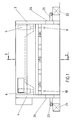
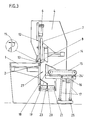
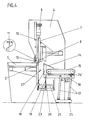
- the long knife scissors have a scissors table 1 with the scissors lower knife 2.
- the scissors table 1 lies on the supports of the side stands 3, 4.
- the upper scissor knife 8 is attached to this cutter bar 7.
- the lower scissor knife 2 can be placed against the upper scissor knife 8 in such a way that a cutting gap 11 is created between the lower scissor knife 2 and the upper scissor knife 8.
- the width of the cutting gap 11 is dependent on the sheet to be cut with the lower scissor knife 2 and the upper scissor knife 8 with regard to sheet thickness and sheet quality.
- the cutting gap 11 can also be set automatically under computer control by means of a device (not shown).
- hydraulically operated hold-down devices 13 are arranged in front of the cutter bar 7 on a hold-down plate 12, which press the sheet to be cut onto the scissor table 1 during the cutting process. Since the pressing force of the hold-down device depends on the cutting force, the hold-down force is automatically adjusted to the cutting force by a hydraulic system.
- the cut larger sheet metal sections reach an inclined chute 14 and are transported with a motor-driven conveyor belt 15 from the scissors area into a stacking device, not shown.
- the inclined slide 14 is mounted on holding arms 16 which can be pneumatically pulled perpendicular to the scissor-type lower knife 2 by means of a linkage 17.
- the inclined chute 14 is also pulled away from the lower scissor knife 2. This creates a space between the lower scissor knife 2 on the one hand and the baffle wall 18 of the inclined chute 14 on the other.
- the sheet metal sections can fall vertically downwards.
- a sorting tape 19 which can be pivoted pneumatically around a pivot point 20.
- a bevel is formed which is formed by the sorting flap 19.
- the falling sheet metal sections fall onto the sorting flap 19 and slide onto a transverse conveyor belt 21 which is arranged parallel to the scissor-type lower knife 2. This transports the fallen sheet metal sections sideways out of the scissors area into a transport container 22, which stands next to the scissors stand.
- the sorting flap 19 is in a vertical position, the sheet metal sections fall onto the transverse conveyor belt 23, which is located next to the transverse conveyor belt 21.
- the cross conveyor belt 23 transports the sheet metal sections on the other side of the scissors sideways out of the scissors into a transport container 24, which stands next to the scissor stand.
- the long knife shears have an electrical control which is connected to the control of the device according to the invention. It is thus possible to preselect the position of the inclined chute 14 and the position of the sorting flap 19 in such a way that the desired positions of both the inclined chute 14 and the position of the sorting flap 19 are determined depending on the cutting sequence.
- the inclined slide 14 with the holding arms 16 and the linkage 17 is attached to a frame 24 ', on which the motor-driven conveyor belt 15 is located, so that inclined slide 14, holding arms 16, linkage 17 and conveyor belt 15 form a structural unit.
- This unit is equipped with rollers 25, which make it possible to pull the entire unit easily out of the scissors area if required.
Landscapes
- Engineering & Computer Science (AREA)
- Mechanical Engineering (AREA)
- Accessories And Tools For Shearing Machines (AREA)
- Separation, Sorting, Adjustment, Or Bending Of Sheets To Be Conveyed (AREA)
- Shearing Machines (AREA)
Applications Claiming Priority (2)
| Application Number | Priority Date | Filing Date | Title |
|---|---|---|---|
| DE19863633730 DE3633730A1 (de) | 1986-10-03 | 1986-10-03 | Vorrichtung zum sortieren und transportieren von blechzuschnitten |
| DE3633730 | 1986-10-03 |
Publications (2)
| Publication Number | Publication Date |
|---|---|
| EP0262442A2 true EP0262442A2 (fr) | 1988-04-06 |
| EP0262442A3 EP0262442A3 (fr) | 1989-04-26 |
Family
ID=6311003
Family Applications (1)
| Application Number | Title | Priority Date | Filing Date |
|---|---|---|---|
| EP87112844A Withdrawn EP0262442A3 (fr) | 1986-10-03 | 1987-09-03 | Dispositif pour le triage et le transport de pièces découpées en tôle |
Country Status (2)
| Country | Link |
|---|---|
| EP (1) | EP0262442A3 (fr) |
| DE (1) | DE3633730A1 (fr) |
Cited By (4)
| Publication number | Priority date | Publication date | Assignee | Title |
|---|---|---|---|---|
| EP0589543A3 (en) * | 1992-09-23 | 1994-07-13 | Mannesmann Ag | Device for sorting and guiding of work pieces |
| EP0945196A3 (fr) * | 1998-03-21 | 2001-08-01 | Trumpf GmbH & Co | Dispositif pour trier les pièces à d'une machine pour couper des pièces de travail |
| CN102513594A (zh) * | 2011-12-31 | 2012-06-27 | 中冶赛迪工程技术股份有限公司 | 带钢飞剪横切装置 |
| CN117300228A (zh) * | 2023-09-12 | 2023-12-29 | 江西机电职业技术学院 | 一种稀土金属锭剪切机 |
Family Cites Families (5)
| Publication number | Priority date | Publication date | Assignee | Title |
|---|---|---|---|---|
| DE491788C (de) * | 1930-02-13 | August Fomm Fa | Papierschneidemaschinentisch | |
| DE2621322C2 (de) * | 1976-05-13 | 1986-11-27 | Naučno-issledovatel'skij institut avtomatizacii upravlenija i proizvodstva, Charkov | Anlage zum Schneiden von Walzblech |
| US4150594A (en) * | 1976-07-08 | 1979-04-24 | Canron, Inc. | Apparatus for handling cuttings from a shear |
| IT1167521B (it) * | 1981-11-25 | 1987-05-13 | Salvagnini Transferica Spa | Apparecchiatura per il taglio automatico di un foglio di lamiera in piu' spezzoni di diverso formato |
| CH657797A5 (de) * | 1982-11-09 | 1986-09-30 | Haemmerle Ag Maschf | Vorschubeinrichtung fuer blechtafeln. |
-
1986
- 1986-10-03 DE DE19863633730 patent/DE3633730A1/de not_active Withdrawn
-
1987
- 1987-09-03 EP EP87112844A patent/EP0262442A3/fr not_active Withdrawn
Cited By (5)
| Publication number | Priority date | Publication date | Assignee | Title |
|---|---|---|---|---|
| EP0589543A3 (en) * | 1992-09-23 | 1994-07-13 | Mannesmann Ag | Device for sorting and guiding of work pieces |
| EP0945196A3 (fr) * | 1998-03-21 | 2001-08-01 | Trumpf GmbH & Co | Dispositif pour trier les pièces à d'une machine pour couper des pièces de travail |
| CN102513594A (zh) * | 2011-12-31 | 2012-06-27 | 中冶赛迪工程技术股份有限公司 | 带钢飞剪横切装置 |
| CN102513594B (zh) * | 2011-12-31 | 2013-05-15 | 中冶赛迪工程技术股份有限公司 | 带钢飞剪横切装置 |
| CN117300228A (zh) * | 2023-09-12 | 2023-12-29 | 江西机电职业技术学院 | 一种稀土金属锭剪切机 |
Also Published As
| Publication number | Publication date |
|---|---|
| DE3633730A1 (de) | 1988-04-14 |
| EP0262442A3 (fr) | 1989-04-26 |
Similar Documents
| Publication | Publication Date | Title |
|---|---|---|
| EP0242763B1 (fr) | Dispositif pour couper des feuilles empilées | |
| EP0056874B1 (fr) | Machine pour couper le papier etc. | |
| EP3227072B1 (fr) | Équipement diviseur de panneaux pour diviser des pièces en forme de panneaux ainsi que son procédé de fonctionnement | |
| DE2523034C3 (de) | Vorrichtung zum automatischen Buntaufteilen einer Platte | |
| DE3010808A1 (de) | Beschnittfuehrung fuer eine streifschneide/anritzmaschine | |
| DE29520283U1 (de) | Vorrichtung zum Teilen von Glastafeln in Zuschnitte | |
| EP0564758A1 (fr) | Procédé et appareil pour diviser des plaques en verre en parties | |
| EP0945196A2 (fr) | Dispositif pour trier les pièces à d'une machine pour couper des pièces de travail | |
| WO2006066430A1 (fr) | Procede de decoupe au laser de panneaux, notamment de toles, et dispositif de decoupe destine a la mise en oeuvre du procede | |
| CH657797A5 (de) | Vorschubeinrichtung fuer blechtafeln. | |
| DE3716666C2 (de) | Plattenaufteilanlage mit einer Längssäge und einer Quersäge | |
| DE3248277A1 (de) | Maschinenschere | |
| EP0438736B1 (fr) | Disposif pour trancher du matériel lamellé superposé avec un refouleur à aligner | |
| EP0270493B1 (fr) | Cisaille d'angle | |
| DE3028191A1 (de) | Buntaufteilanlage fuer plattenfoermige werkstuecke | |
| DE10157833B4 (de) | Vorrichtung zum Aufteilen einer Verbundglastafel in einzelne Verbundglasscheiben und Verfahren zum Positionieren einer Verbundglastafel auf einer Verbundglasschneidanlage | |
| CH653282A5 (de) | Kreissaege mit automatischem abtransport des schnittgutes. | |
| DE3633730A1 (de) | Vorrichtung zum sortieren und transportieren von blechzuschnitten | |
| DE8132018U1 (de) | "maschine zum laengsschneiden und -rillen einer materialbahn, insbesondere wellpappe" | |
| DE69319518T2 (de) | Verfahren und Vorrichtung zum Zerschneiden von grossen Glasplatten in kleinere Abmessungen | |
| DE1652760B2 (de) | Fuer eine tafelschere fuer tafeln aus blech, kunststoff o.dgl. bestimmte vorrichtung zum unterstuetzen und abfuehren der geschnittenen tafeln | |
| DE1652759A1 (de) | Stapelvorrichtung | |
| DE4006000A1 (de) | Untertischsaege | |
| DE2156026A1 (de) | Vorrichtung zum stapeln von blechzuschnitten an tafelscheren | |
| DE10260064A1 (de) | Querschneideeinrichtung mit Scherenschnittprinzip |
Legal Events
| Date | Code | Title | Description |
|---|---|---|---|
| PUAI | Public reference made under article 153(3) epc to a published international application that has entered the european phase |
Free format text: ORIGINAL CODE: 0009012 |
|
| AK | Designated contracting states |
Kind code of ref document: A2 Designated state(s): AT BE CH DE ES FR GB GR IT LI LU NL SE |
|
| TCNL | Nl: translation of patent claims filed | ||
| PUAL | Search report despatched |
Free format text: ORIGINAL CODE: 0009013 |
|
| AK | Designated contracting states |
Kind code of ref document: A3 Designated state(s): AT BE CH DE ES FR GB GR IT LI LU NL SE |
|
| STAA | Information on the status of an ep patent application or granted ep patent |
Free format text: STATUS: THE APPLICATION HAS BEEN WITHDRAWN |
|
| 18W | Application withdrawn |
Withdrawal date: 19890424 |
|
| RIN1 | Information on inventor provided before grant (corrected) |
Inventor name: MOELLER, JENS |