EP0262443A1 - Disque centreur de bobine - Google Patents
Disque centreur de bobine Download PDFInfo
- Publication number
- EP0262443A1 EP0262443A1 EP87112848A EP87112848A EP0262443A1 EP 0262443 A1 EP0262443 A1 EP 0262443A1 EP 87112848 A EP87112848 A EP 87112848A EP 87112848 A EP87112848 A EP 87112848A EP 0262443 A1 EP0262443 A1 EP 0262443A1
- Authority
- EP
- European Patent Office
- Prior art keywords
- sleeve
- plate
- driver
- plate according
- notch
- Prior art date
- Legal status (The legal status is an assumption and is not a legal conclusion. Google has not performed a legal analysis and makes no representation as to the accuracy of the status listed.)
- Granted
Links
Images


Classifications
-
- B—PERFORMING OPERATIONS; TRANSPORTING
- B65—CONVEYING; PACKING; STORING; HANDLING THIN OR FILAMENTARY MATERIAL
- B65H—HANDLING THIN OR FILAMENTARY MATERIAL, e.g. SHEETS, WEBS, CABLES
- B65H54/00—Winding, coiling, or depositing filamentary material
- B65H54/02—Winding and traversing material on to reels, bobbins, tubes, or like package cores or formers
- B65H54/40—Arrangements for rotating packages
- B65H54/54—Arrangements for supporting cores or formers at winding stations; Securing cores or formers to driving members
- B65H54/553—Both-ends supporting arrangements
-
- B—PERFORMING OPERATIONS; TRANSPORTING
- B65—CONVEYING; PACKING; STORING; HANDLING THIN OR FILAMENTARY MATERIAL
- B65H—HANDLING THIN OR FILAMENTARY MATERIAL, e.g. SHEETS, WEBS, CABLES
- B65H2701/00—Handled material; Storage means
- B65H2701/30—Handled filamentary material
- B65H2701/31—Textiles threads or artificial strands of filaments
Definitions
- the invention relates to a core plate for a double-armed bobbin of a yarn winding unit.
- Such units are used in textile machines, including in winding machines, rotor and other OE spinning machines and false twist texturing machines, as explained in our European patent application No. 199 245. The content of the latter application is hereby included in this description.
- such a sleeve plate has at least one driver which can be moved between two positions on a part of the plate immersed in the sleeve. In the first position the driver protrudes beyond a surface receiving the sleeve, while in the second position the driver is pushed back from the first position at least to such an extent that it does not prevent contact between the sleeve and the sleeve receiving surface. Means are available to resiliently press the driver against the first position.
- a sleeve which is worn in use by the sleeve plate in the bobbin case, can be provided with a notch at such a position that when the plate and the sleeve rotate relative to one another, the catches engage in the notch during a rotation of the parts and thereby one prevents further relative rotation of these parts.
- the notch can be formed as a cutout in the sleeve end. There may be more than one notch, but a sleeve with only a single notch is preferred.
- the sleeve plate can also be equipped with more than one driver.
- the dimension of the driver in the circumferential direction of the plate (the sleeve) is preferably small compared to the circumference itself.
- a surface on the driver contacting the sleeve can be formed as an oblique surface (oblique to the direction of movement of the driver between the two positions).
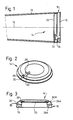
- the sleeve 10 shown in FIG. 1 is conical and in use serves as a carrier for a conical thread pack (not shown) which is wound in the form of a cross winding around the longitudinal axis 12 during the rotation of the sleeve 10. Only the sleeve end part with the larger diameter is shown in Fig. 1; it is attached to a sleeve-receiving part of a sleeve plate 14. Plate 14 is rotatably mounted on a "right" arm of a double-armed bobbin; both arm and arm are known and therefore not shown. The rotatable mounting of the "right” plate 14 enables the aforementioned rotation of the sleeve 10 (and the package thereon) about the longitudinal axis 12. A similar (not shown) "left" plate is rotatably mounted on the other arm of the bracket and takes the not shown smaller sleeve end part.
- the two arms of the bobbin case are mounted on a yoke (not shown) and can thus be rotated about a common yoke axis (not shown).
- a sleeve carried by the arms can thus initially be brought into contact with a friction roller (not shown) by rotating the bracket.
- the driven friction roller rotates about its own, stationary longitudinal axis and drives the sleeve about the sleeve axis 12 in order to form the package turns.
- the yoke rotates about the yoke axis to allow the sleeve to move away from the friction roller.
- the surface of the package remains in contact with the driving friction roller until the package is fully wound.
- the right plate 14 consists of a disk 16 with a conical surface 18 facing the sleeve.
- This conical part carries a continuation 20 which projects into the latter when the sleeve 10 is received, so that the end face of the sleeve lies against the conical surface 18 is coming.
- the left plate is similar.
- the sleeve axis 12 should coincide with the axes, not shown, of the bearing units carrying the sleeve plates. In practice, this is rare. It is in fact very difficult to precisely adjust the two arms of the winding bracket and their respective bearing units supporting the plates. It is even more difficult to ensure that the sleeve 10 is mounted on the same axis as the two plates, especially when the sleeve is no longer new and therefore already has damage on its end faces.
- the sleeve axis 12 should lie relative to the axes of the winding bracket and the friction roller, not shown, such that "line contact" between the sleeve 10 (or its packing) and the friction roller occurs. This result is difficult enough to achieve when winding a cylindrical package - when winding a conical package, the theoretical conditions are even less common.
- the plate 14 is provided with a driver 22, and the sleeve 10 has a notch 24 in the larger end part, which receives the driver.
- the simplest way is to provide the sleeve 10 with a (e.g. rectangular) cutout on the end face. The driver can protrude from the surface 18 and / or the extension 20 into the cutout.
- the driver and the cutout should be dimensioned such that the driver can be accommodated in the cutout without difficulty, but that there is contact between the driver and a longitudinal side of the cutout if there is a relative rotation between the plate 14 and the sleeve 10 takes place after the driver has been positioned in the cutout.
- the driver (and therefore the cutout) is preferably as thin as possible, provided that adequate strength and rigidity are guaranteed.
- the driver could obviously be firmly mounted on the plate or even be made in one piece with it. When inserting a sleeve into the bobbin case, it would then have to be checked each time whether the driver and the cutout match. Such attention is preferably not necessary; Various examples of a suitably designed plate and driver are now described with reference to FIGS. 2 to 10.
- the driver is in the form of a short pin 26, e.g. made of metal or plastic, shown, which tion in a radial drilling 28 in the plate 14 is movable in radial directions.
- the bore 28 bridges the connection between the conical surface 18 and the continuation 20.
- the pin is pressed radially outwards by an indicated resilient means 30 and is held in a first or standby position by positioning (e.g. a stop, not shown).
- this standby position FIG. 2
- the free end of the pin 26 projects out of the bore 28.
- the face of this free end forms an inclined surface 32, which is directed against the left arm and plate (see also Fig. 3).
- pin 26 contacts one of the long sides (axial sides) of the cutout, as well as the insufficient frictional connection for relative rotation leads between sleeve and plate.
- the direction of this rotation, and thus the long side touched, may vary depending on the circumstances. The rotation is stopped immediately by touching it.
- the outermost end of the pin should preferably not be pressed so far radially outward that it projects beyond the outer conical surface of the sleeve 10, because otherwise the pin comes into contact with the friction roller with each rotation of the sleeve 10 until a clearance between the sleeve and the roller has formed due to the structure of the pack.
- FIG. 3 shows a preferred embodiment of a plate according to FIG. 2.
- the plate 14 is hollowed out like a bowl, so that the surface 18 is located on a flange 15.
- This plate carries two pins 26, 26A, which are each in a bore 28, 28A in the flange 15.
- the axes of the bores 28, 28A form approximately an alignment line.
- each pin 26, 26A has a transverse bore through which a wire ring 33 leads.
- the ring is in when assembling the unit its circumference compressed and exerts a spring action on the pins 26, 26A to push them radially outward.
- the outward movement of the pins is limited by the fact that the ring itself comes to rest against the inner surface of the flange 15. So the ring works as both a resilient means and positioning stop.
- the ring gives in radially inwards when the pins are pressed inwards by the sleeve, but pushes a pin outwards again as soon as it is released by the sleeve, i.e. if it has been brought into line with the detail by the relative rotation. Since there are two pins 26, 26A, it takes at most almost half a turn to bring one of the two pins into line with the cutout.
- FIG. 4 and 4A show an example with a single driver in the form of a bolt 34, which can move back and forth in a radial groove 36 in the plate 14.
- the bolt is pressed radially outwards by a compression spring 38, and its end face is formed as an inclined surface 40.
- the mode of operation is the same as in the example in FIG. 2.
- Fig. 5 shows a double driver in the form of a wire spring with curved end portions 42, 44.
- the spring is shaped into an arc 41 which is received by the bowl-like cavity in the plate 14.
- Each end portion 42, 44 has a first curvature, so that these portions lie in a plane that is perpendicular to the aforementioned arc 41.
- everyone has End part 42, 44 a second curvature, so that the wire forms a small ring in the plane mentioned above.
- the extension 20 of the plate 14 has two slots 46, 48 through which an end portion 42, 44 protrudes.
- the principle of operation of this embodiment is basically the same as that of FIG. 3 and is therefore not further described.
- FIGS. 6 and 7 show another example with a flat spring, of which a central part 50 is secured in the central part of the plate 14 (not shown) and two end parts 52, 54 are each curved into a hook which lies over the extension 20. These end portions 52, 54 can each be pressed into a groove 53, 55 when the sleeve 10 covers both grooves. However, if a cutout in the sleeve matches a groove, the corresponding end section 52 or 54 jumps out again and engages in the cutout.
- the resilient means is not formed by a separate element, but by a piece 60 of the plate 14 itself.
- Two radial slots 62, 64 and a further connecting slot 66 in the plate flange form an elastically bendable "finger" 60 formed. The end part of this finger is enlarged radially outwards, the enlargement serving as a driver.
- FIGS. 10 and 10A are essentially the same, but the driver is formed by a pin 68 instead of an enlargement of the finger end part 70.
- FIGS. 9 and 9A the principle is similar to that for FIGS. 8 and 8A, with an elastic finger 72 and an enlargement 74 on the finger end part.
- the finger runs in the circumferential direction instead of in the radial direction.
- the notch is not necessarily in the form of a cutout and does not necessarily run to the front of the sleeve.
- the driver is not necessarily pressed radially outwards; it can also be mounted on a spring arm and touch the outer surface of the sleeve, being pressed radially inwards by the spring arm.
- the versions shown are much easier to implement.
Landscapes
- Braiding, Manufacturing Of Bobbin-Net Or Lace, And Manufacturing Of Nets By Knotting (AREA)
- Spinning Or Twisting Of Yarns (AREA)
- Winding Filamentary Materials (AREA)
Applications Claiming Priority (2)
| Application Number | Priority Date | Filing Date | Title |
|---|---|---|---|
| CH367586 | 1986-09-12 | ||
| CH3675/86 | 1986-09-12 |
Publications (2)
| Publication Number | Publication Date |
|---|---|
| EP0262443A1 true EP0262443A1 (fr) | 1988-04-06 |
| EP0262443B1 EP0262443B1 (fr) | 1991-03-27 |
Family
ID=4261094
Family Applications (1)
| Application Number | Title | Priority Date | Filing Date |
|---|---|---|---|
| EP87112848A Expired - Lifetime EP0262443B1 (fr) | 1986-09-12 | 1987-09-03 | Disque centreur de bobine |
Country Status (4)
| Country | Link |
|---|---|
| US (1) | US4848689A (fr) |
| EP (1) | EP0262443B1 (fr) |
| JP (1) | JPS6371074A (fr) |
| DE (1) | DE3768898D1 (fr) |
Cited By (3)
| Publication number | Priority date | Publication date | Assignee | Title |
|---|---|---|---|---|
| DE3829149C1 (en) * | 1988-08-27 | 1989-11-30 | Palitex Project-Company Gmbh, 4150 Krefeld, De | Winding apparatus for threads |
| DE10218993A1 (de) * | 2002-04-27 | 2003-11-06 | Schlafhorst & Co W | Hülsenteller für einen Spulenrahmen |
| EP2308787A3 (fr) * | 2009-10-08 | 2011-12-28 | Oerlikon Textile GmbH & Co. KG | Dispositif de bobinage |
Citations (7)
| Publication number | Priority date | Publication date | Assignee | Title |
|---|---|---|---|---|
| FR812270A (fr) * | 1935-10-29 | 1937-05-04 | Abbott Machine Co | Perfectionnements aux bobinoirs |
| US2776098A (en) * | 1953-07-03 | 1957-01-01 | Ind Rayon Corp | Tube holding assembly |
| FR1503330A (fr) * | 1965-12-07 | 1967-11-24 | Glanzstoff Ag | Dispositif d'entraînement pour des canettes à retordre avec étirage |
| US4327874A (en) * | 1980-11-28 | 1982-05-04 | Progressive Machine Company, Inc. | Spring loaded core adaptor |
| FR2504104A1 (fr) * | 1981-04-15 | 1982-10-22 | Asa Sa | Dispositif permettant le positionnement et le maintien d'un tube support de fil lors d'une operation de bobinage |
| US4359194A (en) * | 1980-03-24 | 1982-11-16 | Plastech Inc. | Two piece mandril for quick mounting and release of cones, used in textile industry |
| EP0088708A2 (fr) * | 1982-03-10 | 1983-09-14 | Société dite: ASA S.A. (société anonyme) | Dispositif permettant le positionnement et le maintien d'un tube support de fil lors d'une opération de bobinage |
Family Cites Families (7)
| Publication number | Priority date | Publication date | Assignee | Title |
|---|---|---|---|---|
| US1667916A (en) * | 1925-03-07 | 1928-05-01 | Ditto Inc | Spindle for gelatin rolls |
| US2250675A (en) * | 1940-04-20 | 1941-07-29 | Jr George B Markle | Arbor for spools or the like |
| AT269703B (de) * | 1965-12-01 | 1969-03-25 | Vyzk Ustav Bavlnarsky | Schwenkbarer zweiarmiger Spulenhalter für Textilmaschinen |
| US3430888A (en) * | 1967-07-27 | 1969-03-04 | Du Pont | End support for core |
| CH493406A (de) * | 1968-02-09 | 1970-07-15 | Elitex Zavody Textilniho | Vorrichtung zur Sicherung von Vorlagespulenhülsen auf einer drehbaren Nabe auf Textilmaschinen |
| DE2717461A1 (de) * | 1977-04-20 | 1978-11-02 | Eisbein Develop | Anordnung einer papierrolle in einem kopiergeraet |
| US4125229A (en) * | 1977-11-15 | 1978-11-14 | Macfield Texturing | Apparatus for restarting a broken thread or yarn strand during a winding process |
-
1987
- 1987-09-03 DE DE8787112848T patent/DE3768898D1/de not_active Expired - Lifetime
- 1987-09-03 EP EP87112848A patent/EP0262443B1/fr not_active Expired - Lifetime
- 1987-09-07 JP JP62222150A patent/JPS6371074A/ja active Pending
- 1987-09-10 US US07/094,763 patent/US4848689A/en not_active Expired - Fee Related
Patent Citations (7)
| Publication number | Priority date | Publication date | Assignee | Title |
|---|---|---|---|---|
| FR812270A (fr) * | 1935-10-29 | 1937-05-04 | Abbott Machine Co | Perfectionnements aux bobinoirs |
| US2776098A (en) * | 1953-07-03 | 1957-01-01 | Ind Rayon Corp | Tube holding assembly |
| FR1503330A (fr) * | 1965-12-07 | 1967-11-24 | Glanzstoff Ag | Dispositif d'entraînement pour des canettes à retordre avec étirage |
| US4359194A (en) * | 1980-03-24 | 1982-11-16 | Plastech Inc. | Two piece mandril for quick mounting and release of cones, used in textile industry |
| US4327874A (en) * | 1980-11-28 | 1982-05-04 | Progressive Machine Company, Inc. | Spring loaded core adaptor |
| FR2504104A1 (fr) * | 1981-04-15 | 1982-10-22 | Asa Sa | Dispositif permettant le positionnement et le maintien d'un tube support de fil lors d'une operation de bobinage |
| EP0088708A2 (fr) * | 1982-03-10 | 1983-09-14 | Société dite: ASA S.A. (société anonyme) | Dispositif permettant le positionnement et le maintien d'un tube support de fil lors d'une opération de bobinage |
Non-Patent Citations (1)
| Title |
|---|
| RESEARCH DISCLOSURE, Nr. 139, November 1975, Seite 26, Zusammenfassung 13932, Industrial Opportunities Ltd, Havant, Hampshire, GB; "Spring clip for yarn winding chuck" * |
Cited By (4)
| Publication number | Priority date | Publication date | Assignee | Title |
|---|---|---|---|---|
| DE3829149C1 (en) * | 1988-08-27 | 1989-11-30 | Palitex Project-Company Gmbh, 4150 Krefeld, De | Winding apparatus for threads |
| DE10218993A1 (de) * | 2002-04-27 | 2003-11-06 | Schlafhorst & Co W | Hülsenteller für einen Spulenrahmen |
| US6889933B2 (en) | 2002-04-27 | 2005-05-10 | W. Schlafhorst Ag & Co. | Tube plate for a creel |
| EP2308787A3 (fr) * | 2009-10-08 | 2011-12-28 | Oerlikon Textile GmbH & Co. KG | Dispositif de bobinage |
Also Published As
| Publication number | Publication date |
|---|---|
| US4848689A (en) | 1989-07-18 |
| DE3768898D1 (en) | 1991-05-02 |
| EP0262443B1 (fr) | 1991-03-27 |
| JPS6371074A (ja) | 1988-03-31 |
Similar Documents
| Publication | Publication Date | Title |
|---|---|---|
| DE3306322C2 (fr) | ||
| DE69119153T2 (de) | Bandeinfädelvorrichtung für Bandeinheit | |
| DE2405499C3 (de) | Bremsvorrichtung für einen Offen-End-Spinnrotor | |
| DE2322331B2 (de) | Kinokamera | |
| EP0262443B1 (fr) | Disque centreur de bobine | |
| DE2213147A1 (de) | Falschdrallvorrichtung | |
| DE69415108T2 (de) | Vorrichtung zum Trennen der gespeicherten Fadenwindungen bei Liefervorrichtungen für Webmaschinen oder dgl. | |
| DE2613089C3 (fr) | ||
| DE2612019A1 (de) | Anordnung zur selbsttaetigen loesbaren befestigung von spulen auf drehbaren naben | |
| DE3438179A1 (de) | Wickelvorrichtung | |
| DE935536C (de) | Streckwerkswalze fuer Spinnmaschinen-Streckwerke | |
| DE1510921C3 (de) | Spindel fur Textilmaschinen | |
| EP0350786A1 (fr) | Dispositif de bobinage | |
| CH623899A5 (en) | Safety clutch | |
| DE2454402A1 (de) | Huelsenhalter an textilmaschinen zum aufwickeln von garn oder faden | |
| DE68909263T2 (de) | Schussfadenspeicher für Webmaschinen. | |
| DE2427357A1 (de) | Fliehkraftkupplung | |
| DE2452939C2 (de) | Schwenkspindel | |
| DE2705529C3 (de) | Überwachungs- und Steuereinrichtung in einer eine Bremse aufweisenden Schnellverseilmaschine | |
| DE2406785C3 (de) | Uhr mit einer rohrförmigen Stundenzeigerwelle und einer koaxial in dieser angeordneten Minutenzeigerwelle | |
| DE828118C (de) | Bei Drehrichtungsumkehr einer Welle zu betaetigende Schalteinrichtung | |
| DE2142486C3 (de) | Liefervorrichtung | |
| DE3219483A1 (de) | Kupplung zum herstellen einer drehfesten verbindung | |
| DE3033047A1 (de) | Lagerung und antrieb fuer eine hohlspindel | |
| DE2721487A1 (de) | Vorrichtung zur kupplung eines zu einer naehmaschine gehoerenden elementes mit ihrer antriebswelle |
Legal Events
| Date | Code | Title | Description |
|---|---|---|---|
| PUAI | Public reference made under article 153(3) epc to a published international application that has entered the european phase |
Free format text: ORIGINAL CODE: 0009012 |
|
| AK | Designated contracting states |
Kind code of ref document: A1 Designated state(s): CH DE GB IT LI |
|
| 17P | Request for examination filed |
Effective date: 19880628 |
|
| 17Q | First examination report despatched |
Effective date: 19890720 |
|
| GRAA | (expected) grant |
Free format text: ORIGINAL CODE: 0009210 |
|
| AK | Designated contracting states |
Kind code of ref document: B1 Designated state(s): CH DE GB IT LI |
|
| PG25 | Lapsed in a contracting state [announced via postgrant information from national office to epo] |
Ref country code: IT Free format text: LAPSE BECAUSE OF FAILURE TO SUBMIT A TRANSLATION OF THE DESCRIPTION OR TO PAY THE FEE WITHIN THE PRE;WARNING: LAPSES OF ITALIAN PATENTS WITH EFFECTIVE DATE BEFORE 2007 MAY HAVE OCCURRED AT ANY TIME BEFORE 2007. THE CORRECT EFFECTIVE DATE MAY BE DIFFERENT FROM THE ONE RECORDED.SCRIBED TIME-LIMIT Effective date: 19910327 Ref country code: GB Effective date: 19910327 |
|
| REF | Corresponds to: |
Ref document number: 3768898 Country of ref document: DE Date of ref document: 19910502 |
|
| PGFP | Annual fee paid to national office [announced via postgrant information from national office to epo] |
Ref country code: GB Payment date: 19910808 Year of fee payment: 5 |
|
| PGFP | Annual fee paid to national office [announced via postgrant information from national office to epo] |
Ref country code: CH Payment date: 19910822 Year of fee payment: 5 |
|
| GBV | Gb: ep patent (uk) treated as always having been void in accordance with gb section 77(7)/1977 [no translation filed] | ||
| PLBE | No opposition filed within time limit |
Free format text: ORIGINAL CODE: 0009261 |
|
| STAA | Information on the status of an ep patent application or granted ep patent |
Free format text: STATUS: NO OPPOSITION FILED WITHIN TIME LIMIT |
|
| 26N | No opposition filed | ||
| PGFP | Annual fee paid to national office [announced via postgrant information from national office to epo] |
Ref country code: DE Payment date: 19920817 Year of fee payment: 6 |
|
| PG25 | Lapsed in a contracting state [announced via postgrant information from national office to epo] |
Ref country code: LI Effective date: 19920930 Ref country code: CH Effective date: 19920930 |
|
| REG | Reference to a national code |
Ref country code: CH Ref legal event code: PL |
|
| PG25 | Lapsed in a contracting state [announced via postgrant information from national office to epo] |
Ref country code: DE Effective date: 19940601 |