EP0262524B1 - Scintillateur chauffé - Google Patents
Scintillateur chauffé Download PDFInfo
- Publication number
- EP0262524B1 EP0262524B1 EP87113628A EP87113628A EP0262524B1 EP 0262524 B1 EP0262524 B1 EP 0262524B1 EP 87113628 A EP87113628 A EP 87113628A EP 87113628 A EP87113628 A EP 87113628A EP 0262524 B1 EP0262524 B1 EP 0262524B1
- Authority
- EP
- European Patent Office
- Prior art keywords
- camera
- crystal
- scintillation
- scintillator
- flashes
- Prior art date
- Legal status (The legal status is an assumption and is not a legal conclusion. Google has not performed a legal analysis and makes no representation as to the accuracy of the status listed.)
- Expired
Links
Images


Classifications
-
- G—PHYSICS
- G01—MEASURING; TESTING
- G01T—MEASUREMENT OF NUCLEAR OR X-RADIATION
- G01T1/00—Measuring X-radiation, gamma radiation, corpuscular radiation, or cosmic radiation
- G01T1/16—Measuring radiation intensity
- G01T1/161—Applications in the field of nuclear medicine, e.g. in vivo counting
- G01T1/164—Scintigraphy
- G01T1/1641—Static instruments for imaging the distribution of radioactivity in one or two dimensions using one or several scintillating elements; Radio-isotope cameras
- G01T1/1642—Static instruments for imaging the distribution of radioactivity in one or two dimensions using one or several scintillating elements; Radio-isotope cameras using a scintillation crystal and position sensing photodetector arrays, e.g. ANGER cameras
-
- G—PHYSICS
- G01—MEASURING; TESTING
- G01T—MEASUREMENT OF NUCLEAR OR X-RADIATION
- G01T1/00—Measuring X-radiation, gamma radiation, corpuscular radiation, or cosmic radiation
- G01T1/16—Measuring radiation intensity
- G01T1/161—Applications in the field of nuclear medicine, e.g. in vivo counting
- G01T1/164—Scintigraphy
- G01T1/1641—Static instruments for imaging the distribution of radioactivity in one or two dimensions using one or several scintillating elements; Radio-isotope cameras
- G01T1/1644—Static instruments for imaging the distribution of radioactivity in one or two dimensions using one or several scintillating elements; Radio-isotope cameras using an array of optically separate scintillation elements permitting direct location of scintillations
-
- G—PHYSICS
- G01—MEASURING; TESTING
- G01T—MEASUREMENT OF NUCLEAR OR X-RADIATION
- G01T1/00—Measuring X-radiation, gamma radiation, corpuscular radiation, or cosmic radiation
- G01T1/16—Measuring radiation intensity
- G01T1/20—Measuring radiation intensity with scintillation detectors
-
- G—PHYSICS
- G01—MEASURING; TESTING
- G01T—MEASUREMENT OF NUCLEAR OR X-RADIATION
- G01T1/00—Measuring X-radiation, gamma radiation, corpuscular radiation, or cosmic radiation
- G01T1/16—Measuring radiation intensity
- G01T1/20—Measuring radiation intensity with scintillation detectors
- G01T1/202—Measuring radiation intensity with scintillation detectors the detector being a crystal
Definitions
- the invention relates to scintillators, and more particularly relates to scintillation cameras which produce images of a patient under investigation. In its most advantageous application, the invention relates to scintillation cameras which produce tomographic images.
- a scintillation flash is associated with an X-Y position (referenced to the plane of the sensitive surface of the scintillator).
- a scintillator is not infinitesimally thin, and as a result, the apparent X-Y location of a scintillation flash may be, and usually is, different from the location of the scintillation event which generate the flash. Accordingly, to precisely locate the situs (and thus the true X-Y position) of a scintillation event, both the apparent X-Y position of the resulting flash and the depth of the event within the scintillator must be known.
- the French Patent Application 2 543 691 discloses a scintillation detector with a single crystal. A temperature gradient is created across that crystal and thereby a spatial resolution in the direction of the gradient is obtained.
- One object of the invention is to provide a scintillator system which is so designed that the depth of a scintillation event within the scintillator can be determined.
- a further object is to provide a scintillation camera system which utilizes the depth so determined in production of a planar or tomographic image.
- Another object is, in general, to improve on known devices and techniques.
- the invention proceeds from a realization that heated scintillators have advantageous characteristics.
- a heated scintillator produces scintillation flashes which decay faster than do flashes produced by a scintillator at room temperature, and the effective count rate of a scintillation camera system can be increased merely by heating the scintillator in an otherwise conventional scintillation camera head because the faster flash decay reduces pulse pile-ups.
- the invention also proceeds from a realization that the decay time of scintillation flashes varies with the temperature of the scintillator at the site of the event which generated the flash. More specifically, a scintillation flash from an event which takes place at a site held at 20 ° C decays more slowly than does a scintillation flash from an event which takes place at a site held at 80°C.
- a temperature gradient is established across the depth of the scintillator i.e. normal to its input and output surfaces within a center domain of the scintillator.
- the decay time of detected scintillation flashes is monitored. This may advantageously be done by a) differentiating the normalized output from the photodetectors which are used to detect the flashes from scintillation events within the scintillator or b) timing the decay of the flash.
- the decay time of each scintillation flash is related to the temperature of the scintillator at the site of the coresponding scintillation event. Since this temperature is in turn related to the depth of the site within the scintillator, it follows that the measurement of decay time of a detected scintillation flash represents the depth of the site of the corresponding scintillation event within the scintillator. Hence, the depth of the event within the scintillator can be determined for each scintillation event which generates a flash. This additional information can be taken into account in production of the finished image (or, if no image is formed, in interpretation of the data generated by the event).
- a determination of the depth of a scintillation event within a scintillator is also useful because this permits the energy resolution of a scintillation camera system to be improved.
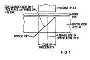
- Fig. 1 illustrates the problems in spatial resolution which arise where a scintillator is relatively thick and/or where incident radiation strikes the scintillator at other than substantially right angles.
- the information from the photodetector includes information about the depth of the scintillationevent
- a more precise location of that event within the zone is made possible. It will be clear from Fig. 1 that where the depth of the event is known, the location of the site of the event can be precisely determined.
- Fig. 2 is illustrative; it may be but need not be typical.
- the data in Fig. 2 was derived from the normalized electrical output of a phototube which was used to measure the intensity of scintillation flashes occuring in a Csl(Na) scintillator. As is shown there, a scintillation flash produced in a scintillator which is at 20 ° C decays more slowly than does a flash produced in a scintillator at 80 ° C.
- the instantaneous rate of decay of the scintillation flash and therefore the temperature of the site at which the corresponding scintillation event occurs can be determined.
- the flash may be timed.
- a temperature gradient is established normal to the input and output surfaces of a scintillation crystal so that the depth of a scintillation event within the scintillator can be determined.
- cooling effects at the periphery of the scintillator will prevent the gradient from being normal to these surfaces except in a center domain of the scintillator. Outside this center domain, the information produced by this preferred embodiment is less useful, and may be ignored.
- a preferred embodiment of apparatus for achieving this is schematically illustrated in Fig. 3.
- a scintillation camera system (otherwise not shown, but including such standard features as a computer, a CRT display, and a keyboard) includes a scintillation crystal 2.
- the crystal 2 is any of the scintillation materials used in nuclear medicine, advantageously BGO, Nal(TI) or Csl(Na).
- the crystal 2 is contained within a housing 4 of, e.g. aluminum and is surrounded on its input surface and its peripheral surface by an air gap 10. Inside the housing is a reflector 8 of Teflon or e.g. MgO paint, to reflect scintillation light back towards the crystal 2.
- a heater 6 On the input side of the scintillator 2, on the outside of the housing 4, is located a heater 6 which is advantageously made of a fiberglass heat tape.
- the heater 6 is located on the outside of the housing 4, so the heater 6 can be replaced if necessary, but the heater 6 may be located inside the housing 4 if desired.
- the heater 6 is advantageously spaced from the crystal 2 to avoid subjecting the crystal 2 to thermal shock when the heater 6 is energized through wires 12.
- Fig. 3 is not to scale, and various parts have been enlarged for clarity. Because the spatial resolution of a scintillation camera degrades as the spacing between the patient (not shown) and scintillation crystal increases, it is advantageous to make the heater 6 and housing 4 as thin as is feasible. In this connection, it is preferable to make the heater 6 of a multiplicity of fine conductors (not shown), rather than as a smaller number of larger conductors. This is to minimize the likelihood that the conductors will be imaged during use.
- the crystal 2 is fixed to a substrate 14 by a bonding material 16, and the housing 4 is secured to the substrate 14 by a hermetic seal 18.
- the material 16 is a two-part RTV (room-temperature vulcanizing) silicone rubber, and the substrate 14 is advantageously Pyrex glass, but these materials are not part of the invention.
- the apparatus shown in Fig. 3 is, with the exception of the heater 6, entirely conventional.
- a light pipe 20 is attached to the substrate 14 by a bonding agent 22, and a plurality of photodetectors 24 (in this example, these are phototubes but they could also be avalanche photodiodes) are mounted to the light pipe 20 through a bonding agent 26. This places the photodetectors 24 in optical communication with the output surface of the crystal 2.
- the bonding agents 22 and 26 are advantageously silicone grease, but this is conventional and it will be understood that the structure by which the phototubes 24 are placed in optical communication with the output surface of the scintillation crystal 2 is not part of this invention.
- Heat from the heater 6 is supplied to the input surface of the scintillation crystal 2 and the input surface of the crystal 2 is kept at a predetermined temperature which in this example is 80°C. (This temperature was chosen because it can be implemented in a conventional scintillation camera head as manufactured by Siemens Gammasonics, Inc. without requiring any substantial redesign work, but it is not necessary to the invention.) Most of the heat leaves the crystal 2 through its output surface and is radiated to the outside through the light pipe 20 and the aluminum housing 4.
- the materials and thicknesses of the various components should be such that a temperature difference of approximately 60°C exists between the input and output surfaces of the crystal 2 and varies (approximately linearly) between them.
- the output signal representing the flash is analyzed to determine the rate at which the flash decays.
- One preferred embodiment of carrying out this analysis comprises a differentiation and normalizing circuit which produces a normalized output representative of the slope of the pulse immediately adjacent its peak.
- a specific method is to normalize the pulse height of the output signal and then to differentiate it with respect to time.
- Another preferred method is to time the duration of the flash or of the decay of the flash. The appropriate operations are carried out by a circuit 28.
- Circuit 28 produces an intermediate result which, when input to an appropriate look-up table 30 or other memory, produces output representing the depth of the scintillation event within the crystal 2. This information is then routed to the reconstruction computer (not shown) which uses it, together with information about the location and energy of the event, to reconstruct the final image.
- output signal does not refer to the direct output of each of the photodetectors 24. Normally, a flash is detected by more than one photodetector 24 and the outputs of all affected photodetectors 24 are combined to produce a composite signal (which itself contains composite location and intensity information characterizing the event).
- output signal refers to the electrical signal which contains the intensity information.
- the effective count rate of the scintillation camera system is increased. This is because pulse pile-up - the overlapping of two successive scintillation flashes - is less likely to occur when the flashes decay more rapidly. Since the electronics of a scintillation camera system is conventionally set up to reject counts from pulse pile-ups, the effective count rate of the system is increased because the likelihood of pile-ups is diminished.
Landscapes
- Physics & Mathematics (AREA)
- Health & Medical Sciences (AREA)
- Spectroscopy & Molecular Physics (AREA)
- Life Sciences & Earth Sciences (AREA)
- Molecular Biology (AREA)
- High Energy & Nuclear Physics (AREA)
- General Physics & Mathematics (AREA)
- Nuclear Medicine, Radiotherapy & Molecular Imaging (AREA)
- Optics & Photonics (AREA)
- Biomedical Technology (AREA)
- Medical Informatics (AREA)
- General Health & Medical Sciences (AREA)
- Engineering & Computer Science (AREA)
- Chemical & Material Sciences (AREA)
- Crystallography & Structural Chemistry (AREA)
- Measurement Of Radiation (AREA)
- Nuclear Medicine (AREA)
Claims (14)
Applications Claiming Priority (2)
| Application Number | Priority Date | Filing Date | Title |
|---|---|---|---|
| US06/913,798 US4810885A (en) | 1986-09-30 | 1986-09-30 | Heated scintillator |
| US913798 | 1986-09-30 |
Publications (2)
| Publication Number | Publication Date |
|---|---|
| EP0262524A1 EP0262524A1 (fr) | 1988-04-06 |
| EP0262524B1 true EP0262524B1 (fr) | 1990-07-11 |
Family
ID=25433585
Family Applications (1)
| Application Number | Title | Priority Date | Filing Date |
|---|---|---|---|
| EP87113628A Expired EP0262524B1 (fr) | 1986-09-30 | 1987-09-17 | Scintillateur chauffé |
Country Status (4)
| Country | Link |
|---|---|
| US (1) | US4810885A (fr) |
| EP (1) | EP0262524B1 (fr) |
| JP (1) | JPS63108290A (fr) |
| DE (1) | DE3763640D1 (fr) |
Families Citing this family (7)
| Publication number | Priority date | Publication date | Assignee | Title |
|---|---|---|---|---|
| US4879465A (en) * | 1986-09-30 | 1989-11-07 | Siemens Gammasonics, Inc. | Detector module for scintillation cameras |
| GB2387435B (en) * | 2000-06-15 | 2005-01-05 | Schlumberger Technology Corp | Nuclear detector for multiphase fluid sensing |
| US7684545B2 (en) * | 2007-10-30 | 2010-03-23 | Rigaku Innovative Technologies, Inc. | X-ray window and resistive heater |
| US8987670B2 (en) | 2008-10-09 | 2015-03-24 | Schlumberger Technology Corporation | Thermally-protected scintillation detector |
| JP5473835B2 (ja) * | 2010-08-31 | 2014-04-16 | 富士フイルム株式会社 | 放射線検出器、放射線画像撮影装置及び放射線検出器の製造方法 |
| GB201114151D0 (en) | 2011-08-17 | 2011-10-05 | Johnson Matthey Plc | Density and level measurement apparatus |
| CN110646835A (zh) * | 2019-10-31 | 2020-01-03 | 中国工程物理研究院流体物理研究所 | 一种缩短lyso晶体闪烁衰减时间的实验装置及其实验方法 |
Family Cites Families (10)
| Publication number | Priority date | Publication date | Assignee | Title |
|---|---|---|---|---|
| US3904530A (en) * | 1971-11-15 | 1975-09-09 | Picker Corp | Scintillation camera |
| JPS54144179A (en) * | 1978-05-01 | 1979-11-10 | Le G Yuniberushitetsuto Imeeni | Analyzer |
| US4455616A (en) * | 1979-07-09 | 1984-06-19 | Elscint, Ltd. | Fast gamma camera |
| US4303860A (en) * | 1979-07-30 | 1981-12-01 | American Science And Engineering, Inc. | High resolution radiation detector |
| US4292538A (en) * | 1979-08-08 | 1981-09-29 | Technicare Corporation | Shaped detector |
| US4398092A (en) * | 1979-08-08 | 1983-08-09 | Technicare Corporation | Shaped detector |
| US4489236A (en) * | 1981-11-18 | 1984-12-18 | Fairchild Weston Systems, Inc. | Method for calibrating scintillation crystal |
| US4511799A (en) * | 1982-12-10 | 1985-04-16 | American Science And Engineering, Inc. | Dual energy imaging |
| FR2543691A1 (fr) * | 1983-03-31 | 1984-10-05 | Sendyk Andrzej | Detecteur pour la detection de position d'une radiation ionisante |
| JPS61155886A (ja) * | 1984-12-28 | 1986-07-15 | Toshiba Corp | 放射線検出器 |
-
1986
- 1986-09-30 US US06/913,798 patent/US4810885A/en not_active Expired - Fee Related
-
1987
- 1987-09-17 EP EP87113628A patent/EP0262524B1/fr not_active Expired
- 1987-09-17 DE DE8787113628T patent/DE3763640D1/de not_active Expired - Lifetime
- 1987-09-28 JP JP62245739A patent/JPS63108290A/ja active Pending
Also Published As
| Publication number | Publication date |
|---|---|
| EP0262524A1 (fr) | 1988-04-06 |
| US4810885A (en) | 1989-03-07 |
| DE3763640D1 (de) | 1990-08-16 |
| JPS63108290A (ja) | 1988-05-13 |
Similar Documents
| Publication | Publication Date | Title |
|---|---|---|
| US4598202A (en) | Nuclear and pressure sensitive line/perimeter detection system | |
| US3911280A (en) | Method of measuring a profile of the density of charged particles in a particle beam | |
| JPH0214666B2 (fr) | ||
| JPH06508926A (ja) | 中性子ならびにXないしγ光子の選択的同時検出プロセスおよび検出装置 | |
| EP0199118A1 (fr) | Méthode et dispositif pour codage tridimensionnel | |
| US5264702A (en) | On-line tritium production monitor | |
| US4843245A (en) | Scintillation detector for tomographs | |
| US4463263A (en) | Positron-annihilation-radiation transmission gauge | |
| US4005292A (en) | Mass counting of radioactivity samples | |
| CA2236295A1 (fr) | Detecteur multiphotonique a bruit de fond ultra-bas | |
| US6124595A (en) | Gamma ray imaging detector with three dimensional event positioning and method of calculation | |
| EP0262524B1 (fr) | Scintillateur chauffé | |
| US5055691A (en) | Radiation meter | |
| EP3674752B1 (fr) | Système de détecteur et dispositif d'imagerie par rayonnements | |
| WO1981003698A1 (fr) | Procede et dispositif permettant le controle d'un mouvement | |
| Sudarkin et al. | High-energy radiation visualizer (HERV): A new system for imaging in X-ray and gamma-ray emission regions | |
| US3914602A (en) | Plutonium monitor | |
| US3609361A (en) | Method and apparatus for external standardization of liquid scintillation samples | |
| US4879465A (en) | Detector module for scintillation cameras | |
| AU637710B2 (en) | Density-moisture measuring system | |
| JP2851319B2 (ja) | 放射線計測装置の放射線検出部 | |
| US4617167A (en) | Underwater radiation detector | |
| JPH09101371A (ja) | ガンマ線検出方法及び検出装置 | |
| JPS6249282A (ja) | 放射能濃度モニタ | |
| JPH07311270A (ja) | 放射線検出器 |
Legal Events
| Date | Code | Title | Description |
|---|---|---|---|
| PUAI | Public reference made under article 153(3) epc to a published international application that has entered the european phase |
Free format text: ORIGINAL CODE: 0009012 |
|
| AK | Designated contracting states |
Kind code of ref document: A1 Designated state(s): DE FR GB NL |
|
| 17P | Request for examination filed |
Effective date: 19880425 |
|
| 17Q | First examination report despatched |
Effective date: 19890309 |
|
| GRAA | (expected) grant |
Free format text: ORIGINAL CODE: 0009210 |
|
| AK | Designated contracting states |
Kind code of ref document: B1 Designated state(s): DE FR GB NL |
|
| REF | Corresponds to: |
Ref document number: 3763640 Country of ref document: DE Date of ref document: 19900816 |
|
| ET | Fr: translation filed | ||
| PLBE | No opposition filed within time limit |
Free format text: ORIGINAL CODE: 0009261 |
|
| STAA | Information on the status of an ep patent application or granted ep patent |
Free format text: STATUS: NO OPPOSITION FILED WITHIN TIME LIMIT |
|
| 26N | No opposition filed | ||
| PGFP | Annual fee paid to national office [announced via postgrant information from national office to epo] |
Ref country code: DE Payment date: 19911127 Year of fee payment: 5 |
|
| PGFP | Annual fee paid to national office [announced via postgrant information from national office to epo] |
Ref country code: GB Payment date: 19920820 Year of fee payment: 6 |
|
| PGFP | Annual fee paid to national office [announced via postgrant information from national office to epo] |
Ref country code: NL Payment date: 19920930 Year of fee payment: 6 |
|
| PG25 | Lapsed in a contracting state [announced via postgrant information from national office to epo] |
Ref country code: DE Effective date: 19930602 |
|
| PG25 | Lapsed in a contracting state [announced via postgrant information from national office to epo] |
Ref country code: GB Effective date: 19930917 |
|
| PGFP | Annual fee paid to national office [announced via postgrant information from national office to epo] |
Ref country code: FR Payment date: 19930917 Year of fee payment: 7 |
|
| PG25 | Lapsed in a contracting state [announced via postgrant information from national office to epo] |
Ref country code: NL Effective date: 19940401 |
|
| GBPC | Gb: european patent ceased through non-payment of renewal fee |
Effective date: 19930917 |
|
| NLV4 | Nl: lapsed or anulled due to non-payment of the annual fee | ||
| PG25 | Lapsed in a contracting state [announced via postgrant information from national office to epo] |
Ref country code: FR Effective date: 19950531 |
|
| REG | Reference to a national code |
Ref country code: FR Ref legal event code: ST |