EP0262634A1 - Appareil pour la gravure de cylindres hélio et de formes d'impression similaires - Google Patents
Appareil pour la gravure de cylindres hélio et de formes d'impression similaires Download PDFInfo
- Publication number
- EP0262634A1 EP0262634A1 EP87114117A EP87114117A EP0262634A1 EP 0262634 A1 EP0262634 A1 EP 0262634A1 EP 87114117 A EP87114117 A EP 87114117A EP 87114117 A EP87114117 A EP 87114117A EP 0262634 A1 EP0262634 A1 EP 0262634A1
- Authority
- EP
- European Patent Office
- Prior art keywords
- holder
- scanning
- scanning element
- engraving
- damping arrangement
- Prior art date
- Legal status (The legal status is an assumption and is not a legal conclusion. Google has not performed a legal analysis and makes no representation as to the accuracy of the status listed.)
- Granted
Links
Images


Classifications
-
- B—PERFORMING OPERATIONS; TRANSPORTING
- B44—DECORATIVE ARTS
- B44B—MACHINES, APPARATUS OR TOOLS FOR ARTISTIC WORK, e.g. FOR SCULPTURING, GUILLOCHING, CARVING, BRANDING, INLAYING
- B44B3/00—Artists' machines or apparatus equipped with tools or work holders moving or able to be controlled substantially two-dimensionally for carving, engraving, or guilloching shallow ornamenting or markings
- B44B3/06—Accessories, e.g. tool or work holders
- B44B3/061—Tool heads
-
- B—PERFORMING OPERATIONS; TRANSPORTING
- B41—PRINTING; LINING MACHINES; TYPEWRITERS; STAMPS
- B41C—PROCESSES FOR THE MANUFACTURE OR REPRODUCTION OF PRINTING SURFACES
- B41C1/00—Forme preparation
- B41C1/02—Engraving; Heads therefor
- B41C1/04—Engraving; Heads therefor using heads controlled by an electric information signal
-
- Y—GENERAL TAGGING OF NEW TECHNOLOGICAL DEVELOPMENTS; GENERAL TAGGING OF CROSS-SECTIONAL TECHNOLOGIES SPANNING OVER SEVERAL SECTIONS OF THE IPC; TECHNICAL SUBJECTS COVERED BY FORMER USPC CROSS-REFERENCE ART COLLECTIONS [XRACs] AND DIGESTS
- Y10—TECHNICAL SUBJECTS COVERED BY FORMER USPC
- Y10T—TECHNICAL SUBJECTS COVERED BY FORMER US CLASSIFICATION
- Y10T409/00—Gear cutting, milling, or planing
- Y10T409/30—Milling
- Y10T409/30084—Milling with regulation of operation by templet, card, or other replaceable information supply
- Y10T409/301176—Reproducing means
- Y10T409/301624—Duplicating means
- Y10T409/30168—Duplicating means with means for operation without manual intervention
- Y10T409/302072—Duplicating means with means for operation without manual intervention including tracer adapted to trigger fluid energy
- Y10T409/302128—Duplicating means with means for operation without manual intervention including tracer adapted to trigger fluid energy to actuate fluid driven work or tool moving means
- Y10T409/302184—Duplicating means with means for operation without manual intervention including tracer adapted to trigger fluid energy to actuate fluid driven work or tool moving means including cutter and tracer fixed to move laterally together
Definitions
- the present invention relates to a device for engraving rotogravure cylinders and similar printing forms according to the preamble of claim 1.
- the up and down movement of the engraving stylus is generated by a control signal which is derived from an image signal obtained by scanning a template.
- a raster frequency which defines the raster width is superimposed on this control signal.
- the continuously oscillating engraving stylus sinks into the surface of the gravure cylinder.
- the engraving stylus cuts out raster cups that vary in depth and surface size according to the tonal value.
- the present invention has for its object to provide an engraving device of the type mentioned, with the disruptive effects of unevenness in the surface of the printing cylinder on the engraving of the same can be largely avoided in the simplest possible way.
- the present invention is based on the finding that the scanning element, which is in contact with the printing cylinder and follows the unevenness of its surface with a certain pressure, is set into vibrations which are transmitted to the holder, which is thereby excited to produce natural vibrations.
- the vibrations of the holder are in turn transferred to the engraving tool, which influences its controlled oscillation movement. This in turn affects the cutting process and the design of the grid cells.
- By providing a damping arrangement which acts directly on the scanning element or on an element fastened to it movements of the scanning element caused by unevenness in the pressure cylinder are largely damped. This effectively prevents the holder and thus also the engraving tool from vibrating in a simple manner, which would have a disadvantageous effect on the engraving process.
- an engraving device for engraving printing cylinders in which the engraving stylus is moved in translation by excitation of electromagnets by means of control pulses.
- the engraving stylus is supported at its rear end on compression springs, which also determine the pressure with which the engraving stylus is pressed against the pressure cylinder when the electromagnet is excited.
- the abutting elements on the outer surface of the pressure cylinder are fastened to a holder without the interposition of a damping arrangement, in which the engraving stylus and the electromagnets are also mounted.
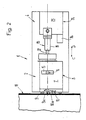
- the cliché 1 shown in FIGS. 1-3 has a plurality of engraving heads 2 of known construction, of which only one is shown in the figures.
- the engraving head 2 is fastened on a carriage 4 which can be moved in the direction of the arrows C, D.
- a clamping device 5 which is only shown schematically in FIG. 3.
- the holder 3 consists of a lower part 6 and an upper part 7.
- the lower part 6 is attached to the carriage 4 and connected to the upper part 7 via leaf springs 8 (FIG. 1).
- the upper holder part 7 can thus be fixed by a leaf spring 8 and pivot the axis extending at right angles to the direction of movement C, D of the carriage 4 relative to the lower holder part 6, as is known per se.
- An elongated scanning element 9 is held in the upper holder part 7, the tip 9a of which protrudes.
- an engraving stylus 10 is mounted in the holder part 7, the cutting tip of which is designated 10a.
- the engraving stylus 10 performs an up and down movement in a known manner, not shown.
- the upper part 7 of the holder 3 is moved by moving the carriage 4 in the direction of arrow C and tilting it about the axis defined by the leaf springs 8 against the gravure cylinder 11 to be engraved, until the scanning element 9 with its tip 9a with a certain pressure abuts the surface of the impression cylinder 11.
- the scanning element 9 passes through a through hole 12 formed in the holder part 7.
- this through hole 12 there is a clamping sleeve 13 surrounding the shaft 9b of the scanning element 9, which tapers conically towards the tip 9a of the scanning element 9.
- the through hole 12 has a corresponding conical taper.
- the metallic clamping sleeve 13 is provided with an internal thread, not shown in FIG.
- a fine thread into which an external thread, also not shown in FIG. 1, engages, which is formed on the shaft 9b of the scanning element 9.
- a clamping sleeve 14 which is provided with an external thread, also not shown in FIG. 1, which cooperates with a thread in the interior of the through bore 12.
- the clamping sleeve 14 is by means of a Tool rotated, which can be inserted through an opening 15 in the holder part 7 (Fig. 2).
- the scanning element 9 is connected at its rear end to a handwheel or adjusting knob 16, by means of which the scanning element 9 can be rotated and screwed into the clamping sleeve 13 to a greater or lesser extent.
- a scale 17 interacts with the handwheel 16 and is attached to the upper holder part 7.
- a damping element 18 which acts directly on the scanning element 9 or the handwheel 16 is provided, which has a cylindrical housing 19 in which a piston 20 (FIG. 1) is displaceably guided.
- This piston 20 is supported on a compression spring 21 accommodated in the housing 19, as can be seen in FIG. 1.
- a plunger 22 is connected to the piston 20 and engages with its free end in a recess 23 in the handwheel 16. It is of course also conceivable not to connect the plunger 22 directly as shown, but via an intermediate piece to the scanning element 9 or the handwheel 16. The plunger 22 is in loose engagement with the recess 23 so that a certain relative movement between the plunger 22 and the scanning element 9 or the handwheel 16 is possible.
- the damping element 18 is attached to a holder 24 which is separate from the holder 3 for the scanning element 9 and the engraving stylus 10. However, the holder 24 is also fastened on the carriage 4 and can be moved together with the holder 3 in the direction of the arrow C, D.
- the clamping sleeve 13 can also be designed differently than as shown in FIG. 1.
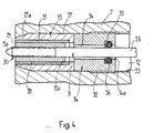
- a possible variant is shown in Fig. 4 and in DE-PS 36 19 320.
- the sleeve 13 shown in FIG. 4 and having a through opening 13a consists of two interconnected parts 27 and 28.
- the outer sleeve part 27 is conically tapered at its end 27a facing the tip 9a of the scanning element 9.
- the inner sleeve part 28 is provided with an internal thread 29, which is a fine thread, into which the shaft 9b of the scanning element 9 carrying an external thread 30 is screwed.
- a sleeve-like damping element 31 is arranged between the two sleeve parts 27 and 28, which on the one hand connects the two sleeve parts 27 and 28 to one another and on the other hand separates them.
- This damping element 31 consists of an elastically deformable, energy-absorbing material, preferably an elastomer.
- Butyl rubber has proven to be a particularly suitable material. However, it is entirely possible to use natural or nitrile rubber or other types of rubber or rubber. Basically, any material is suitable for the damping element 31 which, on the one hand, completely or at least for the most part or completely suppresses vibration transmission from the scanning element 9 or from the sleeve part 28 connected to it to the outer sleeve part 27 and thus the holder 3 or its upper part 7 prevents and which on the other hand creates a sufficiently rigid connection between the sleeve parts 27, 28, so that a firm and precise guidance of the scanning element 9 in the clamping sleeve 13 is ensured.
- the clamping sleeve 14 arranged coaxially to the clamping sleeve 13 in the through bore 12 in the upper holder part 7 is also included provided with an external thread 32. The latter is in engagement with a thread 33 provided on the inside of the through hole 12.
- the diameter of the through hole 14a in the clamping sleeve 14 is somewhat larger than the outside diameter of the shaft 9b of the scanning element 9. Between the latter and the wall of the through hole 14a, an intermediate space 34 of annular cross section is thus formed.
- the clamping sleeve 14 is provided on its inside with a circumferential groove 35 which is open towards the through hole 14a.
- a damping element 36 in the form of an O-ring is arranged in this groove 35 on the shaft 9b of the scanning element 9. This damping member 36 serves to guide the scanning member 9 on the one hand and on the other hand to suppress or prevent the transmission of vibrations of the scanning member 9 to the clamping sleeve 14 and thus the holder 3 or its upper part 7.
- the scanning element 9 is decoupled via the damping element 31 and the damping element 36 from the upper holder part 7 and thus also from the engraving stylus 10.
- vibrations of the scanning element 9 are caused by the damping elements 31 and 36 on it prevented from being transferred to the outer sleeve part 27 or the clamping sleeve 14.
- This configuration of the mounting of the scanning element 9 thus additionally contributes to the described damping of the movements of the scanning element 9 by the damping element 18, so that the inevitable movements of the scanning element 9 in the direction of its longitudinal axis 9 'cannot have a disruptive effect on the engraving of the grid cells.
- the damping element 18 could also be designed such that the piston 20 is acted upon on both sides by spring elements or a pressure medium.
- the damping element 19 could also move the scanning element 9 towards the pressure cylinder 11, i.e. in the direction of arrow E, have a dampening effect.
- the plunger 22 could, for example, be firmly connected to the handwheel 16.
Landscapes
- Engineering & Computer Science (AREA)
- Manufacturing & Machinery (AREA)
- Manufacture Or Reproduction Of Printing Formes (AREA)
Applications Claiming Priority (2)
| Application Number | Priority Date | Filing Date | Title |
|---|---|---|---|
| CH3940/86 | 1986-10-02 | ||
| CH3940/86A CH672458A5 (fr) | 1986-10-02 | 1986-10-02 |
Publications (2)
| Publication Number | Publication Date |
|---|---|
| EP0262634A1 true EP0262634A1 (fr) | 1988-04-06 |
| EP0262634B1 EP0262634B1 (fr) | 1991-07-03 |
Family
ID=4266756
Family Applications (1)
| Application Number | Title | Priority Date | Filing Date |
|---|---|---|---|
| EP87114117A Expired - Lifetime EP0262634B1 (fr) | 1986-10-02 | 1987-09-27 | Appareil pour la gravure de cylindres hélio et de formes d'impression similaires |
Country Status (4)
| Country | Link |
|---|---|
| US (1) | US4830552A (fr) |
| EP (1) | EP0262634B1 (fr) |
| CH (1) | CH672458A5 (fr) |
| DE (1) | DE3771155D1 (fr) |
Cited By (2)
| Publication number | Priority date | Publication date | Assignee | Title |
|---|---|---|---|---|
| EP0741008A3 (fr) * | 1995-05-02 | 1998-05-13 | MDC Max Dätwyler Bleienbach AG | Appareil pour graver des cylindres d'impression |
| US5816756A (en) * | 1995-05-02 | 1998-10-06 | Mdc Max Datwyler Bleienbach Ag | Device for engraving intaglio cylinders |
Families Citing this family (11)
| Publication number | Priority date | Publication date | Assignee | Title |
|---|---|---|---|---|
| US5663803A (en) * | 1993-02-25 | 1997-09-02 | Ohio Electronic Engravers, Inc. | Engraving method and apparatus for engraving areas using a shaping signal |
| US5454306A (en) * | 1993-07-12 | 1995-10-03 | Ohio Electric Engravers, Inc. | Engraving head platform |
| US5675420A (en) | 1995-01-23 | 1997-10-07 | Ohio Electronic Engravers, Inc. | Intaglio engraving method and apparatus |
| US6025921A (en) * | 1995-01-23 | 2000-02-15 | Ohio Electronics Engravers, Inc. | Method and apparatus for engraving a mixed pattern |
| US5555473A (en) * | 1995-02-21 | 1996-09-10 | Ohio Electronic Engravers, Inc. | Engraving system and method for helical or circumferential engraving |
| JPH0929923A (ja) * | 1995-07-18 | 1997-02-04 | Dainippon Screen Mfg Co Ltd | グラビア彫刻機の潤滑剤塗布装置 |
| US5652659A (en) * | 1995-10-09 | 1997-07-29 | Ohio Electronic Engravers, Inc. | System and method for measuring run-out and other characteristics of a workpiece mounted on an engraver |
| DE19624131A1 (de) * | 1996-06-17 | 1997-12-18 | Giesecke & Devrient Gmbh | Verfahren zur Herstellung von Prägeplatten |
| FR2849549B1 (fr) * | 2002-12-27 | 2005-10-07 | Gravograph Ind Internat | Moteur electrique a axe creux et machine a graver le mettant en oeuvre |
| CN106032086B (zh) * | 2015-03-13 | 2019-09-24 | 上海运申制版模具有限公司 | 一种减少雕刻横纹的电雕机 |
| CN107175944A (zh) * | 2017-04-24 | 2017-09-19 | 太仓丽盛制版有限公司 | 一种电子雕刻凹印辊消除横纹的加工方法 |
Citations (7)
| Publication number | Priority date | Publication date | Assignee | Title |
|---|---|---|---|---|
| BE542897A (fr) * | ||||
| GB458112A (en) * | 1935-06-13 | 1936-12-14 | John Willey Dalton | Improvements in and relating to engraving and cutting tools and means of actuating the same |
| US3339279A (en) * | 1964-07-17 | 1967-09-05 | Robert H Sovar | Hollow engraving point and holder for engraving coated transparent sheets |
| DE2307095A1 (de) * | 1973-02-14 | 1974-08-22 | Jens Scheel | Spanabhebende herstellung von druckformen und druckwalzen aus weichen und harten materialien, mit hilfsfraesspindel geringen gewichtes |
| DE2336089A1 (de) * | 1973-07-16 | 1975-02-06 | Hell Rudolf Dr Ing Gmbh | Aufzeichnungssystem, insbesondere graviersystem fuer eine druckform-graviermaschine |
| GB1542556A (en) * | 1976-09-22 | 1979-03-21 | Us Army | Peel coat cutter |
| DE3619320C1 (de) * | 1986-06-09 | 1987-03-05 | Daetwyler Ag | Gravierkopf fuer ein Geraet zum Gravieren von Tiefdruckzylindern und aehnlichen Druckformen |
Family Cites Families (4)
| Publication number | Priority date | Publication date | Assignee | Title |
|---|---|---|---|---|
| US711273A (en) * | 1901-09-03 | 1902-10-14 | Marinier Navoit Et Jeanson Soc | Engraving-machine. |
| US1695617A (en) * | 1925-07-27 | 1928-12-18 | Teissere Albert | Process of and apparatus for engraving printing cylinders |
| GB552415A (en) * | 1941-01-08 | 1943-04-07 | Niles Bement Pond Co | Improvements in and relating to electric controls for machine tools |
| SU996173A1 (ru) * | 1981-08-24 | 1983-02-15 | Особое Конструкторское Бюро Станкостроения | Копировальный прибор |
-
1986
- 1986-10-02 CH CH3940/86A patent/CH672458A5/de not_active IP Right Cessation
-
1987
- 1987-09-27 DE DE8787114117T patent/DE3771155D1/de not_active Expired - Lifetime
- 1987-09-27 EP EP87114117A patent/EP0262634B1/fr not_active Expired - Lifetime
- 1987-10-01 US US07/104,044 patent/US4830552A/en not_active Expired - Fee Related
Patent Citations (7)
| Publication number | Priority date | Publication date | Assignee | Title |
|---|---|---|---|---|
| BE542897A (fr) * | ||||
| GB458112A (en) * | 1935-06-13 | 1936-12-14 | John Willey Dalton | Improvements in and relating to engraving and cutting tools and means of actuating the same |
| US3339279A (en) * | 1964-07-17 | 1967-09-05 | Robert H Sovar | Hollow engraving point and holder for engraving coated transparent sheets |
| DE2307095A1 (de) * | 1973-02-14 | 1974-08-22 | Jens Scheel | Spanabhebende herstellung von druckformen und druckwalzen aus weichen und harten materialien, mit hilfsfraesspindel geringen gewichtes |
| DE2336089A1 (de) * | 1973-07-16 | 1975-02-06 | Hell Rudolf Dr Ing Gmbh | Aufzeichnungssystem, insbesondere graviersystem fuer eine druckform-graviermaschine |
| GB1542556A (en) * | 1976-09-22 | 1979-03-21 | Us Army | Peel coat cutter |
| DE3619320C1 (de) * | 1986-06-09 | 1987-03-05 | Daetwyler Ag | Gravierkopf fuer ein Geraet zum Gravieren von Tiefdruckzylindern und aehnlichen Druckformen |
Cited By (2)
| Publication number | Priority date | Publication date | Assignee | Title |
|---|---|---|---|---|
| EP0741008A3 (fr) * | 1995-05-02 | 1998-05-13 | MDC Max Dätwyler Bleienbach AG | Appareil pour graver des cylindres d'impression |
| US5816756A (en) * | 1995-05-02 | 1998-10-06 | Mdc Max Datwyler Bleienbach Ag | Device for engraving intaglio cylinders |
Also Published As
| Publication number | Publication date |
|---|---|
| EP0262634B1 (fr) | 1991-07-03 |
| US4830552A (en) | 1989-05-16 |
| CH672458A5 (fr) | 1989-11-30 |
| DE3771155D1 (de) | 1991-08-08 |
Similar Documents
| Publication | Publication Date | Title |
|---|---|---|
| DE3619320C1 (de) | Gravierkopf fuer ein Geraet zum Gravieren von Tiefdruckzylindern und aehnlichen Druckformen | |
| EP0262634B1 (fr) | Appareil pour la gravure de cylindres hélio et de formes d'impression similaires | |
| DE60014171T2 (de) | Abstimmbare bohrstange zum unterdrücken von schwingungen und dessen methode | |
| DE1811153C3 (de) | Vorrichtung zum Handhaben von Werkstücken, insbesondere zum Einsetzen von Werkstücken in vorbestimmte Positionen | |
| DE3037566C2 (fr) | ||
| DE19503526A1 (de) | Bohr- und/oder Schlaghammer mit abnehmbarem vibrationsgedämpften Handgriff sowie vibrationsgedämpfte Handgriffanordnung für einen Bohr- und/oder Schlaghammer | |
| DE19640280A1 (de) | Werkzeugkopf für das spanende Feinbearbeiten einer Fläche eines Werkstücks | |
| DE1938535B2 (de) | Stabförmiger Werkzeughalter | |
| EP0485913B1 (fr) | Palier pour cylindre de groupe d'impression | |
| DE3151275C2 (de) | Befestigungsvorrichtung für Werkzeuge | |
| EP0087041A1 (fr) | Dispositif de serrage pour le montage de plaques de pression ou des choses similaires sur l'établi de presses d'appui | |
| DE2713185C2 (de) | Werkzeughalter | |
| CH686821A5 (de) | Farbwerk mit einendig gelagerter Rasterwalze sowie mit einendig gelagertem Formatzylinder. | |
| EP0467020B1 (fr) | Dispositif de limitation de pression pour un outil avec poinçon et matrice | |
| DE19634047C2 (de) | Druckmittelbetätigter Kreismesserhalter | |
| DE2751005A1 (de) | Vorrichtung zur einstellung der laenge eines drahtes fuer ein kraftfahrzeug | |
| DE19611708C2 (de) | Rotierender Bohrkopf zum Feinbearbeiten von Bohrungen | |
| DE2239328C3 (de) | Honwerkzeug | |
| DE4300023B4 (de) | Kraftstoffeinspritzpumpe für Brennkraftmaschinen | |
| DE3115847C2 (fr) | ||
| DE3426997A1 (de) | Zylinder einer hubkolbenmaschine | |
| DE379372C (de) | Kurbelstickmaschine | |
| DE1552373A1 (de) | Bohrstange mit Feinstellvorrichtung | |
| EP1247647A1 (fr) | Réservoir d'encre pour encrer la plaque d'impression dans une machine d'impression au tampon | |
| DE19754934B4 (de) | Rundknetmaschine mit eine Einlaufschräge aufweisenden Knetwerkzeugen sowie Verfahren zum Umformen von Werkstücken mit einer solchen Rundknetmaschine |
Legal Events
| Date | Code | Title | Description |
|---|---|---|---|
| PUAI | Public reference made under article 153(3) epc to a published international application that has entered the european phase |
Free format text: ORIGINAL CODE: 0009012 |
|
| AK | Designated contracting states |
Kind code of ref document: A1 Designated state(s): DE FR IT NL |
|
| 17P | Request for examination filed |
Effective date: 19881001 |
|
| 17Q | First examination report despatched |
Effective date: 19900904 |
|
| GRAA | (expected) grant |
Free format text: ORIGINAL CODE: 0009210 |
|
| AK | Designated contracting states |
Kind code of ref document: B1 Designated state(s): DE FR IT NL |
|
| ITF | It: translation for a ep patent filed | ||
| ET | Fr: translation filed | ||
| REF | Corresponds to: |
Ref document number: 3771155 Country of ref document: DE Date of ref document: 19910808 |
|
| PGFP | Annual fee paid to national office [announced via postgrant information from national office to epo] |
Ref country code: FR Payment date: 19910814 Year of fee payment: 5 |
|
| PGFP | Annual fee paid to national office [announced via postgrant information from national office to epo] |
Ref country code: DE Payment date: 19910816 Year of fee payment: 5 |
|
| PGFP | Annual fee paid to national office [announced via postgrant information from national office to epo] |
Ref country code: NL Payment date: 19910930 Year of fee payment: 5 |
|
| PLBE | No opposition filed within time limit |
Free format text: ORIGINAL CODE: 0009261 |
|
| STAA | Information on the status of an ep patent application or granted ep patent |
Free format text: STATUS: NO OPPOSITION FILED WITHIN TIME LIMIT |
|
| 26N | No opposition filed | ||
| PG25 | Lapsed in a contracting state [announced via postgrant information from national office to epo] |
Ref country code: NL Effective date: 19930401 |
|
| NLV4 | Nl: lapsed or anulled due to non-payment of the annual fee | ||
| PG25 | Lapsed in a contracting state [announced via postgrant information from national office to epo] |
Ref country code: FR Effective date: 19930528 |
|
| PG25 | Lapsed in a contracting state [announced via postgrant information from national office to epo] |
Ref country code: DE Effective date: 19930602 |
|
| REG | Reference to a national code |
Ref country code: FR Ref legal event code: ST |
|
| PG25 | Lapsed in a contracting state [announced via postgrant information from national office to epo] |
Ref country code: IT Free format text: LAPSE BECAUSE OF NON-PAYMENT OF DUE FEES;WARNING: LAPSES OF ITALIAN PATENTS WITH EFFECTIVE DATE BEFORE 2007 MAY HAVE OCCURRED AT ANY TIME BEFORE 2007. THE CORRECT EFFECTIVE DATE MAY BE DIFFERENT FROM THE ONE RECORDED. Effective date: 20050927 |