EP0262800A2 - Dispositif pour l'électrothérapie à basse fréquence - Google Patents
Dispositif pour l'électrothérapie à basse fréquence Download PDFInfo
- Publication number
- EP0262800A2 EP0262800A2 EP87307662A EP87307662A EP0262800A2 EP 0262800 A2 EP0262800 A2 EP 0262800A2 EP 87307662 A EP87307662 A EP 87307662A EP 87307662 A EP87307662 A EP 87307662A EP 0262800 A2 EP0262800 A2 EP 0262800A2
- Authority
- EP
- European Patent Office
- Prior art keywords
- sliding member
- variable resistor
- low
- resistive element
- container
- Prior art date
- Legal status (The legal status is an assumption and is not a legal conclusion. Google has not performed a legal analysis and makes no representation as to the accuracy of the status listed.)
- Granted
Links
Images



Classifications
-
- A—HUMAN NECESSITIES
- A61—MEDICAL OR VETERINARY SCIENCE; HYGIENE
- A61N—ELECTROTHERAPY; MAGNETOTHERAPY; RADIATION THERAPY; ULTRASOUND THERAPY
- A61N1/00—Electrotherapy; Circuits therefor
-
- A—HUMAN NECESSITIES
- A61—MEDICAL OR VETERINARY SCIENCE; HYGIENE
- A61N—ELECTROTHERAPY; MAGNETOTHERAPY; RADIATION THERAPY; ULTRASOUND THERAPY
- A61N1/00—Electrotherapy; Circuits therefor
- A61N1/44—Applying ionised fluids
-
- A—HUMAN NECESSITIES
- A61—MEDICAL OR VETERINARY SCIENCE; HYGIENE
- A61N—ELECTROTHERAPY; MAGNETOTHERAPY; RADIATION THERAPY; ULTRASOUND THERAPY
- A61N1/00—Electrotherapy; Circuits therefor
- A61N1/18—Applying electric currents by contact electrodes
- A61N1/32—Applying electric currents by contact electrodes alternating or intermittent currents
- A61N1/36—Applying electric currents by contact electrodes alternating or intermittent currents for stimulation
- A61N1/36014—External stimulators, e.g. with patch electrodes
- A61N1/3603—Control systems
-
- H—ELECTRICITY
- H01—ELECTRIC ELEMENTS
- H01C—RESISTORS
- H01C1/00—Details
- H01C1/02—Housing; Enclosing; Embedding; Filling the housing or enclosure
- H01C1/024—Housing; Enclosing; Embedding; Filling the housing or enclosure the housing or enclosure being hermetically sealed
-
- H—ELECTRICITY
- H01—ELECTRIC ELEMENTS
- H01C—RESISTORS
- H01C10/00—Adjustable resistors
- H01C10/14—Adjustable resistors adjustable by auxiliary driving means
Definitions
- the present invention relates to a device for low-frequency electrotherapy, specifically, directed to the use in a humid environment such as while having a bath.
- the present invention aims to overcome this problem. Accordingly, the present invention provides a device for low-frequency electrotherapy wherein a varible resistor is used to control the output level, the variable resistor comprising a resistive element, a sliding member slidable along with said resistive element, a moistureproof container enclosing said resistive element and sliding member, and a guide member, attached outside said container, movable magnetically in association with said sliding member; and that the output level is controlled by moving said sliding member.
- a varible resistor is used to control the output level
- the variable resistor comprising a resistive element, a sliding member slidable along with said resistive element, a moistureproof container enclosing said resistive element and sliding member, and a guide member, attached outside said container, movable magnetically in association with said sliding member; and that the output level is controlled by moving said sliding member.
- T designates transistor; R, resistor; C, capacitor; D, diode; H, transformer; and S, power switch.
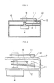
- FIGs.1 and 2 illustrate a variable resistor usable in the invention.
- arm member (2) having magnet (1) at its end is fixed about shaft (3) of rotary variable resistor (4) comprising a resistive element and a sliding member that moves in contact with the resistive element when shaft (3) rotates.
- Arm member (2) and rotary variable resistor (4) are enclosed in moistureproof container (6) having cylindrical projection (5).
- Stopper (9) is used to rotatably attach L-shaped guide member (11) having magnet (10) to flat surface (8) of projection (5) so that one pole of magnet (10) can face to opposite pole of magnet (6) across cylindrical wall (12) of projection (5).
- Knob (13) is attached to stopper (9), while dial (14) is provided on flat surface (8) of projection (5).
- dial (13) By dialing knob (14) according to dial (14) to move guide member (11), arm member (2) and shaft (3) are rotated magnetically in association with the movement of guide member (11).
- a desired level of electric resistance can be attained with variable resistance (4).
- a desired level of low-frequency voltage can be obtained from a low-frequency oscillator by inserting the variable resistor between the output terminal of the low-frequency oscillator and an elec trode, and dialing knob (1) according to dial (14).
- FIG.3 shows another embodiment according to the invention, wherein moistureproof container (6) is shaped into a cylinder by providing in the embodiment in FIG.1 hearing (15), such as ball or roller bearing, between arm member (2) and the inside wall of moistureproof container (6).
- 15 such as ball or roller bearing
- This embodiment is characterized in that it can be produced in a smaller size and at a lower cost in comparison with the previous embodiment.
- Variable resistor (4) enclosed in moistureproof container (6) may be a slide a variable resistor, and should not be restricted to rotary variable resistor as shown in FIGs.1 and 3.
- a slide variable resistor a linear resistive element and a sliding member with magnet are enclosed in moistureproof container (6) in such manner that the sliding member moves in contact with the resistive element, while a guide member having magnet is movably attached outside container (6) at an appropriate distance from the sliding member along with the resistive element.
- magnet (1) or 10 in FIGs.1 and 3 may be a magnetic piece such as that of iron or nickel, an increased attraction and a stable operation can be attained by making them with magnet.
- the arm member and/or guide member consists partially or entirely of magnet or a magnetic piece.
- FIGs.4 and 5 illustrate a switch structure that can be advantageously used in the device according to the invention.
- spring arm member (2) and contact (16) are attached around shaft (3) of rotary variable resistor (4) in such manner that they move together and attract each other into conduction when one pole of magnet (1) faces to opposite pole of magnet (10) across side wall (17) of moistureproof container (6).
- FIG.5 is illustrative of a power switch wherein arm member (2) contacts with contact (18) to separate contacts (18) and (19) when it is at the minimum resistance position.
- FIG.6 is the circuit of a low-frequency oscillator usable in the invention.
- the multivibrator comprising transistors T1 and T2 oscillates a positive square wave, for example, having a pulse interval of 0.1-10 seconds and a pulse width of 0.1-10 seconds, which is then modified by transistor T3 and resistor R5 into a saturated wave voltage as shown in FIG.7.
- the blocking oscillator including transistor T4 is to generate a diphasic action potential, and the transistor becomes conductive whenever the saturated wave voltage supplied to the base comes to the positive region.
- the blocking oscillator generates a diphasic action potential at time intervals equal to the pulse width of the square wave.
- dispersive electrode E When dispersive electrode E is placed, for example, on a non-affected site of the skin or in bath water and active electrode P comes nearly to or on load Z such as subject's body, the area between dispersive and active electrodes E and P become conductive through load Z. When this occurs, the current from dispersive electrode E charges capacitor C10 through active electrode P, resistor R10, diode D, and resistor R11 and the voltage across capacitor C7 conducts transistor T5, transistors T1 and T2 receive the emitter current and the multivibrator begins oscillation.
- the output square wave voltage is modified by transistor T6 into a saturated wave voltage, and supplied to the base of transistor T4 through resistor R5 and the emitter follower circuit including transistor T3.
- Transistor T4 generates diphasic action potential when the voltage supplied to the base is not zero, and the output is controlled with variable resistor VR and then supplied between active and dispersive electrodes P and E.
- Discharge of battery B never continue if the subject forgets to open power switch S because conduction of transistor T5 is interrupted and operation of multivibrator and blocking oscillator is stopped when no current flows across dispersive and active electrodes E and P.
- variable resistor Since the device according to the invention the variable resistor is not exposed to moisture even when used in a humid environment such as bath, the moisture never disturbs the operation of the device.
- variable resistor can be immersed in bath water, the subject can control while in bath the dosage of low- frequency voltage.
- the device can be advantageously used in the improvement and treatment of blood circulation, muscular strength, muscular fatigue, massage, and haemorrhoids.
- the device equipped with an oscillator circuit exerts a remarkable therapeutic effect when used while taking a bath: At a frequency of 100 hertz or lower, preferably, 10-70 hertz, the device is effective in improvement and treatment of blood circulation, muscular strength, fatigue and haemorrhoids; and at a frequency of 100-300 hertz, in prevention of alopecia as well as in acceleration and regeneration of hair.
Landscapes
- Health & Medical Sciences (AREA)
- Engineering & Computer Science (AREA)
- Life Sciences & Earth Sciences (AREA)
- General Health & Medical Sciences (AREA)
- Biomedical Technology (AREA)
- Nuclear Medicine, Radiotherapy & Molecular Imaging (AREA)
- Radiology & Medical Imaging (AREA)
- Animal Behavior & Ethology (AREA)
- Public Health (AREA)
- Veterinary Medicine (AREA)
- Microelectronics & Electronic Packaging (AREA)
- Heart & Thoracic Surgery (AREA)
- Biophysics (AREA)
- Electrotherapy Devices (AREA)
- Devices For Medical Bathing And Washing (AREA)
Applications Claiming Priority (2)
| Application Number | Priority Date | Filing Date | Title |
|---|---|---|---|
| JP133326/86U | 1986-08-31 | ||
| JP1986133326U JPH033338Y2 (fr) | 1986-08-31 | 1986-08-31 |
Publications (3)
| Publication Number | Publication Date |
|---|---|
| EP0262800A2 true EP0262800A2 (fr) | 1988-04-06 |
| EP0262800A3 EP0262800A3 (en) | 1990-07-18 |
| EP0262800B1 EP0262800B1 (fr) | 1994-04-13 |
Family
ID=15102093
Family Applications (1)
| Application Number | Title | Priority Date | Filing Date |
|---|---|---|---|
| EP87307662A Expired - Lifetime EP0262800B1 (fr) | 1986-08-31 | 1987-08-28 | Dispositif pour l'électrothérapie à basse fréquence |
Country Status (7)
| Country | Link |
|---|---|
| US (1) | US4960125A (fr) |
| EP (1) | EP0262800B1 (fr) |
| JP (1) | JPH033338Y2 (fr) |
| KR (1) | KR950011792B1 (fr) |
| BR (1) | BR8704423A (fr) |
| CA (1) | CA1295704C (fr) |
| DE (1) | DE3789588T2 (fr) |
Cited By (1)
| Publication number | Priority date | Publication date | Assignee | Title |
|---|---|---|---|---|
| EP0430612A3 (en) * | 1989-11-28 | 1992-06-03 | Hayashibara, Ken | Sealed variable resistor |
Families Citing this family (2)
| Publication number | Priority date | Publication date | Assignee | Title |
|---|---|---|---|---|
| US9421367B1 (en) | 2000-08-24 | 2016-08-23 | Electroregenesis, Inc. | Method and apparatus for performing microcurrent electrotherapy |
| DE202004016208U1 (de) * | 2004-10-20 | 2005-05-04 | Malzahn, Heinz Herbert | Computermaus mit 1-Fingersteuerung |
Family Cites Families (18)
| Publication number | Priority date | Publication date | Assignee | Title |
|---|---|---|---|---|
| DE581370C (de) * | 1928-02-03 | 1933-07-26 | Siemens & Halske Akt Ges | Magnetische Kupplung, insbesondere fuer Messzwecke |
| AT148644B (de) * | 1933-07-14 | 1937-02-10 | Siemens Ag | Regelbarer elektrischer Widerstand. |
| AT141438B (de) * | 1934-03-06 | 1935-04-25 | Ludwig Ing Salamon | Mit einem Schalter zusammengebauter, einstellbarrer Widerstand. |
| US2467497A (en) * | 1946-05-17 | 1949-04-19 | Electra Voice Corp | Rheostat with magnetic operator |
| US3518604A (en) * | 1968-02-12 | 1970-06-30 | Cts Corp | Electrical component |
| DE1908398B2 (de) * | 1969-02-20 | 1971-11-25 | Weller, Eugen, Dr.med., 7310Plochingen | Galvanisches heilgeraet zur durchstroemung des menschlichen koerpers |
| DE2262385A1 (de) * | 1972-12-20 | 1974-06-27 | Neuro Systems Inc | Elektrotherapiegeraet |
| FR2245386A1 (en) * | 1973-08-10 | 1975-04-25 | Gouttebessis Rene | Electro-therapeutic electronic pulse generator unit - has static interrupter followed by generator and final amplifier |
| JPS5162582A (ja) * | 1974-11-26 | 1976-05-31 | Kazumi Masaki | Yokusoyoteishuhachiryoki |
| US3986144A (en) * | 1975-06-16 | 1976-10-12 | Joseph Russo | Oscillator with blinking light emitting diode for ornamental ring |
| JPS52141093A (en) * | 1976-05-19 | 1977-11-25 | Nippon Koinko Kk | Low frequency curing device |
| DE2712101A1 (de) * | 1977-03-19 | 1978-10-05 | Petrus G Saraber | Verfahren zur erzeugung von wechselstroemen und geraet fuer deren anwendung zu medizinischen zwecken |
| DE2758856C2 (de) * | 1977-12-30 | 1986-09-25 | Conducta Gesellschaft für Meß- und Regeltechnik mbH & Co, 7016 Gerlingen | Meßwertumformer, insbesondere für direkt messende Betriebsanalysengeräte |
| DE2919671C2 (de) * | 1979-05-16 | 1983-07-14 | G. Kromschröder AG, 4500 Osnabrück | Magnetische Durchführung für Durchflußzähler |
| US4249537A (en) * | 1979-05-18 | 1981-02-10 | Chaconas Charles G | Current controlled muscle stimulator |
| JPS5810109B2 (ja) * | 1979-06-15 | 1983-02-24 | 松下電工株式会社 | 低周波治療器 |
| DE3346673A1 (de) * | 1983-12-23 | 1984-05-03 | Wolfgang 8201 Neubeuern Preywisch | Reizstromtherapiegeraet fuer die medizinisch therapeutische und/oder diagnostische anwendung |
| JPH05162582A (ja) * | 1991-12-16 | 1993-06-29 | Honda Motor Co Ltd | 車両用灯体の点灯制御装置 |
-
1986
- 1986-08-31 JP JP1986133326U patent/JPH033338Y2/ja not_active Expired
-
1987
- 1987-08-27 BR BR8704423A patent/BR8704423A/pt not_active IP Right Cessation
- 1987-08-28 DE DE3789588T patent/DE3789588T2/de not_active Expired - Fee Related
- 1987-08-28 EP EP87307662A patent/EP0262800B1/fr not_active Expired - Lifetime
- 1987-08-28 CA CA000545650A patent/CA1295704C/fr not_active Expired - Lifetime
- 1987-08-31 KR KR1019870009538A patent/KR950011792B1/ko not_active Expired - Fee Related
-
1988
- 1988-10-26 US US07/265,291 patent/US4960125A/en not_active Expired - Fee Related
Cited By (1)
| Publication number | Priority date | Publication date | Assignee | Title |
|---|---|---|---|---|
| EP0430612A3 (en) * | 1989-11-28 | 1992-06-03 | Hayashibara, Ken | Sealed variable resistor |
Also Published As
| Publication number | Publication date |
|---|---|
| KR950011792B1 (ko) | 1995-10-10 |
| DE3789588T2 (de) | 1994-08-25 |
| CA1295704C (fr) | 1992-02-11 |
| JPS6340953U (fr) | 1988-03-17 |
| EP0262800B1 (fr) | 1994-04-13 |
| DE3789588D1 (de) | 1994-05-19 |
| JPH033338Y2 (fr) | 1991-01-29 |
| BR8704423A (pt) | 1988-04-19 |
| US4960125A (en) | 1990-10-02 |
| KR880002547A (ko) | 1988-05-09 |
| EP0262800A3 (en) | 1990-07-18 |
Similar Documents
| Publication | Publication Date | Title |
|---|---|---|
| US5030196A (en) | Magnetic treatment device | |
| KR960012203B1 (ko) | 저주파 치료기 | |
| US7566839B2 (en) | Contact-breaker device, circuit and apparatus comprising the same, and method for assembling contact-breaker device | |
| US6223076B1 (en) | Sweat control system | |
| JP2004535235A (ja) | D字型刺激電極を備えた電気鍼装置 | |
| DE69133328D1 (de) | Vorrichtung zur iontophoretischen verabreichung | |
| RU2355437C2 (ru) | Устройство для электротерапии | |
| JPS62139672A (ja) | 正負イオントホレ−ゼ用治療器 | |
| JP2004121528A (ja) | マッサージ器 | |
| US5385150A (en) | Acupuncture device | |
| US6026327A (en) | Hand held electrical stimulator for pain relief using cylindrical electrode head | |
| US4960125A (en) | Device for low-frequency electrotherapy in a humid environment | |
| FR2307554A1 (fr) | Appareil de vibro-massage electronique et de desincrustation dont l'electrode passive est constituee par le corps de l'appareil, et fonctionnant sur une alimentation autonome rechargeable | |
| FI96385C (fi) | Laite imunesteiden salpautumien ja vastaavien hoitamiseksi | |
| US4792777A (en) | Variable water resistor for controlling the application of a therapeutic voltage to the human body | |
| US5144274A (en) | Sealed variable resistor | |
| JPH0433862Y2 (fr) | ||
| RU1783983C (ru) | Устройство дл электрорефлексотерапии | |
| ES2134150A1 (es) | "peine para el cuidado de la salud". | |
| JP4854883B2 (ja) | 貼付用磁気治療器 | |
| KR910005289Y1 (ko) | 무색의 금속박을 이용한 파스 | |
| US3015333A (en) | Device for electrical contraction of bodily tissues | |
| JPH0640902B2 (ja) | 低周波治療器 | |
| JPS626823B2 (fr) | ||
| RU2001118822A (ru) | Способ нейромышечной электростимуляции и электростимулятор |
Legal Events
| Date | Code | Title | Description |
|---|---|---|---|
| PUAI | Public reference made under article 153(3) epc to a published international application that has entered the european phase |
Free format text: ORIGINAL CODE: 0009012 |
|
| AK | Designated contracting states |
Kind code of ref document: A2 Designated state(s): DE FR GB |
|
| PUAL | Search report despatched |
Free format text: ORIGINAL CODE: 0009013 |
|
| AK | Designated contracting states |
Kind code of ref document: A3 Designated state(s): DE FR GB |
|
| 17P | Request for examination filed |
Effective date: 19901222 |
|
| 17Q | First examination report despatched |
Effective date: 19911223 |
|
| GRAA | (expected) grant |
Free format text: ORIGINAL CODE: 0009210 |
|
| AK | Designated contracting states |
Kind code of ref document: B1 Designated state(s): DE FR GB |
|
| REF | Corresponds to: |
Ref document number: 3789588 Country of ref document: DE Date of ref document: 19940519 |
|
| ET | Fr: translation filed | ||
| PLBE | No opposition filed within time limit |
Free format text: ORIGINAL CODE: 0009261 |
|
| STAA | Information on the status of an ep patent application or granted ep patent |
Free format text: STATUS: NO OPPOSITION FILED WITHIN TIME LIMIT |
|
| 26N | No opposition filed | ||
| PGFP | Annual fee paid to national office [announced via postgrant information from national office to epo] |
Ref country code: FR Payment date: 19970813 Year of fee payment: 11 |
|
| PGFP | Annual fee paid to national office [announced via postgrant information from national office to epo] |
Ref country code: GB Payment date: 19970819 Year of fee payment: 11 |
|
| PGFP | Annual fee paid to national office [announced via postgrant information from national office to epo] |
Ref country code: DE Payment date: 19970924 Year of fee payment: 11 |
|
| PG25 | Lapsed in a contracting state [announced via postgrant information from national office to epo] |
Ref country code: GB Free format text: LAPSE BECAUSE OF NON-PAYMENT OF DUE FEES Effective date: 19980828 |
|
| GBPC | Gb: european patent ceased through non-payment of renewal fee |
Effective date: 19980828 |
|
| PG25 | Lapsed in a contracting state [announced via postgrant information from national office to epo] |
Ref country code: FR Free format text: LAPSE BECAUSE OF NON-PAYMENT OF DUE FEES Effective date: 19990430 |
|
| PG25 | Lapsed in a contracting state [announced via postgrant information from national office to epo] |
Ref country code: DE Free format text: LAPSE BECAUSE OF NON-PAYMENT OF DUE FEES Effective date: 19990601 |
|
| REG | Reference to a national code |
Ref country code: FR Ref legal event code: ST |