EP0262878B1 - Connecteur pour des fibres optiques - Google Patents
Connecteur pour des fibres optiques Download PDFInfo
- Publication number
- EP0262878B1 EP0262878B1 EP87308513A EP87308513A EP0262878B1 EP 0262878 B1 EP0262878 B1 EP 0262878B1 EP 87308513 A EP87308513 A EP 87308513A EP 87308513 A EP87308513 A EP 87308513A EP 0262878 B1 EP0262878 B1 EP 0262878B1
- Authority
- EP
- European Patent Office
- Prior art keywords
- holes
- segments
- connector
- optical
- further characterized
- Prior art date
- Legal status (The legal status is an assumption and is not a legal conclusion. Google has not performed a legal analysis and makes no representation as to the accuracy of the status listed.)
- Expired - Lifetime
Links
- 239000013307 optical fiber Substances 0.000 title description 25
- 230000003287 optical effect Effects 0.000 claims description 25
- 239000000463 material Substances 0.000 claims description 11
- 239000012780 transparent material Substances 0.000 claims description 4
- 239000004020 conductor Substances 0.000 claims 7
- 230000008878 coupling Effects 0.000 claims 2
- 238000010168 coupling process Methods 0.000 claims 2
- 238000005859 coupling reaction Methods 0.000 claims 2
- 239000007787 solid Substances 0.000 claims 1
- 239000000835 fiber Substances 0.000 description 35
- 238000009413 insulation Methods 0.000 description 3
- 230000001681 protective effect Effects 0.000 description 3
- 239000011248 coating agent Substances 0.000 description 2
- 238000000576 coating method Methods 0.000 description 2
- 238000004519 manufacturing process Methods 0.000 description 2
- 229920003229 poly(methyl methacrylate) Polymers 0.000 description 2
- 239000004926 polymethyl methacrylate Substances 0.000 description 2
- BQCADISMDOOEFD-UHFFFAOYSA-N Silver Chemical compound [Ag] BQCADISMDOOEFD-UHFFFAOYSA-N 0.000 description 1
- XAGFODPZIPBFFR-UHFFFAOYSA-N aluminium Chemical compound [Al] XAGFODPZIPBFFR-UHFFFAOYSA-N 0.000 description 1
- 229910052782 aluminium Inorganic materials 0.000 description 1
- 239000012530 fluid Substances 0.000 description 1
- -1 for example Substances 0.000 description 1
- PCHJSUWPFVWCPO-UHFFFAOYSA-N gold Chemical compound [Au] PCHJSUWPFVWCPO-UHFFFAOYSA-N 0.000 description 1
- 229910052737 gold Inorganic materials 0.000 description 1
- 239000010931 gold Substances 0.000 description 1
- 238000000034 method Methods 0.000 description 1
- 238000005498 polishing Methods 0.000 description 1
- 229920001296 polysiloxane Polymers 0.000 description 1
- 229910052709 silver Inorganic materials 0.000 description 1
- 239000004332 silver Substances 0.000 description 1
Images


Classifications
-
- G—PHYSICS
- G02—OPTICS
- G02B—OPTICAL ELEMENTS, SYSTEMS OR APPARATUS
- G02B6/00—Light guides; Structural details of arrangements comprising light guides and other optical elements, e.g. couplings
- G02B6/24—Coupling light guides
- G02B6/26—Optical coupling means
-
- G—PHYSICS
- G02—OPTICS
- G02B—OPTICAL ELEMENTS, SYSTEMS OR APPARATUS
- G02B6/00—Light guides; Structural details of arrangements comprising light guides and other optical elements, e.g. couplings
- G02B6/24—Coupling light guides
- G02B6/26—Optical coupling means
- G02B6/28—Optical coupling means having data bus means, i.e. plural waveguides interconnected and providing an inherently bidirectional system by mixing and splitting signals
- G02B6/2804—Optical coupling means having data bus means, i.e. plural waveguides interconnected and providing an inherently bidirectional system by mixing and splitting signals forming multipart couplers without wavelength selective elements, e.g. "T" couplers, star couplers
- G02B6/2817—Optical coupling means having data bus means, i.e. plural waveguides interconnected and providing an inherently bidirectional system by mixing and splitting signals forming multipart couplers without wavelength selective elements, e.g. "T" couplers, star couplers using reflective elements to split or combine optical signals
-
- G—PHYSICS
- G02—OPTICS
- G02B—OPTICAL ELEMENTS, SYSTEMS OR APPARATUS
- G02B6/00—Light guides; Structural details of arrangements comprising light guides and other optical elements, e.g. couplings
- G02B6/24—Coupling light guides
- G02B6/26—Optical coupling means
- G02B6/262—Optical details of coupling light into, or out of, or between fibre ends, e.g. special fibre end shapes or associated optical elements
Definitions
- the invention relates to an optical fiber connector.
- Known optical fiber connectors typically comprise a plurality of individual parts, at least two of which must be machined to very close tolerances. These arrangements are, therefore, relatively expensive to manufacture. Moreover, the complexity and cost of such connectors increase substantially when they are adapted to connect more than two optical fibers together.
- a spherical mirror is formed at one end of a body of transparent material. Holes formed in the body of the material receive optical fibers such that an optical signal emitted by a fiber in one of the holes impinges on the spherical mirror where it is reflected to a fiber inserted in the other hole, thereby establishing a connection between the fibers.
- N segments of respective spherical mirrors are formed at one end of the connector allowing at least N+1 fibers to be connected together, the N+1 fibers being inserted in respective holes formed in the connector.
- the segments may be of unequal size, thereby providing a way of distributing different amounts of light to different receiving fibers.
- connector 10 is formed from a body of transparent material, for example, polymethyl methacrylate, such that a spherical surface 12 is formed at one end 16 of connector 10.
- the interior of spherical surface 12 serves as a mirror having a radius of curvature of illustratively 5 millimeters.
- the exterior of spherical surface 12 is coated with a reflective material 13, for example, aluminum, silver or gold, to reflect optical signals impinging thereon, the optical signals being emitted by optical fibers (not shown) inserted in holes 14 and 15, respectively.
- a reflective material 13 for example, aluminum, silver or gold
- Cylindrical shaped optical fiber receiving holes 14 and 15 are formed in the body 11 of connector 10 such that the bottoms of the holes are in line with the center of curvature C of spherical mirror 12.
- the centers of holes 14 and 15 are disposed equally distant from the principal axis m of the spherical mirror 12 and are placed on opposite sides of the axis.
- holes 14 and 15 are each 1 centimeter deep and the centers thereof are each disposed 250 microns from axis m. The depth of holes 14 and 15 and thus the length of connector 10 from C to end 16 does not affect the operation of connector 10 as long as the bottoms of the holes are in line with the center of curvature C of spherical mirror 12.
- holes 14 and 15 may be formed to accommodate a particular gauge of optical fiber. Accordingly, it is an aspect of the invention to provide a plurality of connectors 10, each being adapted to receive a particular gauge of optical fiber. It is also an aspect of the invention to arrange connector 10 to accept two different gauges of optical fiber, e.g., a connector in which the diameter of hole 14 is adapted to accept one particular gauge of optical fiber and in which the diameter of hole 15 is adapted to accept another gauge of optical fiber.
- the end 16 of connector 10 in accordance with the invention, is split along the center thereof, forming a gap 9. Also, an upper portion 19 of the body 11 of connector 10 is tapered and threaded, as shown. When threaded nut 18 is threaded onto tapered threads 17, the gap 9 closes, thereby causing connector 10 to grip the fibers and hold them securely in place. It is to be understood by the art that optical fibers could be, for example, cemented in place once they have been inserted in boles 14 and 15.
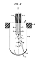
- FIG. 2 there is shown a cross-section of connector 10 with optical fibers 19 and 20 inserted into holes 14 and 15, respectively.
- the ends of optical fibers 19 and 20 are prepared in the conventional manner prior to inserting them into holes 14 and 15, respectively, i.e., the end of protective insulation 21 and 22 is removed from the fibers and the fibers are cut to the length (depth) of holes 14 and 15 using the well known score-and-break technique.
- the protective insulation may be left in place provided that the diameters of the holes in the connector are sufficiently large to accommodate the fibers and their protective insulation.
- the end surfaces of the fibers may be polished if desired.
- optical interface between the fibers 19 and 20 and the bottoms of holes 14 and 15, respectively may be improved by, for example, polishing the bottoms of holes 14 and 15 or by adding an index matching fluid, for example, a silicone gel, to holes 14 and 15.)
- an index matching fluid for example, a silicone gel
- Connector 10 establishes, in accordance with the invention, an optical connection between the fibers 19 and 20 once the fibers 19 and 20 have been inserted in holes 14 and 15, respectively, as shown.
- an optical signal emitted by a small source, such as fiber 20 spreads out in the form of a conical beam.
- ray p of the beam is shown in FIG. 2.
- ray p impinges on mirror 12 at a particular angle of incidence and is reflected at a particular angle of reflection, the reflected ray being designated q.
- the angle of incidence may be determined by extending a line r from the center of curvature C of mirror 12 to the point n at which ray p strikes mirror 12, the length of line r being the radius of curvature of mirror 12 and being perpendicular to mirror 12 at point n.
- the angle of incidence is then the angle ⁇ between the path of ray p and the radius of curvature r. Since, according to Snells' law, the angle of incidence equals the angle of reflection, ray q is reflected at an angle ⁇ . It is well known that since the angle of reflection of ray q equals the angle of incidence of ray p, ray q is reflected in a direction that is the same as but is opposite to the direction of ray p. Accordingly, ray q impinges on fiber 19, thereby establishing, in accordance with the invention, an optical connection between fibers 19 and 20.
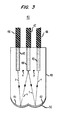
- FIG. 3 there is shown a cross-section of a second embodiment of the invention that is arranged to connect three optical fibers 46, 47 and 48 together.
- the optical fibers may be cemented in place once they have been inserted into respective ones of holes 43 through 45, which is the case in FIG. 3 and the following FIG. 4 discussed below.
- connector 40 is illustratively molded from a transparent material, for example, the aforementioned polymethyl methacrylate, such that two spherical segments 41 and 42 are formed at one end of connector 40, as shown.
- the center of curvature of spherical segment 41 and the center of curvature of spherical segment 42 are represented by points x and y, respectively.
- the exteriors of spherical segments 41 and 42 are coated with the aforementioned reflective material (designated 50 in FIG. 3) so that they may operate as spherical mirrors.
- Holes 43, 44 and 45 are formed in the body 49 of connector 40 to a depth which is in line with points x and y.
- the center of hole 44 is positioned at the midpoint between points x and y and hole 43 (45) is the same distance from point x (y) as is hole 44.
- optical signals such as light rays, emitted by fiber 47 from hole 44 impinge on both segments 41 and 42, as represented by rays s and t, respectively.
- the light rays s and t impinging on segments 41 and 42, respectively, are reflected by the reflective material 50 (the reflected rays being designated u and v, respectively) in the direction of holes 43 and 45 where the rays u and v are received by the fibers 46 and 48, respectively.
- fibers 46 and 48 are substantially decoupled from each other.
- one of the segments could be smaller than the other segment.
- the level, or strength, of the optical signal received by fiber 46 from fiber 47 would be less than the strength of the signal received by fiber 48.
- the invention of FIG. 3 may be arranged such that only a small portion of the optical signal is directed to fiber 46, which signal could then be used to monitor the strength of the signal emitted by fiber 47.
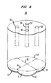
- FIG. 4 there is shown a third embodiment of the invention adapted to connect illustratively five optical fibers together.
- four spherical segments 51 through 54 are formed at one end of connector 50 and the outer surfaces thereof are coated with the previously mentioned reflective material (designated 60 in FIG. 5).
- dashed lines 61 and 62 which would not be seen in an actual embodiment of connector 50, highlight the fact that connector 50 comprises four segments.
- Five holes 55 through 59 are formed in the body of connector 50 for receiving respective optical fibers (not shown). Hole 55 is disposed at the center of the connector and the center of curvature of each of segments 51 through 54 is equally distant from the center of hole 55 and the center of a respective ones of holes 56 through 59.
- Connector 50 operates similar to the way connector 40 of FIG. 3 operates. Specifically, optical signals emitted by a fiber inserted in the central hole-hole 55--impinge on segments 51 through 54.
- the reflective coating 60 on the outer surfaces of the segments reflects the signals impinging thereon in the direction of holes 56 through 59, respectively.
- signals emitted by a fiber inserted in one of the holes 56 through 59 impinge on its respective one of spherical segments 51 through 54 where the reflective coating 60 reflects the signals in the direction of central hole 55.
- FIGS. 5, 6 and 7 illustrate top views of connectors 10, 40 and 50, respectively. It is to be understood that the top portions of connectors 40 and 50 are, according to the present invention (although not shown in the drawings), circular and split to a predetermined depth and have tapered threads for receiving a threaded nut, or collar, as is shown for connector 10 in FIGS. 1 and 2.
Landscapes
- Physics & Mathematics (AREA)
- General Physics & Mathematics (AREA)
- Optics & Photonics (AREA)
- Optical Couplings Of Light Guides (AREA)
- Mechanical Coupling Of Light Guides (AREA)
Claims (7)
- Un connecteur optique (10) pour coupler un conducteur de signal optique avec au moins un autre conducteur de signal optique, ce connecteur étant formé à partir d'un bloc plein en une matière transparente (11) ayant des première (16) et seconde (13) extrémités opposées, ce bloc comprenant :
un ensemble de trous (14, 15) ayant des profondeurs prédéterminées respectives, qui sont formés dans la première extrémité (16), et
au moins une surface sphérique (13) revêtue avec un matériau réfléchissant (12), formée à la seconde extrémité (13), la forme de la surface sphérique ou des surfaces sphériques (13) et les profondeurs prédéterminées des extrémités intérieures des trous (14, 15), ainsi que leurs écartements par rapport à l'axe principal (m) de la surface sphérique (13), étant tels que des signaux lumineux (p) qui sont émis par un conducteur de signal optique (par exemple 22) introduit dans l'un des trous (par exemple 15), tombent sur la surface sphérique (13) et sont réfléchis par la surface réfléchissante (12) vers au moins un autre conducteur de signal optique (par exemple 21) qui est introduit dans un autre des trous (par exemple 14),
CARACTERISE EN CE QUE
la première extrémité (16) est fendue selon une ligne qui traverse les trous (14, 15), jusqu'à une profondeur prédéterminée, pour former un espace (9), et l'extérieur du bloc de matière (11), à la première extrémité (16), a une forme tronconique et est fileté (17), de façon que lorsqu'un écrou (18) ayant un filetage intérieur est vissé sur le filetage extérieur tronconique (17) du bloc, l'espace (9) se ferme, ce qui fait que l'extrémité fendue serre les conducteurs de signal (21, 22) qui sont introduits dans des trous respectifs (14, 15) de l'ensemble de trous. - Le connecteur optique de la revendication 1
CARACTERISE EN OUTRE EN CE QUE
la surface sphérique ou les surfaces sphériques (13) revêtues avec la matière réfléchissante, forment au moins un miroir sphérique (12, 13) à la seconde extrémité du bloc de matière (11). - Le connecteur optique de la revendication 1
CARACTERISE EN OUTRE EN CE QUE
les extrémités intérieures des trous (14, 15) rencontrent une ligne qui passe par le centre de courbure (c) de la surface sphérique ou des surfaces sphériques (13). - Le connecteur optique de la revendication 1, destiné à coupler un conducteur de signal optique avec un ensemble d'autres conducteurs de signal optique,
CARACTERISE EN OUTRE EN CE QUE
un ensemble de segments de surfaces courbes respectives (par exemple 41, 42 ou 51, 52, 53, 54), sont formés dans la seconde extrémité (13), l'extérieur de chacun de ces segments étant revêtu avec une matière réfléchissante (par exemple 50 ou 60), pour former des segments respectifs de miroirs sphériques. - Le connecteur optique de la revendication 4
CARACTERISE EN OUTRE EN CE QUE
l'un au moins des segments de l'ensemble de segments de surfaces courbes (par exemple 52) est plus petit qu'au moins un autre segment (par exemple 53) de l'ensemble de segments de surfaces courbes. - Le connecteur optique de la revendication 4
CARACTERISE EN OUTRE EN CE QUE
chaque trou (par exemple 55, 56, 57, 58, 59) comporte une extrémité intérieure qui est disposée à la même distance de l'axe principal de son segment respectif, parmi l'ensemble de segments de surfaces courbes (par exemple 51, 52, 53, 54). - Le connecteur optique de la revendication 4
CARACTERISE EN OUTRE EN CE QUE
l'un au moins des trous de l'ensemble de trous (par exemple 44) est disposé à une distance égale de l'axe principal (par exemple x, y) de chaque segment de l'ensemble de segments de surfaces courbes (par exemple 41, 42).
Applications Claiming Priority (2)
| Application Number | Priority Date | Filing Date | Title |
|---|---|---|---|
| US06/915,263 US4763978A (en) | 1986-10-03 | 1986-10-03 | Optical fiber connector |
| US915263 | 1986-10-03 |
Publications (3)
| Publication Number | Publication Date |
|---|---|
| EP0262878A2 EP0262878A2 (fr) | 1988-04-06 |
| EP0262878A3 EP0262878A3 (en) | 1989-08-09 |
| EP0262878B1 true EP0262878B1 (fr) | 1993-06-16 |
Family
ID=25435473
Family Applications (1)
| Application Number | Title | Priority Date | Filing Date |
|---|---|---|---|
| EP87308513A Expired - Lifetime EP0262878B1 (fr) | 1986-10-03 | 1987-09-25 | Connecteur pour des fibres optiques |
Country Status (6)
| Country | Link |
|---|---|
| US (1) | US4763978A (fr) |
| EP (1) | EP0262878B1 (fr) |
| JP (1) | JP2679787B2 (fr) |
| KR (1) | KR910001502B1 (fr) |
| CA (1) | CA1302757C (fr) |
| DE (1) | DE3786217T2 (fr) |
Families Citing this family (16)
| Publication number | Priority date | Publication date | Assignee | Title |
|---|---|---|---|---|
| US4993796A (en) * | 1979-08-14 | 1991-02-19 | Kaptron, Inc. | Fiber optics communication modules |
| US4902093A (en) * | 1988-07-22 | 1990-02-20 | Amp Incorporated | Laser diode to fiber reflective coupling |
| US4968113A (en) * | 1989-04-05 | 1990-11-06 | Amp Incorporated | Optical fiber nut |
| US5134674A (en) * | 1989-12-05 | 1992-07-28 | Amp Incorporated | Reflection coupling of optical fibers |
| WO1991009330A1 (fr) * | 1989-12-18 | 1991-06-27 | E.I. Du Pont De Nemours And Company | Contact fibroptique a reflecteur cintre |
| GB9116942D0 (en) * | 1991-08-06 | 1991-10-09 | Marconi Gec Ltd | Optical fibre arrangement |
| US5857041A (en) * | 1995-01-17 | 1999-01-05 | Remote Source Lighting International | Optical coupler and method utilizing optimal illumination reflector |
| JPH08271337A (ja) * | 1995-03-31 | 1996-10-18 | Yokogawa Electric Corp | 分光器 |
| US5727101A (en) * | 1995-10-06 | 1998-03-10 | Siecor Corporation | Monolithic ferrule for receiving and positioning multiple optical fibers and an optical fiber connector incorporating same |
| GB9706729D0 (en) * | 1997-04-03 | 1997-05-21 | Cable & Wireless Ltd | Method and apparatus for joining underwater cable |
| JP3699852B2 (ja) * | 1999-02-17 | 2005-09-28 | シャープ株式会社 | 双方向光通信器および双方向光通信装置 |
| EP1347317A4 (fr) * | 2000-12-28 | 2006-11-08 | Univ Keio | Circuit de traitement de signaux optiques et procede de fabrication |
| EP1225465B1 (fr) * | 2001-01-19 | 2003-10-15 | Optosys SA | Dispositif optique |
| US6896418B1 (en) * | 2002-06-21 | 2005-05-24 | Realm Communications Group, Inc. | Planar polishing fixture |
| US7239385B2 (en) | 2004-11-30 | 2007-07-03 | Hutchinson Technology Incorporated | Method and apparatus for monitoring output signal instability in a light source |
| JP2014102304A (ja) * | 2012-11-19 | 2014-06-05 | Fuji Electric Co Ltd | 光合波装置 |
Family Cites Families (29)
| Publication number | Priority date | Publication date | Assignee | Title |
|---|---|---|---|---|
| US3883223A (en) * | 1974-04-08 | 1975-05-13 | Corning Glass Works | Coupler for optical communication system |
| US4155624A (en) * | 1976-12-23 | 1979-05-22 | Thomas & Betts Corporation | Duplex optical fiber connector |
| US4145110A (en) * | 1977-04-08 | 1979-03-20 | Northern Telecom Limited | Optical fibre connector for variable signal attenuation |
| US4365864A (en) * | 1979-08-10 | 1982-12-28 | National Research Development Corporation | Optical fibre multiport couplers |
| US4329017A (en) * | 1979-08-14 | 1982-05-11 | Kaptron, Inc. | Fiber optics communications modules |
| DE3002473A1 (de) * | 1980-01-24 | 1981-09-17 | Teldix Gmbh, 6900 Heidelberg | Loesbare kupplung zum verbinden von insbesondere mehreren lichtwellenleitern |
| US4291941A (en) * | 1980-02-04 | 1981-09-29 | The Deutsch Company Electronic Components Division | Optical fiber connector |
| JPS56145014U (fr) * | 1980-03-31 | 1981-11-02 | ||
| CA1158465A (fr) * | 1980-07-08 | 1983-12-13 | Mitsuaki Nishie | Connecteur optique |
| FR2492543A2 (fr) * | 1980-10-21 | 1982-04-23 | Thomson Csf | Epissures entre fibres optiques |
| JPS5785017A (en) * | 1980-11-17 | 1982-05-27 | Fujitsu Ltd | Optical distributor |
| JPS57199304U (fr) * | 1981-01-28 | 1982-12-17 | ||
| DE3175395D1 (en) * | 1981-02-20 | 1986-11-06 | Kaptron Inc | Fiber optics communications modules |
| CA1154987A (fr) * | 1981-11-27 | 1983-10-11 | Narinder S. Kapany | Module de telecommunication par fibres optiques |
| FR2507330A1 (fr) * | 1981-06-05 | 1982-12-10 | Instruments Sa | Dispositif de commutation entre fibres optiques |
| JPS5813511U (ja) * | 1981-07-20 | 1983-01-27 | 三洋電機株式会社 | 光ビ−ム分割,統合具 |
| JPS5834421A (ja) * | 1981-08-25 | 1983-02-28 | Moritetsukusu:Kk | 光通信素子 |
| US4465333A (en) * | 1982-01-15 | 1984-08-14 | Grumman Aerospace Corporation | Electro-optical plug-in interconnection |
| US4486071A (en) * | 1982-07-07 | 1984-12-04 | At&T Bell Laboratories | Optical coupling device |
| FR2530393A1 (fr) * | 1982-07-16 | 1984-01-20 | Instruments Sa | Multiplexeur-demultiplexeur de longueurs d'ondes compact et a filtrage adaptable |
| FR2530392B1 (fr) * | 1982-07-16 | 1987-01-02 | Instruments Sa | Dispositif a isolement optique pour multiplexage ou demultiplexage de longueurs d'onde |
| US4493529A (en) * | 1982-07-30 | 1985-01-15 | Hughes Aircraft Company | Electromagnetic energy signal-carrying connector having secure strain-relief mechanism |
| FR2536545A1 (fr) * | 1982-11-18 | 1984-05-25 | Instruments Sa | Coupleur extracteur de signal optique |
| JPS5995511A (ja) * | 1982-11-24 | 1984-06-01 | Seiko Instr & Electronics Ltd | 光分配器 |
| DE3475229D1 (en) * | 1983-03-28 | 1988-12-22 | Polaroid Corp | An optical component for use in fiber optic communication systems |
| JPS60182403A (ja) * | 1984-02-29 | 1985-09-18 | Sumitomo Metal Mining Co Ltd | 光分岐素子 |
| CA1249468A (fr) * | 1984-05-22 | 1989-01-31 | Fred C. Unterleitner | Repartiteur pour l'optique des fibres |
| JPS61172107A (ja) * | 1984-07-30 | 1986-08-02 | カプトロン・インコ−ポ−レテツド | 光フアイバ−通信装置 |
| FR2580411B1 (fr) * | 1985-04-16 | 1987-06-26 | Cedepe Sa | Dispositif coupleur et diviseur entre fibres optiques |
-
1986
- 1986-10-03 US US06/915,263 patent/US4763978A/en not_active Expired - Lifetime
-
1987
- 1987-09-17 JP JP62231264A patent/JP2679787B2/ja not_active Expired - Fee Related
- 1987-09-25 DE DE87308513T patent/DE3786217T2/de not_active Expired - Fee Related
- 1987-09-25 EP EP87308513A patent/EP0262878B1/fr not_active Expired - Lifetime
- 1987-09-30 KR KR1019870010893A patent/KR910001502B1/ko not_active Expired
- 1987-10-02 CA CA000548496A patent/CA1302757C/fr not_active Expired - Fee Related
Also Published As
| Publication number | Publication date |
|---|---|
| DE3786217T2 (de) | 1993-09-30 |
| KR910001502B1 (ko) | 1991-03-09 |
| JPS63118704A (ja) | 1988-05-23 |
| US4763978A (en) | 1988-08-16 |
| EP0262878A3 (en) | 1989-08-09 |
| DE3786217D1 (de) | 1993-07-22 |
| JP2679787B2 (ja) | 1997-11-19 |
| KR880005471A (ko) | 1988-06-29 |
| EP0262878A2 (fr) | 1988-04-06 |
| CA1302757C (fr) | 1992-06-09 |
Similar Documents
| Publication | Publication Date | Title |
|---|---|---|
| EP0262878B1 (fr) | Connecteur pour des fibres optiques | |
| US3950075A (en) | Light source for optical waveguide bundle | |
| US4400054A (en) | Passive optical coupler | |
| US3995935A (en) | Optical coupler | |
| EP0191432B1 (fr) | Procédé et dispositif pour effectuer la transmission de l'énergie lumineuse avec une réflexion diminuée | |
| US4119362A (en) | Optical fiber connector utilizing opposed lenses | |
| US5267342A (en) | Light attenuating element and method of producing the same | |
| US6301406B1 (en) | Optical fiber with lens | |
| JP3067968B2 (ja) | 光源結合用光ファイバインターフェイスおよびその製造方法 | |
| US4836637A (en) | Expanded-beam fiber-optic connector | |
| EP0206577A2 (fr) | Coupleur pour fibres optiques | |
| US4245884A (en) | Optical coupler for interconnecting two or more optical transmission lines | |
| US4398795A (en) | Fiber optic tap and method of fabrication | |
| US4600267A (en) | Optical distributor | |
| US5682449A (en) | Sharp angle fiber optic interconnection system | |
| EP0185360B1 (fr) | Coupleur pour des fibres optiques | |
| EP0147168A2 (fr) | Coupleur à trois branches | |
| US4798428A (en) | Fiber optic coupling system | |
| CA1264970A (fr) | Dispositif et methode de terminaison de fibres optiques | |
| EP0004980B2 (fr) | Coupleur réversible pour rayons de lumière | |
| US4718746A (en) | Optical fiber graded index connector | |
| US4824204A (en) | Fiber optic connector that joins multiple, but at least one, fiber optic cables to a dual diametered fiber optic cable and a multiple position clamp to juxtapose a plurality of the said fiber optic connecter | |
| US4684208A (en) | Optical branching element | |
| US4725115A (en) | Multi-mode, optical fiber laser coupler | |
| EP0056192A1 (fr) | Connexion à fibre optique, procédé de fabrication de la connexion et câble à fibre optique pour utilisation dans la connexion |
Legal Events
| Date | Code | Title | Description |
|---|---|---|---|
| PUAI | Public reference made under article 153(3) epc to a published international application that has entered the european phase |
Free format text: ORIGINAL CODE: 0009012 |
|
| AK | Designated contracting states |
Kind code of ref document: A2 Designated state(s): DE FR GB IT NL |
|
| PUAL | Search report despatched |
Free format text: ORIGINAL CODE: 0009013 |
|
| AK | Designated contracting states |
Kind code of ref document: A3 Designated state(s): DE FR GB IT NL |
|
| 17P | Request for examination filed |
Effective date: 19900202 |
|
| 17Q | First examination report despatched |
Effective date: 19911017 |
|
| GRAA | (expected) grant |
Free format text: ORIGINAL CODE: 0009210 |
|
| AK | Designated contracting states |
Kind code of ref document: B1 Designated state(s): DE FR GB IT NL |
|
| REF | Corresponds to: |
Ref document number: 3786217 Country of ref document: DE Date of ref document: 19930722 |
|
| ET | Fr: translation filed | ||
| ITF | It: translation for a ep patent filed | ||
| PLBE | No opposition filed within time limit |
Free format text: ORIGINAL CODE: 0009261 |
|
| STAA | Information on the status of an ep patent application or granted ep patent |
Free format text: STATUS: NO OPPOSITION FILED WITHIN TIME LIMIT |
|
| 26N | No opposition filed | ||
| PGFP | Annual fee paid to national office [announced via postgrant information from national office to epo] |
Ref country code: NL Payment date: 20010828 Year of fee payment: 15 |
|
| REG | Reference to a national code |
Ref country code: GB Ref legal event code: IF02 |
|
| PG25 | Lapsed in a contracting state [announced via postgrant information from national office to epo] |
Ref country code: NL Free format text: LAPSE BECAUSE OF NON-PAYMENT OF DUE FEES Effective date: 20030401 |
|
| PGFP | Annual fee paid to national office [announced via postgrant information from national office to epo] |
Ref country code: GB Payment date: 20030917 Year of fee payment: 17 |
|
| PGFP | Annual fee paid to national office [announced via postgrant information from national office to epo] |
Ref country code: FR Payment date: 20030918 Year of fee payment: 17 |
|
| PGFP | Annual fee paid to national office [announced via postgrant information from national office to epo] |
Ref country code: DE Payment date: 20031031 Year of fee payment: 17 |
|
| PG25 | Lapsed in a contracting state [announced via postgrant information from national office to epo] |
Ref country code: GB Free format text: LAPSE BECAUSE OF NON-PAYMENT OF DUE FEES Effective date: 20040925 |
|
| PG25 | Lapsed in a contracting state [announced via postgrant information from national office to epo] |
Ref country code: DE Free format text: LAPSE BECAUSE OF NON-PAYMENT OF DUE FEES Effective date: 20050401 |
|
| GBPC | Gb: european patent ceased through non-payment of renewal fee |
Effective date: 20040925 |
|
| PG25 | Lapsed in a contracting state [announced via postgrant information from national office to epo] |
Ref country code: FR Free format text: LAPSE BECAUSE OF NON-PAYMENT OF DUE FEES Effective date: 20050531 |
|
| REG | Reference to a national code |
Ref country code: FR Ref legal event code: ST |
|
| PG25 | Lapsed in a contracting state [announced via postgrant information from national office to epo] |
Ref country code: IT Free format text: LAPSE BECAUSE OF NON-PAYMENT OF DUE FEES;WARNING: LAPSES OF ITALIAN PATENTS WITH EFFECTIVE DATE BEFORE 2007 MAY HAVE OCCURRED AT ANY TIME BEFORE 2007. THE CORRECT EFFECTIVE DATE MAY BE DIFFERENT FROM THE ONE RECORDED. Effective date: 20050925 |