EP0262990A2 - Akustisches Entfernungsmessungssystem - Google Patents
Akustisches Entfernungsmessungssystem Download PDFInfo
- Publication number
- EP0262990A2 EP0262990A2 EP87308783A EP87308783A EP0262990A2 EP 0262990 A2 EP0262990 A2 EP 0262990A2 EP 87308783 A EP87308783 A EP 87308783A EP 87308783 A EP87308783 A EP 87308783A EP 0262990 A2 EP0262990 A2 EP 0262990A2
- Authority
- EP
- European Patent Office
- Prior art keywords
- echo
- transducer
- samples
- amplitude
- profile
- Prior art date
- Legal status (The legal status is an assumption and is not a legal conclusion. Google has not performed a legal analysis and makes no representation as to the accuracy of the status listed.)
- Granted
Links
Images


Classifications
-
- G—PHYSICS
- G01—MEASURING; TESTING
- G01F—MEASURING VOLUME, VOLUME FLOW, MASS FLOW OR LIQUID LEVEL; METERING BY VOLUME
- G01F23/00—Indicating or measuring liquid level or level of fluent solid material, e.g. indicating in terms of volume or indicating by means of an alarm
- G01F23/22—Indicating or measuring liquid level or level of fluent solid material, e.g. indicating in terms of volume or indicating by means of an alarm by measuring physical variables, other than linear dimensions, pressure or weight, dependent on the level to be measured, e.g. by difference of heat transfer of steam or water
- G01F23/28—Indicating or measuring liquid level or level of fluent solid material, e.g. indicating in terms of volume or indicating by means of an alarm by measuring physical variables, other than linear dimensions, pressure or weight, dependent on the level to be measured, e.g. by difference of heat transfer of steam or water by measuring the variations of parameters of electromagnetic or acoustic waves applied directly to the liquid or fluent solid material
- G01F23/296—Acoustic waves
- G01F23/2962—Measuring transit time of reflected waves
-
- G—PHYSICS
- G01—MEASURING; TESTING
- G01S—RADIO DIRECTION-FINDING; RADIO NAVIGATION; DETERMINING DISTANCE OR VELOCITY BY USE OF RADIO WAVES; LOCATING OR PRESENCE-DETECTING BY USE OF THE REFLECTION OR RERADIATION OF RADIO WAVES; ANALOGOUS ARRANGEMENTS USING OTHER WAVES
- G01S15/00—Systems using the reflection or reradiation of acoustic waves, e.g. sonar systems
- G01S15/88—Sonar systems specially adapted for specific applications
-
- G—PHYSICS
- G01—MEASURING; TESTING
- G01S—RADIO DIRECTION-FINDING; RADIO NAVIGATION; DETERMINING DISTANCE OR VELOCITY BY USE OF RADIO WAVES; LOCATING OR PRESENCE-DETECTING BY USE OF THE REFLECTION OR RERADIATION OF RADIO WAVES; ANALOGOUS ARRANGEMENTS USING OTHER WAVES
- G01S7/00—Details of systems according to groups G01S13/00, G01S15/00, G01S17/00
- G01S7/003—Transmission of data between radar, sonar or lidar systems and remote stations
-
- G—PHYSICS
- G01—MEASURING; TESTING
- G01S—RADIO DIRECTION-FINDING; RADIO NAVIGATION; DETERMINING DISTANCE OR VELOCITY BY USE OF RADIO WAVES; LOCATING OR PRESENCE-DETECTING BY USE OF THE REFLECTION OR RERADIATION OF RADIO WAVES; ANALOGOUS ARRANGEMENTS USING OTHER WAVES
- G01S7/00—Details of systems according to groups G01S13/00, G01S15/00, G01S17/00
- G01S7/52—Details of systems according to groups G01S13/00, G01S15/00, G01S17/00 of systems according to group G01S15/00
- G01S7/523—Details of pulse systems
- G01S7/524—Transmitters
-
- G—PHYSICS
- G01—MEASURING; TESTING
- G01N—INVESTIGATING OR ANALYSING MATERIALS BY DETERMINING THEIR CHEMICAL OR PHYSICAL PROPERTIES
- G01N2291/00—Indexing codes associated with group G01N29/00
- G01N2291/02—Indexing codes associated with the analysed material
- G01N2291/028—Material parameters
- G01N2291/02836—Flow rate, liquid level
Definitions
- This invention relates to acoustic range finding systems of the type in which an electro-acoustic transducer transmits a pulse of acoustic energy towards a surface whose distance is to be measured, and subsequent signals received from the transducer are monitored to determine the temporal location of an echo from that surface.
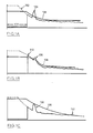
- Figures 1A, 1B and 1C are graphs illustrating the processing of signals received by a transducer following a shot.
- the start point may be set manually by entering a value from the keyboard, or automatically.
- the operator To set the start point automatically, the operator must first ensure that the material level is well down from the transducer, and then by use of the keyboard instruct the computer to calculate a start point which will cause the reference curve to clear the transducer ringing following the blanking interval 100.
- the start point cannot be set with a full bin because the valid close-in echo may appear to be transducer ringing and the start point would be set high to clear this echo 108 (see Figure 1C), with resultant detection of a spurious echo 112.
- the ringing may increase for the following reasons:
- the operator must recognize these factors and set the start point high enough to clear the worst case of expected ringing. If the start point is too high then valid close-in echoes will not be detected. If the start point is set too low then the apparatus may initially operate correctly, but a change of season will probably cause an increase in ringing and the start point must then be increased. If a compromise cannot be achieved then the blanking interval 100 must be increased so that less of the ringing is seen. The disadvantage of increasing the blanking is that levels in the top portion of the bin cannot be measured, and the useful height of the bin is thus reduced.
- transducer performance may vary within a wide range, and that connections to the transducer may pick up electrical noise, makes it difficult reliably to detect defective transducers or transducer wiring.
- a narrow pulse width has the effect of shifting the ringing to the left, when viewed graphically, simply because the end of transmission occurs sooner. The position of the echo remains the same and therefore close-in echoes will stand out more above the ringing.
- a wide transmit pulse has the effect of producing the largest possible return echo, even in the presence of air currents which tend to disperse the sound wave, as often happens with distant targets.
- Objects of this aspect of the present invention thus include the ability to relieve an operator from any involvement in setting the start point or similar parameter, the ability to have the system continuously and automatically compensate for changes in transducer ringing, the ability to automatically adjust the operation of the system so that close-in echo detction is improved without compromising far echo detection, and the ability to detect defective or absent transducers or transducer connections.
- an acoustic ranging system comprising at least one electro-acoustic transducer directed towards the surface of material whose level is to be determined, a transmitter to transmit pulses of high frequency electrical energy to energize selectively each said transducer whereby to cause it to emit at least one shot of high frequency sound, a receiver receiving and amplifying electrical energy from said at least one shot regenerated by said transducer over a subsequent period, the time lapse after a shot before receipt by said receiver of energy regenerated from an echo from said surface being proportional to the distance of the origin of the echo, signal processing means comprising analog to digital converter means to sample repeatedly the output amplitude of the signal from the receiver at defined intervals and to digitize the samples; memory means to store an extended sequence of digitized samples so produced in respect of at least one shot and form therefrom a digital data base depicting an amplitude/time profile of the received signal with a resolution dependent on the sampling intervals; means to
- the transmit pulse will saturate the receiver if the latter is active during the transmit pulse, thus producing signal samples at a reference output level from the latter from which the values of subsequent signal samples must necessarily decline, thus automatically setting a start point for the echo profile.
- a separate test may be made of the samples forming the initial portion of the echo profile, thus enabling even very short range echoes to be detected.
- this initial portion in which the amplitude component of successive samples due to transducer ringing will be declining steeply, it may normally be assumed that any significant upturn in the echo profile can only represent a true echo.
- this separate test reveals no echo, then either the remaining portion of the echo profile may be tested for the presence of echoes as described in U.S. Patent No. 4,596,144, or a further shot may be taken using a broader transmit pulse so as to improve the resolution of distance echoes.
- the diagram shown of a computer unit is a simplified version of that shown in Figure 1 of U.S. Patent No. 4,596,144, with the difference that the keyboard 52 and control keys 58 of that patent are replaced by an infrared receiver 2 associated with an infrared sensor diode 4, and the division of the memory in three rather than two parts, read only memory 6, random access memory 8 and non-volatile memory 10.
- the non-volatile memory may be implemented by a conventional RAM with battery backup, or implemented by RAM chips with integral battery backup, or by electrically alterable and erasable read only memory, or magnetic bubble memory or any other suitable technology combining the ability to retain memory content under power down conditions with the ability to alter memory content under program control.
- the non-volatile memory referred to for convenience as NOVRAM, is utilized for retaining constants which are dependent on a particular installation or configuration or which only require alteration at long intervals, such as configuration and calibration data.
- the read only memory 6 contains a predetermined program which controls a microprocessor 12, which in turn utilizes the random access memory 8 for working memory and temporary storage of variable data, whilst constants other than those predetermined by the program itself are stored in the NOVRAM 10.
- the main portion of the program itself may be essentially as described in U.S. Patent No. 4,596,144 except for amendment to segregate the data addresses utilized appropriately between the memories 8 and 10, and any revision of the routines associated with an interface 14 to the receiver 2 so as to suit it to receive data from such a source rather than a keyboard or control keys.
- the program is however further developed as set forth below with reference to Figure 3, so as to further improve echo detection performance.
- An interface 16 is provided to a transmitter 18 sending pulses to an external ultrasonic transducer 20, and interface 22 with an anlog to digital converter 24 receiving return signals from the transducer 20 via a receiver 26, and from an external temperature sensor 28.
- the transducer 20 and sensor 28 are appropriately mounted in relation to a bin or silo 30 which is being monitored.
- An interface 32 is provided to an alarm relay unit 34, which may drive alarm indicator lamps and possible external alarm devices, whilst an interface 36 drives a digital display 38.
- a further interface 40 drives a digital to analog converter and current source serial data transmitter 42.
- the diode 4 associated with the reciever 2 can receive modulated data from infrared source diode driven by a coding circuit, which causes the diode to emit different pulse trains according to which key of a number of keys on a separate keypad has been depressed.
- the diode, encoder, a battery powering the circuit, and the keypad are incorporated into a small portable calibrator unit which may be constructed similarly and utilizing similar devices, to the infrared remote control units widely used to control domestic appliances such as television sets. It should be understood however, as discussed further below, that the unit is not utilized as a remote control unit in the usual sense.
- the receiver 2 and diode 4 may also be similar to those utilized in remote control receivers and providing digital outputs responsive to key presses applied to a keypad on a transmitter.
- the saturation level 202 of the receiver can then determine the start level of the reference curve, if such is utilized, although in many cases detection of an echo 204 in the first portion of the received signal 206 may be adequately achieved merely by examining this portion for any upturn in the amplitude of the received signal, on the premise that the amplitude of ringing will be dropping sufficiently rapidly over the first portion of the curve that only a wanted echo will have sufficient amplitude to reverse the falling trend. Any change in the amplitude of ringing will neither change the saturation level nor significantly affect the validity of the premise; thus in Figure 4B the level of ringing has increased, but the wanted echo can still be detected.
- some alternative echo identification technique may be necessary; for example blanking of some form may be necessary to eliminate the unwanted echo. If blanking is used, the echo search simply begins at the point in the profile where the blanking would end, the echo profile itself remaining unblanked.
- the shot sequence is complete if a wanted echo has been detected. If no wanted echo has been detected, a second shot is taken using a wider transmit pulse, a first portion of the received signal is disregarded, and the remainder tested for a wanted echo. Since a portion of the signal equivalent to that now disregarded has already been tested for a wanted echo, the portion 208 (see Figure 4C) may be disregarded, thus ensuring that ringing of the transducer has been considerably attenuated even at the commencement of the portion of the signal being analyzed. This facilitates choice of a suitable starting point for a reference curve 210 utilized to select a wanted echo 204.
- the size of sample file or data base to be formed from the received signal is calculated, based upon the range span and resolution required.
- the range span and resolution parameters are stored in NOVRAM or RAM and are fetched utilizing an appropriate subroutine.
- a test is then made of whether an initial interval 208 is greater than 5.76 ms, equivalent to a 1 metre range. If the answer is affirmative, a jump is made to routine SHOT 1, described later. Otherwise the subroutine ATTN is called which turns on an attenuator in the receiver 26 to suit its response, to strong echoes.
- a subroutine FIRE which causes the transmitter to fire a pulse, the duration of which is determined by a parameter (in this case 8) passed in register A of microprocessor 12, and which causes the received signal to be digitized by converter 24. Since only a first portion of the received signal is of interest, only samples relating to this portion are stored in RAM by the subroutine FIRE so as to form a first file.
- the first file is then truncated by the subroutine GRASS to remove data following the point at which the signal level falls below 50 dB, and transferred to a second file where it is processed by the subroutine RECH to select the first echo with a rising edge greater than an amount set by a parameter stored in NOVRAM, and to return in various registers the elapsed time to the echo and various parameters of the echo, and the confidence level that a wanted echo has been detected.
- the confidence level in this instance is considered to be the height of the rising edge of the echo, provided that the echo peak has a predetermined minimum amplitude and the elapsed time corresponds to a range less than 1 metre, failing which a confidence level of zero is returned, indicating failure to detect a wanted echo.
- a test is then made to determine whether a suitable echo was found, failing which execution jumps to subroutine SHOT 1. If an echo was detected, execution jumps to label AGIT discussed further below.
- routine SHOT 1 the subroutine ATTN is again called, but with a different parameter so as to disable the receiver attenuator since the signals of interest will be at a lower level.
- the subroutine FIRE is called, also with passage to a different parameter (40) corresponding to a much longer transmit pulse, in this example five times longer than the short pulse, and an extended range of samples corresponding to the full required span is stored in the first file by the subroutine FIRE.
- the stored data is then filtered by the subroutine NSPK to remove spikes and interference from the data which are of too short a duration to represent valid echoes, and transferred to the second file.
- a reference curve is then formed in the second file utilizing the data from the second file to determine a start point and then form a smoothed curve from which echo information has been filtered by forming running averages of groups of successive samples.
- the second file is then reloaded with the data from the first file, and a first portion of the data is blanked by subroutine BLANK, whereafter the reference curve is then shifted upwardly by a subroutine AHVL so that it intersects the largest echo at midpoint.
- a subroutine FECH selects the earliest echo of sufficient amplitude extending above the reference curve, returning similar data in the same registers as those used by the subroutine RECH.
- "sufficient amplitude" may be some fraction, typically half, of the amplitude of the largest echo.
- the confidence level is considered to be the difference between the selected echo and the next largest echo. In no valid echo is detected, the confidence level is zero.
- This subroutine tests the amplitude of the echo profile stored in memory at a predetermined interval after the commencement of the transmit pulse.
- the transmit pulse is 1 millisecond wide, and the amplitude is tested 2 milliseconds after the commencement of the pulse, i.e. 1 millisecond after the end of the pulse, these timings being of course exemplary. If the stored amplitude which is tested fails to reach a certain threshold level, certain variables are set to zero to indicate that the results of that shot should be ignored and that the transducer to which the transmit pulse was applied is probably defective or out of circuit.
- the effect of the transmit pulse will be to produce an initially rapidly decaying "ringing" of the transducer, which must have a fairly high Q in order to provide reasonable efficiency of operation.
- the timing of the test is preferably such that it is sooner than any echo could normally be expected, and before the ampitude of the ringing has dropped to a level at which it is comparble to noise that may occur in the received signal.
- loss of echo Whilst known ultrasonic level systems frequentivelyly incorporate means indiciate "loss of echo", such loss of echo may arise from various causes such as high noise levels during filling of containers, inability to select betweeen multiple echoes, and short or open circuit faults in the transducer or its connecting cable due to failure or physical damage. Not only are existing systems unable to discriminate between possible causes of loss of echo, but the case of an open or short circuit transducer fault, the connecting cable may still pick up noise which may be mistaken for echoes. This problem is more severe with open circuit faults, but can also occur with short circuit faults in transducers used to monitor low level echoes through long cables.
- the ringing amplitude test described above permits reliable detection of open or short circuit faults, since ringing will be absent or of much reduced amplitude, thus making the loss of echo indication more reliable, and providing warning of faults.
- the test will automatically determine which points have operative transducers, thus enabling transducers to be brought into and taken out of service without reprogramming.
- a subroutine AGIT is then called which stores the echo parameters passed by the subroutine RECH or FECH, and tests the validity of the data. If the confidence level is zero, then previous echo data is retained, and the stored confidence level is set to zero. Otherwise, the echo position is tested against a window containing a previously stored echo position (or such a window is formed if necessary from the new echo), and parameters representing confidence level, echo position, window duration and window starting point are updated in RAM if necessary. The echo time delay is then calculated by subroutine ETD and stored as a further parameter to complete the routine.
- the SHOT routine may then be repeated if necessary, as set forth in U.S. Patent No. 4,596,144.
- the SHOT 1 routine may advantageously be utilized with a medium length transmitted pulse, even without the preceding use of a short pulse if rapid operation is important.
- the SHOT 1 routine is particularly useful in isolating valid echoes in liquid level measurements in tanks where reflections may occur between the liquid and the top of the tank.
- the SHOT 1 routine could be utilized, and if that too produces an apparently valid echo, then a determination could be made as to which was the true echo. This technique may be useful when structural features of the enclosure being monitored tend to result in spurious short range echoes.
- the SHORT routine may be utilized with a signle transmitted pulse, with the subroutine ATTN deleted and the subroutine FIRE omitted from the SHOT 1 routine.
- the principal advantage of using an initial short transmitted pulse to test for short range echoes is that a short pulse advances the point in time at which transducer ringing begins to decay, thus simplifying echo detection at very short ranges.
- a single medium length shot may provide adequate performance, particularly if the sample data base collected in the first file is processed in two stages as described.
Landscapes
- Physics & Mathematics (AREA)
- Engineering & Computer Science (AREA)
- Radar, Positioning & Navigation (AREA)
- Remote Sensing (AREA)
- Computer Networks & Wireless Communication (AREA)
- General Physics & Mathematics (AREA)
- Acoustics & Sound (AREA)
- Electromagnetism (AREA)
- Thermal Sciences (AREA)
- Fluid Mechanics (AREA)
- Measurement Of Velocity Or Position Using Acoustic Or Ultrasonic Waves (AREA)
- Measurement Of Mechanical Vibrations Or Ultrasonic Waves (AREA)
Priority Applications (1)
| Application Number | Priority Date | Filing Date | Title |
|---|---|---|---|
| AT87308783T ATE104442T1 (de) | 1986-10-03 | 1987-10-02 | Akustisches entfernungsmessungssystem. |
Applications Claiming Priority (4)
| Application Number | Priority Date | Filing Date | Title |
|---|---|---|---|
| US06/916,013 US4821215A (en) | 1986-10-03 | 1986-10-03 | Monitoring equipment for adverse environments |
| US916013 | 1986-10-03 | ||
| US07/041,877 US4831565A (en) | 1986-10-03 | 1987-04-22 | Process control equipment for adverse environments |
| US41877 | 1987-04-22 |
Publications (3)
| Publication Number | Publication Date |
|---|---|
| EP0262990A2 true EP0262990A2 (de) | 1988-04-06 |
| EP0262990A3 EP0262990A3 (en) | 1989-10-25 |
| EP0262990B1 EP0262990B1 (de) | 1994-04-13 |
Family
ID=26718644
Family Applications (1)
| Application Number | Title | Priority Date | Filing Date |
|---|---|---|---|
| EP87308783A Expired - Lifetime EP0262990B1 (de) | 1986-10-03 | 1987-10-02 | Akustisches Entfernungsmessungssystem |
Country Status (6)
| Country | Link |
|---|---|
| US (1) | US4831565A (de) |
| EP (1) | EP0262990B1 (de) |
| JP (1) | JP2515803B2 (de) |
| CA (1) | CA1326709C (de) |
| DE (1) | DE3789591T2 (de) |
| ES (1) | ES2051273T3 (de) |
Cited By (13)
| Publication number | Priority date | Publication date | Assignee | Title |
|---|---|---|---|---|
| EP0340953A3 (en) * | 1988-05-05 | 1989-11-23 | Federal Industries Industrial Group Inc. | Acoustic range finding system |
| EP0346044A1 (de) * | 1988-06-09 | 1989-12-13 | Spectra Physics Inc. | Verfahren zum automatischen Regeln der Grabtiefe eines Arbeitsgerätes einer Erdbewegungsmaschine, insbesondere eines Planiergerätes |
| EP0346043A1 (de) * | 1988-06-09 | 1989-12-13 | Spectra Physics Inc. | Verfahren zum automatischen Regeln der Grabtiefe eines Arbeitsgeräts einer Erdbewegungsmaschine, insbesondere eines Planiergeräts |
| EP0349132A1 (de) * | 1988-06-09 | 1990-01-03 | Spectra Physics Inc. | Verfahren zur automatischen Höheneinstellung eines Arbeitsgerätes einer Erdbewegungsmaschine |
| US4992998A (en) * | 1986-10-03 | 1991-02-12 | Federal Industries Industrial Group Inc. | Acoustic range finding system |
| US5184293A (en) * | 1988-06-09 | 1993-02-02 | Spectra Physics | Apparatus for automatic depth control for earth moving and grading |
| US5235511A (en) * | 1988-06-09 | 1993-08-10 | Spectra-Physics, Inc. | Method for automatic depth control for earth moving and grading |
| EP0644404A1 (de) * | 1993-09-16 | 1995-03-22 | Simmonds Precision Products Inc. | Verfahren und Vorrichtung zur Unterscheidung zwischen echten und falschen Ultraschallechos |
| GB2306003A (en) * | 1995-10-02 | 1997-04-23 | Federal Ind Ind Group Inc | Vibrating level detector for solids |
| WO2002035190A1 (fr) * | 2000-10-25 | 2002-05-02 | Zhi Lu | Procede permettant de mesurer un niveau de liquide dans des reservoirs d'huile de grande dimension en faisant intervenir des ondes ultrasonores |
| EP1918735A1 (de) | 2006-10-31 | 2008-05-07 | Siemens Milltronics Process Instruments Inc. | Verfahren zur Verarbeitung eines Echoprofils |
| WO2008080840A1 (de) * | 2006-12-29 | 2008-07-10 | Endress+Hauser Gmbh+Co.Kg | Verfahren zur ermittlung und überwachung des füllstands eines mediums in einem behälter nach einem laufzeitmessverfahren |
| EP3196945B1 (de) | 2016-01-20 | 2019-06-19 | Lg Electronics Inc. | Solarzelle |
Families Citing this family (24)
| Publication number | Priority date | Publication date | Assignee | Title |
|---|---|---|---|---|
| GB2242023B (en) * | 1990-03-14 | 1993-09-08 | Federal Ind Ind Group Inc | Improvements in acoustic ranging systems |
| US5131271A (en) * | 1990-04-16 | 1992-07-21 | Magnetrol International, Inc. | Ultrasonic level detector |
| US5335545A (en) * | 1990-09-04 | 1994-08-09 | Magnetrol International, Inc. | Ultrasonic detector with frequency matching |
| AU2658192A (en) * | 1991-09-30 | 1993-05-03 | Milltronics Ltd. | Calibration system for measurement instruments |
| US5267219A (en) * | 1992-07-17 | 1993-11-30 | Milltronics Ltd. | Acoustic range-finding system |
| US5416723A (en) * | 1993-03-03 | 1995-05-16 | Milltronics Ltd. | Loop powered process control transmitter |
| US5453932A (en) * | 1994-01-12 | 1995-09-26 | Advanced Grade Technology, Inc. | Device and method for detecting and elimination of spurious ultrasonic ranging echoes |
| DE29609646U1 (de) * | 1996-05-31 | 1996-08-14 | Technische Universität Dresden, 01069 Dresden | Vorrichtung zur dynamischen Messung der Oberflächenspannung einer Flüssigkeit |
| US5943294A (en) * | 1997-04-08 | 1999-08-24 | Milltronics Ltd. | Level detector for fluent material |
| US6263989B1 (en) | 1998-03-27 | 2001-07-24 | Irobot Corporation | Robotic platform |
| GB2342995B (en) | 1998-10-21 | 2003-02-19 | Federal Ind Ind Group Inc | Improvements in pulse-echo measurement systems |
| US6341271B1 (en) | 1998-11-13 | 2002-01-22 | General Electric Company | Inventory management system and method |
| US6421811B1 (en) * | 1999-09-30 | 2002-07-16 | Advanced Micro Devices, Inc. | Defect detection via acoustic analysis |
| US6430728B1 (en) * | 1999-09-30 | 2002-08-06 | Advanced Micro Devices, Inc. | Acoustic 3D analysis of circuit structures |
| US6870792B2 (en) | 2000-04-04 | 2005-03-22 | Irobot Corporation | Sonar Scanner |
| US6460412B1 (en) | 2000-10-27 | 2002-10-08 | Union Carbide Chemicals & Plastics Technology Corporation | Detection of dynamic fluidized bed level in a fluidized bed polymerization reactor using ultrasonic waves or microwaves |
| US6795319B2 (en) * | 2001-03-20 | 2004-09-21 | Siemens Milltronics Process Instruments, Inc. | Intrinsically safe portable programmer for enclosed electronic process control equipment |
| US7259712B1 (en) | 2004-09-30 | 2007-08-21 | Siemens Milltronics Process Instruments Inc. | Antenna with integral sealing member for a radar-based level measurement system |
| EP1785699B1 (de) * | 2005-11-09 | 2012-06-27 | Siemens Aktiengesellschaft | Impulsechosystem zum Erfassen eines Flüssigkeitsstands |
| DE602007011241D1 (de) * | 2007-06-19 | 2011-01-27 | Ford Global Tech Llc | Hybridfahrzeug, Antriebssystem für ein Hybridfahrzeug und Verfahren für eine Abgasverarbeitungsvorrichtung in einem solchen System |
| EP2108976B1 (de) * | 2008-04-10 | 2012-10-03 | Siemens Aktiengesellschaft | Verfahren zur Verarbeitung von Echoprofilen und Puls-Echosystem zur Verwendung mit dem Verfahren |
| EP2372318B1 (de) * | 2010-03-26 | 2020-03-18 | VEGA Grieshaber KG | Störechospeicherung bei Behälterrauschen |
| US9423493B2 (en) * | 2013-03-15 | 2016-08-23 | Semiconductor Components Industries, Llc | Method of forming a transducer controller and apparatus therefrom |
| US11372093B2 (en) * | 2018-09-14 | 2022-06-28 | Fujifilm Sonosite, Inc. | Automated fault detection and correction in an ultrasound imaging system |
Family Cites Families (15)
| Publication number | Priority date | Publication date | Assignee | Title |
|---|---|---|---|---|
| US3944965A (en) * | 1965-01-22 | 1976-03-16 | The United States Of America As Represented By The Secretary Of The Navy | Overflow threshold control for sonar |
| DE1566852C3 (de) * | 1967-10-12 | 1974-02-07 | Fried. Krupp Gmbh, 4300 Essen | Anordnung zur Unterscheidung von Echolotimpulsen |
| US3896411A (en) * | 1974-02-19 | 1975-07-22 | Westinghouse Electric Corp | Reverberation condition adaptive sonar receiving system and method |
| US4000650B1 (en) * | 1975-03-20 | 1995-11-14 | Endress Hauser Gmbh Co | Method and apparatus for ultrasonic material level measurement |
| US4222275A (en) * | 1978-10-02 | 1980-09-16 | Dapco Industries, Inc. | System for non-destructively acquiring and processing information about a test piece |
| US4330174A (en) * | 1980-03-20 | 1982-05-18 | Douglass Howard S | Fail-safe fiber optic pushbuttons, displays, and systems employing the same |
| US4436431A (en) * | 1981-05-11 | 1984-03-13 | William A. Strong | Slurry production system |
| FR2551741B1 (fr) * | 1983-09-13 | 1986-04-11 | Aster Boutillon Volucompteurs | Dispositif de commande du mode de fonctionnement d'un distributeur d'hydrocarbure a calculateur electronique |
| DE3339984A1 (de) * | 1983-11-04 | 1985-05-23 | Endress U. Hauser Gmbh U. Co, 7867 Maulburg | Schall- bzw. ultraschall-entfernungsmessgeraet |
| DE3438045C2 (de) * | 1983-11-04 | 1986-12-18 | Endress U. Hauser Gmbh U. Co, 7867 Maulburg | Anordnung zur Signalübertragung bei Ultraschall-Echolotgeräten |
| DE3418486C1 (de) * | 1984-05-18 | 1986-01-02 | Krautkrämer GmbH, 5000 Köln | Ultraschallprüfverfahren und Schaltungsvorrichtung zur automatischen Ermittlung von rückwandnahen Ungänzen |
| GB8422022D0 (en) * | 1984-08-31 | 1984-10-24 | Atomic Energy Authority Uk | Electrical signal discrimination |
| CA1214858A (en) * | 1984-09-27 | 1986-12-02 | Stanley Panton | Acoustic ranging system |
| GB8426964D0 (en) * | 1984-10-25 | 1984-11-28 | Sieger Ltd | Adjusting circuit parameter |
| US4703359A (en) * | 1985-05-30 | 1987-10-27 | Nap Consumer Electronics Corp. | Universal remote control unit with model identification capability |
-
1987
- 1987-04-22 US US07/041,877 patent/US4831565A/en not_active Expired - Lifetime
- 1987-05-29 JP JP62134755A patent/JP2515803B2/ja not_active Expired - Lifetime
- 1987-08-31 CA CA000545756A patent/CA1326709C/en not_active Expired - Fee Related
- 1987-10-02 ES ES87308783T patent/ES2051273T3/es not_active Expired - Lifetime
- 1987-10-02 EP EP87308783A patent/EP0262990B1/de not_active Expired - Lifetime
- 1987-10-02 DE DE3789591T patent/DE3789591T2/de not_active Expired - Lifetime
Cited By (21)
| Publication number | Priority date | Publication date | Assignee | Title |
|---|---|---|---|---|
| US4992998A (en) * | 1986-10-03 | 1991-02-12 | Federal Industries Industrial Group Inc. | Acoustic range finding system |
| JPH0262992A (ja) * | 1988-05-05 | 1990-03-02 | Federal Ind Ind Group Inc | 音響測距装置 |
| EP0340953A3 (en) * | 1988-05-05 | 1989-11-23 | Federal Industries Industrial Group Inc. | Acoustic range finding system |
| EP0346044A1 (de) * | 1988-06-09 | 1989-12-13 | Spectra Physics Inc. | Verfahren zum automatischen Regeln der Grabtiefe eines Arbeitsgerätes einer Erdbewegungsmaschine, insbesondere eines Planiergerätes |
| EP0346043A1 (de) * | 1988-06-09 | 1989-12-13 | Spectra Physics Inc. | Verfahren zum automatischen Regeln der Grabtiefe eines Arbeitsgeräts einer Erdbewegungsmaschine, insbesondere eines Planiergeräts |
| EP0349132A1 (de) * | 1988-06-09 | 1990-01-03 | Spectra Physics Inc. | Verfahren zur automatischen Höheneinstellung eines Arbeitsgerätes einer Erdbewegungsmaschine |
| US4924374A (en) * | 1988-06-09 | 1990-05-08 | Spectra Physics | Method for automatic position control of a tool |
| US5184293A (en) * | 1988-06-09 | 1993-02-02 | Spectra Physics | Apparatus for automatic depth control for earth moving and grading |
| US5235511A (en) * | 1988-06-09 | 1993-08-10 | Spectra-Physics, Inc. | Method for automatic depth control for earth moving and grading |
| US6046960A (en) * | 1993-09-16 | 2000-04-04 | Simmonds Precision Products, Inc. | Apparatus and method for discriminating true and false ultrasonic echoes |
| EP0644404A1 (de) * | 1993-09-16 | 1995-03-22 | Simmonds Precision Products Inc. | Verfahren und Vorrichtung zur Unterscheidung zwischen echten und falschen Ultraschallechos |
| GB2306003A (en) * | 1995-10-02 | 1997-04-23 | Federal Ind Ind Group Inc | Vibrating level detector for solids |
| GB2306003B (en) * | 1995-10-02 | 1999-09-29 | Federal Ind Ind Group Inc | Level detector for solids |
| US5748562A (en) * | 1995-10-02 | 1998-05-05 | Milltronics Ltd. | Level detector for solids |
| WO2002035190A1 (fr) * | 2000-10-25 | 2002-05-02 | Zhi Lu | Procede permettant de mesurer un niveau de liquide dans des reservoirs d'huile de grande dimension en faisant intervenir des ondes ultrasonores |
| EP1918735A1 (de) | 2006-10-31 | 2008-05-07 | Siemens Milltronics Process Instruments Inc. | Verfahren zur Verarbeitung eines Echoprofils |
| US7420877B2 (en) | 2006-10-31 | 2008-09-02 | Siemens Milltronics Process Instruments, Inc. | Method for processing an echo profile |
| WO2008080840A1 (de) * | 2006-12-29 | 2008-07-10 | Endress+Hauser Gmbh+Co.Kg | Verfahren zur ermittlung und überwachung des füllstands eines mediums in einem behälter nach einem laufzeitmessverfahren |
| US8276444B2 (en) | 2006-12-29 | 2012-10-02 | Endress + Hauser Gmbh + Co. Kg | Method for ascertaining and monitoring fill level of a medium in a container using a travel time, measuring method |
| CN101573596B (zh) * | 2006-12-29 | 2013-09-11 | 恩德莱斯和豪瑟尔两合公司 | 用于根据渡越时间测量方法确定及监控容器中的介质的料位的方法 |
| EP3196945B1 (de) | 2016-01-20 | 2019-06-19 | Lg Electronics Inc. | Solarzelle |
Also Published As
| Publication number | Publication date |
|---|---|
| EP0262990A3 (en) | 1989-10-25 |
| CA1326709C (en) | 1994-02-01 |
| US4831565A (en) | 1989-05-16 |
| JPS63139273A (ja) | 1988-06-11 |
| DE3789591D1 (de) | 1994-05-19 |
| JP2515803B2 (ja) | 1996-07-10 |
| EP0262990B1 (de) | 1994-04-13 |
| DE3789591T2 (de) | 1994-08-25 |
| ES2051273T3 (es) | 1994-06-16 |
Similar Documents
| Publication | Publication Date | Title |
|---|---|---|
| EP0262990B1 (de) | Akustisches Entfernungsmessungssystem | |
| US5319972A (en) | Ultrasonic liquid level measurement system | |
| US4890266A (en) | Acoustic range finding system | |
| US4596144A (en) | Acoustic ranging system | |
| US4700569A (en) | Method and arrangement for signal transmission in ultrasonic echo sounding systems | |
| US4992998A (en) | Acoustic range finding system | |
| US6298008B1 (en) | Pulse-echo system for mediums having varying densities | |
| US5150334A (en) | System and method for ultrasonic measurement of material level | |
| US5260912A (en) | Side-looking fish finder | |
| US5157639A (en) | Ultrasonic detector | |
| US6046960A (en) | Apparatus and method for discriminating true and false ultrasonic echoes | |
| US5682134A (en) | Method of operating a device for monitoring the interior of an automotive vehicle | |
| US4482889A (en) | Device for detecting failure of ultrasonic apparatus | |
| JPS6298286A (ja) | 水中の反射体の音波反射係数を測定するシステム | |
| US4170143A (en) | Recognizing ultrasonic response signals during testing of structural materials | |
| KR850006755A (ko) | 반사된 신호를 처리하는 방법 및 장치 | |
| GB2230608A (en) | Acoustic range finder for monitoring level of material | |
| EP0174090B1 (de) | Diskriminierung von elektrischen Signalen | |
| AU598116B2 (en) | Acoustic range finding system | |
| JPS56164953A (en) | Ultrasonic inspecting device for junction part | |
| US4414849A (en) | Apparatus and a method for indicating variations in acoustic properties on an interface | |
| CA1122693A (en) | Ultrasonic testing of welds in wheels | |
| JPS6161072B2 (de) | ||
| CA1154140A (en) | Echo recognition system | |
| US4581937A (en) | Method of suppressing unwanted indications in automated ultrasonic testing |
Legal Events
| Date | Code | Title | Description |
|---|---|---|---|
| PUAI | Public reference made under article 153(3) epc to a published international application that has entered the european phase |
Free format text: ORIGINAL CODE: 0009012 |
|
| AK | Designated contracting states |
Kind code of ref document: A2 Designated state(s): AT BE CH DE ES FR GB GR IT LI LU NL SE |
|
| RAP1 | Party data changed (applicant data changed or rights of an application transferred) |
Owner name: FEDERAL INDUSTRIES INDUSTRIAL GROUP INC. |
|
| PUAL | Search report despatched |
Free format text: ORIGINAL CODE: 0009013 |
|
| AK | Designated contracting states |
Kind code of ref document: A3 Designated state(s): AT BE CH DE ES FR GB GR IT LI LU NL SE |
|
| 17P | Request for examination filed |
Effective date: 19891015 |
|
| 17Q | First examination report despatched |
Effective date: 19901130 |
|
| RAP1 | Party data changed (applicant data changed or rights of an application transferred) |
Owner name: MILLTRONICS LTD. |
|
| GRAA | (expected) grant |
Free format text: ORIGINAL CODE: 0009210 |
|
| RAP1 | Party data changed (applicant data changed or rights of an application transferred) |
Owner name: MILLTRONICS LTD. |
|
| AK | Designated contracting states |
Kind code of ref document: B1 Designated state(s): AT BE CH DE ES FR GB GR IT LI LU NL SE |
|
| PG25 | Lapsed in a contracting state [announced via postgrant information from national office to epo] |
Ref country code: LI Effective date: 19940413 Ref country code: GR Free format text: LAPSE BECAUSE OF FAILURE TO SUBMIT A TRANSLATION OF THE DESCRIPTION OR TO PAY THE FEE WITHIN THE PRESCRIBED TIME-LIMIT Effective date: 19940413 Ref country code: CH Effective date: 19940413 Ref country code: AT Effective date: 19940413 |
|
| REF | Corresponds to: |
Ref document number: 104442 Country of ref document: AT Date of ref document: 19940415 Kind code of ref document: T |
|
| REF | Corresponds to: |
Ref document number: 3789591 Country of ref document: DE Date of ref document: 19940519 |
|
| REG | Reference to a national code |
Ref country code: ES Ref legal event code: FG2A Ref document number: 2051273 Country of ref document: ES Kind code of ref document: T3 |
|
| ITF | It: translation for a ep patent filed | ||
| REG | Reference to a national code |
Ref country code: CH Ref legal event code: PL |
|
| ET | Fr: translation filed | ||
| PG25 | Lapsed in a contracting state [announced via postgrant information from national office to epo] |
Ref country code: LU Free format text: LAPSE BECAUSE OF NON-PAYMENT OF DUE FEES Effective date: 19941031 |
|
| EAL | Se: european patent in force in sweden |
Ref document number: 87308783.7 |
|
| PLBE | No opposition filed within time limit |
Free format text: ORIGINAL CODE: 0009261 |
|
| STAA | Information on the status of an ep patent application or granted ep patent |
Free format text: STATUS: NO OPPOSITION FILED WITHIN TIME LIMIT |
|
| 26N | No opposition filed | ||
| PGFP | Annual fee paid to national office [announced via postgrant information from national office to epo] |
Ref country code: ES Payment date: 19981029 Year of fee payment: 12 |
|
| PGFP | Annual fee paid to national office [announced via postgrant information from national office to epo] |
Ref country code: BE Payment date: 19981109 Year of fee payment: 12 |
|
| PG25 | Lapsed in a contracting state [announced via postgrant information from national office to epo] |
Ref country code: ES Free format text: LAPSE BECAUSE OF NON-PAYMENT OF DUE FEES Effective date: 19991003 |
|
| PG25 | Lapsed in a contracting state [announced via postgrant information from national office to epo] |
Ref country code: BE Free format text: LAPSE BECAUSE OF NON-PAYMENT OF DUE FEES Effective date: 19991031 |
|
| BERE | Be: lapsed |
Owner name: MILLTRONICS LTD Effective date: 19991031 |
|
| PGFP | Annual fee paid to national office [announced via postgrant information from national office to epo] |
Ref country code: SE Payment date: 20001017 Year of fee payment: 14 |
|
| PGFP | Annual fee paid to national office [announced via postgrant information from national office to epo] |
Ref country code: NL Payment date: 20001031 Year of fee payment: 14 |
|
| PG25 | Lapsed in a contracting state [announced via postgrant information from national office to epo] |
Ref country code: SE Free format text: LAPSE BECAUSE OF NON-PAYMENT OF DUE FEES Effective date: 20011003 |
|
| REG | Reference to a national code |
Ref country code: GB Ref legal event code: IF02 |
|
| PG25 | Lapsed in a contracting state [announced via postgrant information from national office to epo] |
Ref country code: NL Free format text: LAPSE BECAUSE OF NON-PAYMENT OF DUE FEES Effective date: 20020501 |
|
| EUG | Se: european patent has lapsed |
Ref document number: 87308783.7 |
|
| NLV4 | Nl: lapsed or anulled due to non-payment of the annual fee |
Effective date: 20020501 |
|
| REG | Reference to a national code |
Ref country code: GB Ref legal event code: 732E |
|
| REG | Reference to a national code |
Ref country code: FR Ref legal event code: TP Ref country code: FR Ref legal event code: CA |
|
| PGFP | Annual fee paid to national office [announced via postgrant information from national office to epo] |
Ref country code: FR Payment date: 20031024 Year of fee payment: 17 |
|
| REG | Reference to a national code |
Ref country code: ES Ref legal event code: FD2A Effective date: 20001113 |
|
| PG25 | Lapsed in a contracting state [announced via postgrant information from national office to epo] |
Ref country code: FR Free format text: LAPSE BECAUSE OF NON-PAYMENT OF DUE FEES Effective date: 20050630 |
|
| REG | Reference to a national code |
Ref country code: FR Ref legal event code: ST |
|
| PG25 | Lapsed in a contracting state [announced via postgrant information from national office to epo] |
Ref country code: IT Free format text: LAPSE BECAUSE OF NON-PAYMENT OF DUE FEES;WARNING: LAPSES OF ITALIAN PATENTS WITH EFFECTIVE DATE BEFORE 2007 MAY HAVE OCCURRED AT ANY TIME BEFORE 2007. THE CORRECT EFFECTIVE DATE MAY BE DIFFERENT FROM THE ONE RECORDED. Effective date: 20051002 |
|
| PGFP | Annual fee paid to national office [announced via postgrant information from national office to epo] |
Ref country code: GB Payment date: 20061012 Year of fee payment: 20 |
|
| PGFP | Annual fee paid to national office [announced via postgrant information from national office to epo] |
Ref country code: DE Payment date: 20061214 Year of fee payment: 20 |
|
| REG | Reference to a national code |
Ref country code: GB Ref legal event code: PE20 |
|
| PG25 | Lapsed in a contracting state [announced via postgrant information from national office to epo] |
Ref country code: GB Free format text: LAPSE BECAUSE OF EXPIRATION OF PROTECTION Effective date: 20071001 |