EP0263037A2 - Appareil d'images de fluorescence à plusieurs temps d'amortissement et procédé de résolution du rapport spatial avec l'appareil - Google Patents
Appareil d'images de fluorescence à plusieurs temps d'amortissement et procédé de résolution du rapport spatial avec l'appareil Download PDFInfo
- Publication number
- EP0263037A2 EP0263037A2 EP87420132A EP87420132A EP0263037A2 EP 0263037 A2 EP0263037 A2 EP 0263037A2 EP 87420132 A EP87420132 A EP 87420132A EP 87420132 A EP87420132 A EP 87420132A EP 0263037 A2 EP0263037 A2 EP 0263037A2
- Authority
- EP
- European Patent Office
- Prior art keywords
- dyes
- dye
- sample
- decay
- detector
- Prior art date
- Legal status (The legal status is an assumption and is not a legal conclusion. Google has not performed a legal analysis and makes no representation as to the accuracy of the status listed.)
- Granted
Links
Images
Classifications
-
- G—PHYSICS
- G01—MEASURING; TESTING
- G01N—INVESTIGATING OR ANALYSING MATERIALS BY DETERMINING THEIR CHEMICAL OR PHYSICAL PROPERTIES
- G01N21/00—Investigating or analysing materials by the use of optical means, i.e. using sub-millimetre waves, infrared, visible or ultraviolet light
- G01N21/62—Systems in which the material investigated is excited whereby it emits light or causes a change in wavelength of the incident light
- G01N21/63—Systems in which the material investigated is excited whereby it emits light or causes a change in wavelength of the incident light optically excited
- G01N21/64—Fluorescence; Phosphorescence
- G01N21/6408—Fluorescence; Phosphorescence with measurement of decay time, time resolved fluorescence
-
- G—PHYSICS
- G01—MEASURING; TESTING
- G01N—INVESTIGATING OR ANALYSING MATERIALS BY DETERMINING THEIR CHEMICAL OR PHYSICAL PROPERTIES
- G01N21/00—Investigating or analysing materials by the use of optical means, i.e. using sub-millimetre waves, infrared, visible or ultraviolet light
- G01N21/17—Systems in which incident light is modified in accordance with the properties of the material investigated
- G01N2021/178—Methods for obtaining spatial resolution of the property being measured
-
- G—PHYSICS
- G01—MEASURING; TESTING
- G01N—INVESTIGATING OR ANALYSING MATERIALS BY DETERMINING THEIR CHEMICAL OR PHYSICAL PROPERTIES
- G01N21/00—Investigating or analysing materials by the use of optical means, i.e. using sub-millimetre waves, infrared, visible or ultraviolet light
- G01N21/62—Systems in which the material investigated is excited whereby it emits light or causes a change in wavelength of the incident light
- G01N21/63—Systems in which the material investigated is excited whereby it emits light or causes a change in wavelength of the incident light optically excited
- G01N21/64—Fluorescence; Phosphorescence
- G01N21/6408—Fluorescence; Phosphorescence with measurement of decay time, time resolved fluorescence
- G01N2021/641—Phosphorimetry, gated
-
- G—PHYSICS
- G01—MEASURING; TESTING
- G01N—INVESTIGATING OR ANALYSING MATERIALS BY DETERMINING THEIR CHEMICAL OR PHYSICAL PROPERTIES
- G01N21/00—Investigating or analysing materials by the use of optical means, i.e. using sub-millimetre waves, infrared, visible or ultraviolet light
- G01N21/62—Systems in which the material investigated is excited whereby it emits light or causes a change in wavelength of the incident light
- G01N21/63—Systems in which the material investigated is excited whereby it emits light or causes a change in wavelength of the incident light optically excited
- G01N21/64—Fluorescence; Phosphorescence
- G01N21/6408—Fluorescence; Phosphorescence with measurement of decay time, time resolved fluorescence
- G01N2021/6413—Distinction short and delayed fluorescence or phosphorescence
-
- G—PHYSICS
- G01—MEASURING; TESTING
- G01N—INVESTIGATING OR ANALYSING MATERIALS BY DETERMINING THEIR CHEMICAL OR PHYSICAL PROPERTIES
- G01N21/00—Investigating or analysing materials by the use of optical means, i.e. using sub-millimetre waves, infrared, visible or ultraviolet light
- G01N21/62—Systems in which the material investigated is excited whereby it emits light or causes a change in wavelength of the incident light
- G01N21/63—Systems in which the material investigated is excited whereby it emits light or causes a change in wavelength of the incident light optically excited
- G01N21/64—Fluorescence; Phosphorescence
- G01N2021/6417—Spectrofluorimetric devices
- G01N2021/6421—Measuring at two or more wavelengths
-
- G—PHYSICS
- G01—MEASURING; TESTING
- G01N—INVESTIGATING OR ANALYSING MATERIALS BY DETERMINING THEIR CHEMICAL OR PHYSICAL PROPERTIES
- G01N21/00—Investigating or analysing materials by the use of optical means, i.e. using sub-millimetre waves, infrared, visible or ultraviolet light
- G01N21/62—Systems in which the material investigated is excited whereby it emits light or causes a change in wavelength of the incident light
- G01N21/63—Systems in which the material investigated is excited whereby it emits light or causes a change in wavelength of the incident light optically excited
- G01N21/64—Fluorescence; Phosphorescence
- G01N21/645—Specially adapted constructive features of fluorimeters
- G01N21/6456—Spatial resolved fluorescence measurements; Imaging
- G01N21/6458—Fluorescence microscopy
-
- G—PHYSICS
- G01—MEASURING; TESTING
- G01N—INVESTIGATING OR ANALYSING MATERIALS BY DETERMINING THEIR CHEMICAL OR PHYSICAL PROPERTIES
- G01N2201/00—Features of devices classified in G01N21/00
- G01N2201/06—Illumination; Optics
- G01N2201/064—Stray light conditioning
- G01N2201/0648—Shutters
Definitions
- This invention relates to fluorescence microscopy in which magnified images of tissues, cells or other components of a sample are obtained from light emission from a plurality of fluorescent dyes which can be attached to specific components or features of the sample.
- Fluorescence microscopy is presently preferred because of its superior image contrast over that of conventional light scattering microscopy and because of the now well established procedure of attaching a wide variety of dyes to target related components which allows for high resolution visualization of structure-specific bindings resulting in rapid growth of an important sub-field of immunocytology.
- time resolved fluorescence is an effective technique for interpreting dynamical interactions with the environment of the dye site and for obtaining information from non-single exponential decay modes.
- time resolved fluorescence has not been suggested or used for non-interfering particular spatial site selection with the exception of long decay time dyes for generalized background differentiation.
- Fluorescent dyes are not the only possible site specific labels that can be used in association with present day imaging techniques. Others include shape and opacity defined labels such as latex particles, collodial gold and thorium particles, india ink, magnetite, erythrocytes and bacteria. Some of these serve purposes beyond imaging such as magnetite tagging which lends itself to separation processes and the like. In addition, there exist substrate imaging techniques such as insoluble substrate deposits and site specific alkaline etching, chemiluminescent stains and radioisotope stains which, although they provide imaging, are again limited to at most two labels simultaneously even when used in a high resolution system.
- a further object of the present invention is to record simultaneously from a single sample high resolution separately distinguishable correlated images from a plurality of excited dyes selected to span a large non-interferring range of decay times.
- Another object of the present invention is to resolve accurately complex mixtures of micro-organisms, and the like.
- Still another object of the present invention is to provide a multi-chronal fluorescence imaging technique for detecting a large number of fluorescent labels and stains which can be readily adapted to such techniques as automatic screening, time lapse photography, cinematography, computerized identification and computer translated multicolor display.
- a multi-chronal fluorescence imaging technique for resolving simultaneously the spatial distribution of a plurality of site specific dyes while, at the same time, eliminating non specific background.
- the sample components are labelled by a battery of dyes that have a relatively large spread of fluorescence decay times.
- the stained or tagged sample components are detected and/or recorded using a high contrast imaging system.
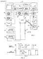
- Fig. l there is shown a schematic representation of a multi-chronal fluorescence microscope, generally referenced l0, which embodies the teachings of the present invention.
- the microscope includes a transparent sample holder ll which is situated in the object plane l2 of a lens barrel l3.
- the lens barrel contains an objective lens l4 and a further lens system l5 for focusing an image of a specimen l6 in the viewing plane of an image detector l7.
- a gate l8 Positioned between the lens barrel and the detector is a gate l8 that contains an electrically actuated shutter that can be precisely opened and closed at timed intervals to permit an image of the sample to be transmitted to the detector for viewing and/or recording.
- a barrier filter l9 is placed in the optical path of the lens system which serves to prevent unwanted background from reaching the detector.
- the sample mounted in the sample holder typically will contain different components of a biological, inorganic or organic nature to which site specific fluorescent dyes can be attached to tag or label particular sample components. Accordingly, a mixed population of cells, for example, may be stained so that particular cells in the mix will take up a fluorescent dye having a specific emission characteristic that can be easily distinguished.
- a plurality of dyes, each having different emission characteristics are added to the sample and are excited simultaneously by ultra-violet light from a pulsed laser 20.
- the light is transmitted to the sample by a flexible fiber optic bundle 2l which can be selectively positioned to direct a beam of irradiating light from above or below the transparent holder.
- a beam controller 23 is mounted in the bundle which can be adjusted to shape the size and intensity profile of the light beam to irradiate uniformly all or a selected portion of the sample.
- the traditional epifluorescent irradiation mode in which excitation light enters the sample via a dichroic mirror and through the objective lens, which in this case must be made of quartz or some other ultra-violet transmitting material, is also adaptable to our multichronal fluorescent microscope.
- the ultraviolet light source 20 is a tunable dye pulsed nitrogen (N2) laser that produces an output beam of radiation that is concentrated about a desired band of radiation at which the dyes readily absorb energy and become excited.
- N2 tunable dye pulsed nitrogen
- PRA Photochemical Research Associates
- the laser is capable of producing output pulses having pulse widths of less than one nanosecond (ns), a command jitter less than two ns, and a maximum repetition rate of l00 Hz.
- the laser is fired in response to a pair of input trigger pulses provided by a first delayed pulse generator 25.
- a compensating variable delay 22 is placed in one of the input trigger lines.
- a Hewlett Packard generator Model 2l4A having a variable delay range between 400 ns and about l0 milliseconds (ms) may be used to trigger the laser 20.
- a second delayed pulse generator 27 of similar construction is used to trigger the gate l8 in timed relation to the firing of the laser.
- the gate l8 is connected to a high voltage pulse generator 30 by means of a pulse forming network 3l.
- a high voltage power supply 32 is connected to that pulse generator and provides sufficient voltage to open and close the gate.
- a synchronous clock generator 33 is turned on by the second delayed pulse generator which applies a l000 V pulse.
- a trigger control unit 34 containing a thyratron acts as a fast response switch in the pulse generating network.
- Gate l8 is a Kerr cell manufactured by the Kappa Corporation. The cell is arranged to produce a pair of cross-polarized, electro-optical fields that can be rapidly rotated to selectively pass and block incoming light. In the present system, the cell acts as a shutter to pass light from the sample to the detector during predetermined periods of time so that the detector can view each excited dye when it is at about its maximum output intensity.
- the opening and closing of the gate l8 is delayed by means of the noted second delayed pulse generator 27 until sometime after the laser has fired.
- sufficient time is provided after the firing of the laser to permit the sample dyes to absorb the exciting radiation and in turn begin to emit fluorescent radiation characteristic of each specific dye.
- the second delayed pulse generator 27 is preprogrammed to open and close the shutter at closely controlled intervals so that time resolved images produced by the dyes can be viewed or recorded simultaneously.
- the present microscope can differentiate between seven or more dyes, its operation will be explained in regard to four specific dyes A-D which have been added to sample l6.
- the dyes each have equal absorptive characteristics and emission quantum efficiencies.
- the dyes are selected so that they exhibit relatively large differences in decay times with the decay time of each dye being separated from its faster or slower neighbor by a factor of about ten.
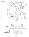
- Fig. 2 there is shown a log-log plot illustrating the decay characteristics of the four dyes A-D after the sample has been initially irradiated with ultraviolet light.
- Dye A which is represented by curve 40 reaches the highest maximum intensity output and accordingly is the first to decay. Decay to a level of about l% its maximum intensity is reached about 46 ns after the light pulse is terminated.
- Dye B as represented by curve 4l, reaches a lower maximum output intensity (one-tenth that of dye A), finally decaying to its l% maximum intensity level at about 460 ns.
- dyes C and D depicted by curves 42 and 43 respectively yield progressively lower maximum output intensities and have correspondingly longer lifetimes to reach their respective l% maximum intensity levels, attaining these at 4.6 ⁇ s and 46 ⁇ s.
- the shutter of the gate l8 can be programmed to open by the delayed pulse generator 27 at intervals of about 0-8 ns, 60-80 ns, 600-800 ns and 6-8 microseconds after the exciting pulse has been terminated.
- the gate opening intervals are schematically depicted in Fig. 2 at positions 45-48.
- the gate is controlled so that the detector scans the irradiated sample in one of the two available modes to produce a rapid, repetitive flickering long term image of each of the dye emissions. Addition of further dyes having shorter decay times is feasible provided the gate switching circuitry is sufficiently fast to handle the increase. Use of dyes having longer decay times is also feasible, but at lower repetitive gate cycles. On-off transmission factors having a ratio of about l0 have been found satisfactory for most dye systems using up to seven dyes.
- Fig. 3 One contemplated scanning mode is illustrated graphically in Fig. 3.
- the laser is adjusted to produce a pulse 50 having a width or duration of time t . This duration is shorter than the decay time of dye A, the dye having the shortest lifetime.
- the delayed pulse generator 25 is further programmed to fire the laser repeatedly at timed intervals t2 which are longer than the decay time of dye D which has the longest lifetime.
- the gate is programmed through the second delayed pulse generator at a time delay t after the termination of each excitation pulse. In this case the system has been programmed to view an image of dye A between the first and second irradiating pulse.
- the gate is opened at some time earlier than 8 ns, the opening gate time being less critical for the shortest decay dye than for the others, and remains open for an interval of about 2 ns.
- dye A is at about its maximum output at this time and because of its relatively high intensity the image masks that of the other dyes which are also radiating at this time.
- the image of dye A is thus differentiated from the other images and thus selectively viewed by the detector.
- the time t is the discrimination parameter for selecting which dye image will be seen by the detector.
- the time t d of opening is shifted to about 60 ns and can remain open for a period of about 20 ns.
- dye A has fully decayed and the intensity of dye B is now still near its peak value and predominates.
- the detector now sees an image produced by dye B.
- the time t d can be again shifted to about 600 ns and the gate can be held open to view dye C.
- time t d can be moved to 6000 ns and held open for an interval of about 2000 ns to view an image of the last dye in the series which is dye D.
- time t d can be shifted each time the laser fires, for computer stored images, or it can be held for a large number of pulses, enough time for the eye or a camera to record the image, before being shifted. It is also contemplated that the time the gate remains open can be controlled within limits to compensate for differences in the absorptive coefficients of the dyes and/or their varying quantum efficiencies.
- a set of fluorescent dyes having lifetimes that differ in an ascending order by a factor of about ten might be fluorescein ( ⁇ l ns); 3 hydroxyanthranilic acid (ll ns); pyrinobutyric acid (l00 ns); unbelliferone 7-hydroxycoumarin (900 ns) and benzoquinone (200-400 ⁇ s).
- fluorescein ⁇ l ns
- ll ns 3 hydroxyanthranilic acid
- pyrinobutyric acid l00 ns
- unbelliferone 7-hydroxycoumarin 900 ns
- benzoquinone 200-400 ⁇ s
- toluidenylnaphthalene -6-sulfonic acid TNS (0.6-6 ns); acrydine orange (2 ns); perylene (4.5 ns); Zinc cytochrome C (9 ns); l-Anilino-8-naphthalene sulfonate (ANS) (l5 ns); l-Dimethylaminonaphthalene-5-sulfonic acid (DANS) (24 ns); 9-aminoacridine (28 ns); furocoumarin (50 ns); l-pyrenebutyric acid (PBA) l02 ns; plus rhodamine B, rare earth chelates, and others.
- TNS 0.6-6 ns
- perylene 4.5 ns
- Zinc cytochrome C 9 ns
- ANS l-Anilino-8-naphthalene sul
- the detector l7 can include a photographic apparatus for recording an image or series of images on film at the various selected decay times.
- the recorded images can be suitably registered and mapped for light intensity, translated into various easily distinguishable colors and then simultaneously displayed.
- a vidicon detector or simple visual observation can also be employed.
- the detector may be a video system for either displaying the images simultaneously upon a video screen 70 or recording them on a video recorder 7l for delayed playback and/or storage.
- a small camera containing a charge coupled device (CCD) capable of recording an image and converting the image data into an electrical output signal suitable for use in a standard video format.
- CCD charge coupled device
- the electrical signals from the CCD imager 73 are fed through a color translater 74 to a memory 75.
- the images relating to the individual dyes are each color coded to more clearly differentiate visually one image from the other before the data is placed in the memory and displayed.
- the image signals are forwarded from the memory to a video processor 76 and then on to the video screen for viewing and/or to the recorder 7l for storage.
- Fig. 4 there is graphically illustrated a second mode of scanning in which the shutter of the gate l8 s sequentially opened and closed during period 45-48 for the time intervals noted above between each of the recurring irradiating pulses. Accordingly, an image produced by each dye is seen by the detector and is repeatedly updated between the recurring pulses.
- an electrochromic color filter may be gated synchronously with the Kerr cell and placed between the Kerr cell and image detector which permits direct visual viewing of each dye image, each appearing in a color selected by the voltage applied to the electrochromic color-tunable filter.
Landscapes
- Health & Medical Sciences (AREA)
- Nuclear Medicine, Radiotherapy & Molecular Imaging (AREA)
- Physics & Mathematics (AREA)
- Life Sciences & Earth Sciences (AREA)
- Chemical & Material Sciences (AREA)
- Analytical Chemistry (AREA)
- Biochemistry (AREA)
- General Health & Medical Sciences (AREA)
- General Physics & Mathematics (AREA)
- Immunology (AREA)
- Pathology (AREA)
- Investigating, Analyzing Materials By Fluorescence Or Luminescence (AREA)
- Microscoopes, Condenser (AREA)
Applications Claiming Priority (2)
| Application Number | Priority Date | Filing Date | Title |
|---|---|---|---|
| US06/914,367 US4791310A (en) | 1986-10-02 | 1986-10-02 | Fluorescence microscopy |
| US914367 | 1992-07-14 |
Publications (3)
| Publication Number | Publication Date |
|---|---|
| EP0263037A2 true EP0263037A2 (fr) | 1988-04-06 |
| EP0263037A3 EP0263037A3 (en) | 1989-07-26 |
| EP0263037B1 EP0263037B1 (fr) | 1991-11-27 |
Family
ID=25434262
Family Applications (1)
| Application Number | Title | Priority Date | Filing Date |
|---|---|---|---|
| EP87420132A Expired - Lifetime EP0263037B1 (fr) | 1986-10-02 | 1987-05-19 | Appareil d'images de fluorescence à plusieurs temps d'amortissement et procédé de résolution du rapport spatial avec l'appareil |
Country Status (4)
| Country | Link |
|---|---|
| US (1) | US4791310A (fr) |
| EP (1) | EP0263037B1 (fr) |
| JP (1) | JPS63204138A (fr) |
| DE (1) | DE3774826D1 (fr) |
Cited By (7)
| Publication number | Priority date | Publication date | Assignee | Title |
|---|---|---|---|---|
| EP0563998A1 (fr) * | 1992-04-02 | 1993-10-06 | Markus Sauer | Procédé de détection de molecules biologiques, de substances toxiques, de polymèrs de substances pharmaceutiques par spectroscopic laser à résolution temporelle |
| EP0668498A3 (fr) * | 1994-02-16 | 1995-10-25 | Hamamatsu Photonics Kk | Procédé et dispositif pour mesurer le transfert résonnant d'énergie de fluorescence. |
| WO1997019342A1 (fr) * | 1995-11-21 | 1997-05-29 | The Research Foundation Of State University Of New York | Procede et appareil d'identification de fluorophores |
| DE19718016A1 (de) * | 1997-04-29 | 1998-11-05 | Drexhage Karl Heinz | Verfahren zur optischen Detektion von Analytmolekülen in einem natürlichen biologischen Medium |
| EP1653220A3 (fr) * | 2001-05-10 | 2006-08-30 | Yokogawa Electric Corporation | Lecteur de biopuce |
| EP1620713A4 (fr) * | 2003-05-07 | 2007-09-12 | Dakota Technologies Inc | Dispositif et procede multi-dimensionnel a fluorescence pour analyse quantitative rapide et extremement sensible de melanges |
| EP2820398A4 (fr) * | 2012-03-02 | 2016-01-20 | Univ California | Système et procédé d'imagerie de fluorescence en temps différé et de mise en forme d'impulsions |
Families Citing this family (69)
| Publication number | Priority date | Publication date | Assignee | Title |
|---|---|---|---|---|
| USRE34782E (en) * | 1985-07-01 | 1994-11-08 | Diatron Corporation | Fluorometer |
| US4877965A (en) * | 1985-07-01 | 1989-10-31 | Diatron Corporation | Fluorometer |
| JP2749069B2 (ja) * | 1988-04-26 | 1998-05-13 | オリンパス光学工業株式会社 | 蛍光顕微鏡装置 |
| US4948975A (en) * | 1988-09-08 | 1990-08-14 | The United States Of America As Represented By The Secretary Of The Air Force | Quantitative luminescence imaging system |
| US5061076A (en) * | 1989-01-31 | 1991-10-29 | Enzo Diagnostics, Inc. | Time-resolved fluorometer |
| JPH083481B2 (ja) * | 1989-06-07 | 1996-01-17 | 日立ソフトウェアエンジニアリング株式会社 | 蛍光式電気泳動パターン読み取り装置 |
| US5034613A (en) * | 1989-11-14 | 1991-07-23 | Cornell Research Foundation, Inc. | Two-photon laser microscopy |
| US5274240A (en) * | 1990-01-12 | 1993-12-28 | The Regents Of The University Of California | Capillary array confocal fluorescence scanner and method |
| US5091652A (en) * | 1990-01-12 | 1992-02-25 | The Regents Of The University Of California | Laser excited confocal microscope fluorescence scanner and method |
| US5149972A (en) * | 1990-01-18 | 1992-09-22 | University Of Massachusetts Medical Center | Two excitation wavelength video imaging microscope |
| US5487112A (en) * | 1990-02-20 | 1996-01-23 | Board Of Regents, The University Of Texas System | Method and apparatus for time-resolved measurements of lymphocyte function and aggregate structure using computer-automated microscopy |
| US5127730A (en) * | 1990-08-10 | 1992-07-07 | Regents Of The University Of Minnesota | Multi-color laser scanning confocal imaging system |
| US5252834A (en) * | 1990-11-13 | 1993-10-12 | Union Oil Company Of California | Pulsed and gated multi-mode microspectrophotometry device and method |
| WO1992013265A1 (fr) * | 1991-01-24 | 1992-08-06 | The University Of Maryland | Procede et appareil d'imagerie multidimensionnelle a duree de vie de fluorescence a modulation de phase |
| FI96452C (fi) * | 1994-01-26 | 1996-06-25 | Pekka Haenninen | Menetelmä väriaineiden virittämiseksi |
| US6074870A (en) * | 1994-08-15 | 2000-06-13 | Becton, Dickinson And Company | Optical blood culture sensor |
| WO1997011355A1 (fr) * | 1995-09-19 | 1997-03-27 | Cornell Research Foundation, Inc. | Microscopie laser multiphotonique |
| US5861618A (en) * | 1995-10-23 | 1999-01-19 | Pitney Bowes, Inc. | System and method of improving the signal to noise ratio of bar code and indicia scanners that utilize fluorescent inks |
| CA2255599C (fr) | 1996-04-25 | 2006-09-05 | Bioarray Solutions, Llc | Assemblage electrocinetique de particules proches des surfaces regule par la lumiere |
| US20030027126A1 (en) | 1997-03-14 | 2003-02-06 | Walt David R. | Methods for detecting target analytes and enzymatic reactions |
| US7622294B2 (en) | 1997-03-14 | 2009-11-24 | Trustees Of Tufts College | Methods for detecting target analytes and enzymatic reactions |
| US6650357B1 (en) * | 1997-04-09 | 2003-11-18 | Richardson Technologies, Inc. | Color translating UV microscope |
| US6359745B1 (en) | 1997-09-26 | 2002-03-19 | Iomega Corporation | Latent illuminance discrimination marker system for data storage cartridges |
| US6091563A (en) * | 1997-09-26 | 2000-07-18 | Iomega Corporation | Latent illuminance discrimination marker system for data storage cartridges |
| US6181662B1 (en) | 1997-09-26 | 2001-01-30 | Iomega Corporation | Latent irradiance discrimination method and marker system for cartridgeless data storage disks |
| US6201662B1 (en) | 1998-09-25 | 2001-03-13 | Iomega Corporation | Latent illuminance discrimination marker with reflective layer for data storage cartridges |
| US6264107B1 (en) | 1997-09-26 | 2001-07-24 | Iomega Corporation | Latent illuminance discrimination marker system for authenticating articles |
| GB2350005B (en) * | 1999-03-17 | 2003-01-08 | Canon Kk | Image processing apparatus |
| DE19915137C2 (de) * | 1999-03-26 | 2001-10-18 | Michael Schaefer | Verfahren zur Quantifizierung mehrerer Fluorochrome in einer mehrfach gefärbten Probe bei der Fluoreszenzmikroskopie und Verwendungen des Verfahrens |
| US6215586B1 (en) * | 1999-05-25 | 2001-04-10 | R.K.C. Technologies Inc. | Active optical image enhancer for a microscope |
| JP2003530568A (ja) * | 2000-04-11 | 2003-10-14 | シェモメテック・アクティーゼルスカブ | 試料の蛍光を検出するための方法および装置 |
| DE60117556T2 (de) | 2000-06-21 | 2006-11-02 | Bioarray Solutions Ltd. | Multianalytische molekularanalyse durch verwendung anwendungsspezifischer zufallspartikelarrays |
| US9709559B2 (en) | 2000-06-21 | 2017-07-18 | Bioarray Solutions, Ltd. | Multianalyte molecular analysis using application-specific random particle arrays |
| WO2002019594A2 (fr) * | 2000-08-02 | 2002-03-07 | Arizona Board Of Regents, Acting On Behalf Of Arizona State University | Microscope de determination de la duree de vie de fluorescence a balayage a interface informatique utilise dans les techniques d'evolution dirigee et methodes de structuration photo-induite utilisees dans la selection cellulaire |
| GB0023619D0 (en) * | 2000-09-27 | 2000-11-08 | Amersham Pharm Biotech Uk Ltd | Measurement of fluorescence decay times |
| US20030045005A1 (en) | 2000-10-17 | 2003-03-06 | Michael Seul | Light-controlled electrokinetic assembly of particles near surfaces |
| DE10054426B4 (de) * | 2000-10-27 | 2006-03-09 | Iom Innovative Optische Messtechnik Gmbh | Verfahren zur Multi-Fluoreszenz-Detektion |
| US6454710B1 (en) | 2001-04-11 | 2002-09-24 | Motorola, Inc. | Devices and methods for monitoring an analyte |
| US6379622B1 (en) | 2001-04-11 | 2002-04-30 | Motorola, Inc. | Sensor incorporating a quantum dot as a reference |
| US7521019B2 (en) * | 2001-04-11 | 2009-04-21 | Lifescan, Inc. | Sensor device and methods for manufacture |
| US6694158B2 (en) | 2001-04-11 | 2004-02-17 | Motorola, Inc. | System using a portable detection device for detection of an analyte through body tissue |
| US20020158211A1 (en) * | 2001-04-16 | 2002-10-31 | Dakota Technologies, Inc. | Multi-dimensional fluorescence apparatus and method for rapid and highly sensitive quantitative analysis of mixtures |
| US7262063B2 (en) | 2001-06-21 | 2007-08-28 | Bio Array Solutions, Ltd. | Directed assembly of functional heterostructures |
| CA2497740C (fr) | 2001-10-15 | 2011-06-21 | Bioarray Solutions, Ltd. | Analyse multiplexee de loci polymorphes par une methode de detection basee sur le prolongement de la sonde |
| US7285424B2 (en) | 2002-08-27 | 2007-10-23 | Kimberly-Clark Worldwide, Inc. | Membrane-based assay devices |
| AU2003298655A1 (en) | 2002-11-15 | 2004-06-15 | Bioarray Solutions, Ltd. | Analysis, secure access to, and transmission of array images |
| GB2404013B (en) * | 2003-07-17 | 2006-05-31 | Isis Innovation | Apparatus for and method of measuring fluorescence lifetime |
| US7927796B2 (en) | 2003-09-18 | 2011-04-19 | Bioarray Solutions, Ltd. | Number coding for identification of subtypes of coded types of solid phase carriers |
| CA2539824C (fr) | 2003-09-22 | 2015-02-03 | Xinwen Wang | Polyelectrolyte immobilise en surface a plusieurs groupes fonctionnels pouvant se lier de maniere covalente a des biomolecules |
| CA2544041C (fr) | 2003-10-28 | 2015-12-08 | Bioarray Solutions Ltd. | Optimisation de l'analyse de l'expression genique a l'aide de sondes de capture immobilisees |
| CA2544202C (fr) | 2003-10-29 | 2012-07-24 | Bioarray Solutions Ltd. | Analyse multiplexee d'acide nucleique par fragmentation d'adn bicatenaire |
| US20050112703A1 (en) | 2003-11-21 | 2005-05-26 | Kimberly-Clark Worldwide, Inc. | Membrane-based lateral flow assay devices that utilize phosphorescent detection |
| US7943395B2 (en) | 2003-11-21 | 2011-05-17 | Kimberly-Clark Worldwide, Inc. | Extension of the dynamic detection range of assay devices |
| US7848889B2 (en) | 2004-08-02 | 2010-12-07 | Bioarray Solutions, Ltd. | Automated analysis of multiplexed probe-target interaction patterns: pattern matching and allele identification |
| US8486629B2 (en) | 2005-06-01 | 2013-07-16 | Bioarray Solutions, Ltd. | Creation of functionalized microparticle libraries by oligonucleotide ligation or elongation |
| US20070191675A1 (en) * | 2006-02-13 | 2007-08-16 | Joel Gerardo Diaz Sanchez | Actinic light colposcope and method to detect lesions in the lower female genital tract produced by human papilloma virus using an actinic light colposcope |
| JP5218064B2 (ja) * | 2006-12-13 | 2013-06-26 | 株式会社ニコン | 蛍光検出装置及び蛍光観察システム |
| DE102009029831A1 (de) | 2009-06-17 | 2011-01-13 | W.O.M. World Of Medicine Ag | Vorrichtung und Verfahren für die Mehr-Photonen-Fluoreszenzmikroskopie zur Gewinnung von Informationen aus biologischem Gewebe |
| CH701812A1 (de) | 2009-09-10 | 2011-03-15 | Alstom Technology Ltd | Verwendung von Laser-optischen Vorrichtungen. |
| US9091151B2 (en) * | 2009-11-19 | 2015-07-28 | Halliburton Energy Services, Inc. | Downhole optical radiometry tool |
| US20130087719A1 (en) * | 2010-08-13 | 2013-04-11 | Lumos Technology Co., Ltd. | Light source device for time-delayed detection of fluorescence, and image pick-up system and method |
| US20130258343A1 (en) * | 2012-03-30 | 2013-10-03 | Agilent Technologies, Inc. | Method and apparatus to improve signal-to-noise ratio of ft-ir spectrometers using pulsed light source |
| US8977331B2 (en) | 2012-12-13 | 2015-03-10 | General Electric Company | Systems and methods for nerve imaging |
| DE102013226777B4 (de) * | 2013-12-19 | 2023-01-12 | Sirona Dental Systems Gmbh | Beobachtungseinheit zur Erkennung von Fluoreszenz und eine Vorrichtung zur Erkennung von Karies |
| US9645291B1 (en) | 2016-04-18 | 2017-05-09 | Ii-Vi Incorporated | Voltage-tunable optical filters for instrumentation applications |
| JOP20190168A1 (ar) * | 2017-06-14 | 2019-07-02 | Grow Solutions Tech Llc | أنظمة وطرق لالتقاط صورة بحجيرة نمو خط تجميع |
| DE102017121483B3 (de) * | 2017-09-15 | 2019-03-07 | Leica Microsystems Cms Gmbh | Verfahren zur Untersuchung einer multispektralen Probe, Steuereinheit hierfür und Mikroskop-Anordnung |
| JP7064315B2 (ja) * | 2017-11-07 | 2022-05-10 | オリンパス株式会社 | 光検出装置およびレーザ走査型顕微鏡 |
| CN110434463B (zh) * | 2019-08-23 | 2021-04-27 | 上海第一机床厂有限公司 | 辐照样品架的激光焊接方法 |
Family Cites Families (8)
| Publication number | Priority date | Publication date | Assignee | Title |
|---|---|---|---|---|
| US4006360A (en) * | 1974-08-21 | 1977-02-01 | Block Engineering, Inc. | Method of discriminating between dyed particles and background fluorescence of the dye |
| US4058732A (en) * | 1975-06-30 | 1977-11-15 | Analytical Radiation Corporation | Method and apparatus for improved analytical fluorescent spectroscopy |
| US4236071A (en) * | 1979-05-21 | 1980-11-25 | Exxon Research & Engineering Co. | Detection of uranium by light induced luminescence |
| US4626693A (en) * | 1980-10-06 | 1986-12-02 | The Regents Of The University Of California | Remote multi-position information gathering system and method |
| GB2095822B (en) * | 1981-03-30 | 1984-10-10 | Ramley Engineering Co Ltd | Identifying objects by detecting decaying phosphorescence from phosphor coating thereon |
| JPS5841337A (ja) * | 1981-09-04 | 1983-03-10 | Hamamatsu Tv Kk | 発光現象の測定装置 |
| FR2532756A1 (fr) * | 1982-09-03 | 1984-03-09 | France Henri De | Systeme pour l'observation et la quantification automatiques de phenomenes susceptibles d'etre detectes par fluorescence |
| US4573796A (en) * | 1984-01-06 | 1986-03-04 | The United States Of America As Represented By The United States Department Of Energy | Apparatus for eliminating background interference in fluorescence measurements |
-
1986
- 1986-10-02 US US06/914,367 patent/US4791310A/en not_active Expired - Lifetime
-
1987
- 1987-05-19 EP EP87420132A patent/EP0263037B1/fr not_active Expired - Lifetime
- 1987-05-19 DE DE8787420132T patent/DE3774826D1/de not_active Expired - Lifetime
- 1987-10-01 JP JP62249057A patent/JPS63204138A/ja active Pending
Cited By (11)
| Publication number | Priority date | Publication date | Assignee | Title |
|---|---|---|---|---|
| EP0563998A1 (fr) * | 1992-04-02 | 1993-10-06 | Markus Sauer | Procédé de détection de molecules biologiques, de substances toxiques, de polymèrs de substances pharmaceutiques par spectroscopic laser à résolution temporelle |
| DE4210970A1 (de) * | 1992-04-02 | 1993-10-07 | Markus Dipl Chem Sauer | Verfahren zur optischen qualitativen und quantitativen Erfassung von Biomolekülen, toxischen Substanzen, Polymeren und pharmazeutischen Wirkstoffen mittels Laserspektroskopie |
| EP0668498A3 (fr) * | 1994-02-16 | 1995-10-25 | Hamamatsu Photonics Kk | Procédé et dispositif pour mesurer le transfert résonnant d'énergie de fluorescence. |
| US5911952A (en) * | 1994-02-16 | 1999-06-15 | Hamamatsu Photonics K.K. | Instrument for measuring fluorescence resonance energy transfer |
| WO1997019342A1 (fr) * | 1995-11-21 | 1997-05-29 | The Research Foundation Of State University Of New York | Procede et appareil d'identification de fluorophores |
| US5784157A (en) * | 1995-11-21 | 1998-07-21 | The Research Foundation Of State University Of New York | Method and apparatus for identifying fluorophores |
| DE19718016A1 (de) * | 1997-04-29 | 1998-11-05 | Drexhage Karl Heinz | Verfahren zur optischen Detektion von Analytmolekülen in einem natürlichen biologischen Medium |
| EP1653220A3 (fr) * | 2001-05-10 | 2006-08-30 | Yokogawa Electric Corporation | Lecteur de biopuce |
| EP1620713A4 (fr) * | 2003-05-07 | 2007-09-12 | Dakota Technologies Inc | Dispositif et procede multi-dimensionnel a fluorescence pour analyse quantitative rapide et extremement sensible de melanges |
| EP2820398A4 (fr) * | 2012-03-02 | 2016-01-20 | Univ California | Système et procédé d'imagerie de fluorescence en temps différé et de mise en forme d'impulsions |
| US10041883B2 (en) | 2012-03-02 | 2018-08-07 | The Regents Of The University Of California | System and method for time-resolved fluorescence imaging and pulse shaping |
Also Published As
| Publication number | Publication date |
|---|---|
| JPS63204138A (ja) | 1988-08-23 |
| US4791310A (en) | 1988-12-13 |
| EP0263037B1 (fr) | 1991-11-27 |
| DE3774826D1 (de) | 1992-01-09 |
| EP0263037A3 (en) | 1989-07-26 |
Similar Documents
| Publication | Publication Date | Title |
|---|---|---|
| EP0263037B1 (fr) | Appareil d'images de fluorescence à plusieurs temps d'amortissement et procédé de résolution du rapport spatial avec l'appareil | |
| US4573796A (en) | Apparatus for eliminating background interference in fluorescence measurements | |
| JPS6217643A (ja) | 蛍光測定器 | |
| Vonesch et al. | The colored revolution of bioimaging | |
| Wang et al. | Fluorescence lifetime imaging microscopy (FLIM): instrumentation and applications | |
| Ryan | Presynaptic imaging techniques | |
| US4556057A (en) | Cancer diagnosis device utilizing laser beam pulses | |
| US20070196815A1 (en) | Positive Selection Procedure for Optically Directed Selection of Cells | |
| Hirschfeld | Fluorescence background discrimination by prebleaching. | |
| Becker et al. | Multiwavelength TCSPC lifetime imaging | |
| EP1967886A1 (fr) | Dispositif et procede pour capter l'image d'un echantillon provenant d'un organisme | |
| CN118464863B (zh) | 一种受激辐射损耗超分辨荧光寿命成像方法 | |
| US20040032589A1 (en) | Fluorescence-measuring system | |
| Deutsch et al. | Apparatus for high‐precision repetitive sequential optical measurement of living cells | |
| Verwoerd et al. | Use of ferro‐electric liquid crystal shutters for time‐resolved fluorescence microscopy | |
| EP2375240B1 (fr) | Procédé d'analyse d'un échantillon et appareil correspondant | |
| EP1784633B1 (fr) | Procede d'analyse d'un echantillon et appareil associe | |
| Olson et al. | Photosynthetic characteristics of marine phytoplankton from pump‐during‐probe fluorometry of individual cells at sea | |
| JPH03205550A (ja) | 電気泳動用結像スクリーン装置 | |
| CN118464862A (zh) | 一种荧光调制型荧光寿命超分辨成像方法 | |
| EP3435135B1 (fr) | Microscope et procédé d'observation d'un échantillon biologique dans un état vivant | |
| Berns | Fluorescence analysis of cells using a laser light source | |
| JP5362666B2 (ja) | 細胞観察装置および細胞観察方法 | |
| Taylor et al. | Automated interactive microscopy: measuring and manipulating the chemical and molecular dynamics of cells and tissues | |
| PARTON et al. | Calcium and pH imaging in living |
Legal Events
| Date | Code | Title | Description |
|---|---|---|---|
| PUAI | Public reference made under article 153(3) epc to a published international application that has entered the european phase |
Free format text: ORIGINAL CODE: 0009012 |
|
| AK | Designated contracting states |
Kind code of ref document: A2 Designated state(s): DE FR GB IT NL |
|
| PUAL | Search report despatched |
Free format text: ORIGINAL CODE: 0009013 |
|
| AK | Designated contracting states |
Kind code of ref document: A3 Designated state(s): DE FR GB IT NL |
|
| 17P | Request for examination filed |
Effective date: 19891110 |
|
| 17Q | First examination report despatched |
Effective date: 19910205 |
|
| GRAA | (expected) grant |
Free format text: ORIGINAL CODE: 0009210 |
|
| AK | Designated contracting states |
Kind code of ref document: B1 Designated state(s): DE FR GB IT NL |
|
| PG25 | Lapsed in a contracting state [announced via postgrant information from national office to epo] |
Ref country code: IT Free format text: LAPSE BECAUSE OF FAILURE TO SUBMIT A TRANSLATION OF THE DESCRIPTION OR TO PAY THE FEE WITHIN THE PRE;WARNING: LAPSES OF ITALIAN PATENTS WITH EFFECTIVE DATE BEFORE 2007 MAY HAVE OCCURRED AT ANY TIME BEFORE 2007. THE CORRECT EFFECTIVE DATE MAY BE DIFFERENT FROM THE ONE RECORDED.SCRIBED TIME-LIMIT Effective date: 19911127 Ref country code: NL Effective date: 19911127 |
|
| REF | Corresponds to: |
Ref document number: 3774826 Country of ref document: DE Date of ref document: 19920109 |
|
| EN | Fr: translation not filed | ||
| PG25 | Lapsed in a contracting state [announced via postgrant information from national office to epo] |
Ref country code: FR Effective date: 19920417 |
|
| NLV1 | Nl: lapsed or annulled due to failure to fulfill the requirements of art. 29p and 29m of the patents act | ||
| PG25 | Lapsed in a contracting state [announced via postgrant information from national office to epo] |
Ref country code: GB Effective date: 19920519 |
|
| PLBE | No opposition filed within time limit |
Free format text: ORIGINAL CODE: 0009261 |
|
| STAA | Information on the status of an ep patent application or granted ep patent |
Free format text: STATUS: NO OPPOSITION FILED WITHIN TIME LIMIT |
|
| 26N | No opposition filed | ||
| GBPC | Gb: european patent ceased through non-payment of renewal fee |
Effective date: 19920519 |
|
| REG | Reference to a national code |
Ref country code: FR Ref legal event code: ST |
|
| PGFP | Annual fee paid to national office [announced via postgrant information from national office to epo] |
Ref country code: DE Payment date: 19940629 Year of fee payment: 8 |
|
| PG25 | Lapsed in a contracting state [announced via postgrant information from national office to epo] |
Ref country code: DE Effective date: 19960201 |