EP0263346A2 - Zweiwegeventil - Google Patents
Zweiwegeventil Download PDFInfo
- Publication number
- EP0263346A2 EP0263346A2 EP87113799A EP87113799A EP0263346A2 EP 0263346 A2 EP0263346 A2 EP 0263346A2 EP 87113799 A EP87113799 A EP 87113799A EP 87113799 A EP87113799 A EP 87113799A EP 0263346 A2 EP0263346 A2 EP 0263346A2
- Authority
- EP
- European Patent Office
- Prior art keywords
- flap
- fluid
- valve
- pressure
- port
- Prior art date
- Legal status (The legal status is an assumption and is not a legal conclusion. Google has not performed a legal analysis and makes no representation as to the accuracy of the status listed.)
- Granted
Links
- 239000012530 fluid Substances 0.000 title claims description 34
- 239000000725 suspension Substances 0.000 claims abstract description 31
- 239000010720 hydraulic oil Substances 0.000 claims description 3
- 238000007493 shaping process Methods 0.000 claims description 3
- 230000003111 delayed effect Effects 0.000 claims description 2
- 238000000034 method Methods 0.000 claims description 2
- 230000007774 longterm Effects 0.000 claims 1
- 238000002955 isolation Methods 0.000 abstract description 3
- 208000028659 discharge Diseases 0.000 description 5
- 229910000831 Steel Inorganic materials 0.000 description 2
- 230000006835 compression Effects 0.000 description 2
- 238000007906 compression Methods 0.000 description 2
- 238000007599 discharging Methods 0.000 description 2
- 239000010959 steel Substances 0.000 description 2
- XAGFODPZIPBFFR-UHFFFAOYSA-N aluminium Chemical compound [Al] XAGFODPZIPBFFR-UHFFFAOYSA-N 0.000 description 1
- 229910052782 aluminium Inorganic materials 0.000 description 1
- 239000004411 aluminium Substances 0.000 description 1
- 238000010438 heat treatment Methods 0.000 description 1
- 230000000670 limiting effect Effects 0.000 description 1
- 238000005086 pumping Methods 0.000 description 1
- 238000010926 purge Methods 0.000 description 1
- 230000000630 rising effect Effects 0.000 description 1
- 238000007789 sealing Methods 0.000 description 1
- 230000035939 shock Effects 0.000 description 1
Images
Classifications
-
- F—MECHANICAL ENGINEERING; LIGHTING; HEATING; WEAPONS; BLASTING
- F16—ENGINEERING ELEMENTS AND UNITS; GENERAL MEASURES FOR PRODUCING AND MAINTAINING EFFECTIVE FUNCTIONING OF MACHINES OR INSTALLATIONS; THERMAL INSULATION IN GENERAL
- F16K—VALVES; TAPS; COCKS; ACTUATING-FLOATS; DEVICES FOR VENTING OR AERATING
- F16K31/00—Actuating devices; Operating means; Releasing devices
- F16K31/02—Actuating devices; Operating means; Releasing devices electric; magnetic
- F16K31/06—Actuating devices; Operating means; Releasing devices electric; magnetic using a magnet, e.g. diaphragm valves, cutting off by means of a liquid
- F16K31/0644—One-way valve
- F16K31/0655—Lift valves
-
- B—PERFORMING OPERATIONS; TRANSPORTING
- B60—VEHICLES IN GENERAL
- B60G—VEHICLE SUSPENSION ARRANGEMENTS
- B60G17/00—Resilient suspensions having means for adjusting the spring or vibration-damper characteristics, for regulating the distance between a supporting surface and a sprung part of vehicle or for locking suspension during use to meet varying vehicular or surface conditions, e.g. due to speed or load
- B60G17/005—Suspension locking arrangements
-
- B—PERFORMING OPERATIONS; TRANSPORTING
- B60—VEHICLES IN GENERAL
- B60G—VEHICLE SUSPENSION ARRANGEMENTS
- B60G17/00—Resilient suspensions having means for adjusting the spring or vibration-damper characteristics, for regulating the distance between a supporting surface and a sprung part of vehicle or for locking suspension during use to meet varying vehicular or surface conditions, e.g. due to speed or load
- B60G17/02—Spring characteristics, e.g. mechanical springs and mechanical adjusting means
- B60G17/04—Spring characteristics, e.g. mechanical springs and mechanical adjusting means fluid spring characteristics
- B60G17/056—Regulating distributors or valves for hydropneumatic systems
Definitions
- the present invention relates to a controlled fluid valve having two ports which for descriptive convenience will herein be identified as inlet and outlet ports.
- the fluid may be hydraulic oil and the region may be a vehicle suspension unit for dampening and cushioning shocks in the ride.
- hydraulic dampers, or hydraulic spring dampers have long been known as individual units, systems where the units can be pumped up or discharged from a central system are more recent.
- Such a centrally controlled unit needs to be charged and discharged eg if the driver desires to harden or soften the suspension, or if there are fluid leaks, and anyway the suspension units should be isolated from other components in the hydraulic circuit which may consume or leak fluid.
- the pressure variations substained by a suspension unit on a bad ground surface are considerable, and the valve isolation should withstand these variations.
- valve when used in a vehicle hydraulic suspension would best be used, one between each suspension unit or jack and the pressure adjuster or corrector, whether the latter be automatic or manual.
- a suspension loses charge and a parked vehicle settles inelegantly or assymmetrically until the vehicle is again started and the suspensions recharged hydraulically.
- the sight of eg road vehicles settled in unaesthetic dispositions can bring derision on the vehicle or its driver.
- a feature of the invention is that the input pressure is used to aid spring pressure in maintaining the valve closed except when the valve is controlled open.
- valve opens very slowly. Discharging of initially very high pressures is not therefore accompanied by high noise or heating or other unwanted rapid changes.
- valve Since the valve would be a series element in the inflating, ie hardening of the suspension, it should preferably not introduce undue pressure drops or energy losses.
- the exit path of preferred embodiments are therefore sized adequately.
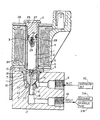
- the valve has a movable armature 1 cooperative with a fixed armature 2 to rise and compress a return spring 3 when a solonoid coil 4 is energized.
- an integral conical closure needle portion 5 which normally obturates a limited pilot passage 6 in a push-fitted insert 7 located centrally in a flap 8, opens the passage 6 to fluid flow.
- the flap is a delayed movement flap, ie it only moves a finite time after being commanded to move.
- the valve has an inlet port 9 which always communicates, via a side passage 10 (between the flap 8 and a tubular extension 1 of a non-magnetic axial guide 12 for the soft steel movable armature 1), with a space 13 above the valve flap 8.
- a side passage 10 between the flap 8 and a tubular extension 1 of a non-magnetic axial guide 12 for the soft steel movable armature 1
- a space 13 above the valve flap 8.
- Whatever pressure exists at the inlet port then, is equalled in space 13 if passage 6 is closed by needle 5, and is almost equalled in space 13 if passage 6 has just been opened by raising of the obturating needle 5. This is because the resistance to fluid flow through passage 10 and across space 13 is designed to be much less than the resistance to fluid flow in pilot passage 6.
- Passage 10 may be multiple channels, or annular, or in any way adequate to maintain space 13 at about the same pressure as that at inlet 9.
- the flap is axially bored at 14, if desired not as constrictedly as passage 6 with which it is continuous, and this leads via an exit bore 15 to an outlet port 16, the second port of the valve.
- the inlet and outlet ports are formed, fitted or screwed, as desired, in an aluminium block 17 in which are fitted two items, namely the tubular extention 11 screwed in (preferably against one or more sealing O-rings 18) and also, by force fit, a valve seat body 19 for the conical end 20 of flap 8 to seat at 21.
- the valve seat body 19 includes exit bore 15 axially within it and also an abutment flange 22 against which a weak compression spring 23 tends to raise flap 8 from its seat 21, but it can only do this when both of the following occur, namely (1) when the pressure at the outlet port 16 at least almost equals that at space 13 (ie the two ports have nearly equal pressure), and (2) the movable armature and its needle 5 have been raised. Otherwise spring 3 and/or pressure at space 13 keep the flap on its seat.
- the exit bore 15 has preferably a cross-section matching that of the inlet port 9, to assist avoidance of flow energy losses on reverse flow, outlet-to-inlet.
- spring 3 must be strong enough to overcome spring 8 on non-energization or after switch-off of the coil, whatever the relative pressures. Yet spring 3 must be overcome by the mobile armature when electromagnetically raised.
- the armature guide 12 or any other fixed member of the valve or the valve body 17, must have one or more abutments 24, perhaps annular, to limit the rise, of the flap under all conditions, relative to the needle 5 when raised, in order to prevent the raised needle obturating the constricted passage 6.
- Spring 23 or excess pressure at exit 16 can then never push the flap upwards onto the raised needle.
- the abutment(s) 24 must peform this limiting action without obstructing fluid flow across space 13.
- the form or disposition of the abutments and/or the top of the valve flap must be such as to allow such fluid flow.
- Presently preferred are radial grooves (not illustrated) in the top surface of the flap, but many shapings will suggest themselves. Enough area of the flap top must be exposed to the fluid pressure, to give sufficient downward force to overcome spring 23 and seat the flap until the port pressures are nearly enough equalized.
- the fixed armature 2 may have a flanged top 25 to clamp an annular soft steel magnetic circuit member 26 against non-magnetic coil former 27 when screwed into valve guide 12 and also compressing a gasket 28. Both armatures may have central blind bores 29 to accommodate return spring 3. Other mechanical details are routine and variable.
- valve is most useful intermediate a vehicle hydraulic oil suspension unit 30 (such as on some Citroen cars and other vehicles) connected to its "input" port and a pump 31 at its outlet port 16. There are several conditions and requirements met by this valve.
- the relative flows in moderately restricted passage 10 and space 13 relative to constricted passage 6 will be critical, and selected in accordance with accepted pressure differences.
- French Patent Application 85 03795 describes an all or nothing two-port valve having a piloted valve with a flap tending to be held closing a port against a weak spring, by a stronger spring between divided armature members.
- the reference flap is not held down by fluid pressure because the flap is disclosed as being in hydrualic equilibrium.
- the valve is intended to be connected oppositely to that of the present invention, because the reference flap opens a fluid way between the utilization position (eg a suspension unit) and the interior of the housing.
- the reference valve is described and illustrated with relatively flat (not conical or needle-pointed) moving closure members which could not maintain pressure differences for long periods.
Landscapes
- Engineering & Computer Science (AREA)
- Mechanical Engineering (AREA)
- General Engineering & Computer Science (AREA)
- Magnetically Actuated Valves (AREA)
- Vehicle Body Suspensions (AREA)
Applications Claiming Priority (2)
| Application Number | Priority Date | Filing Date | Title |
|---|---|---|---|
| GB868623860A GB8623860D0 (en) | 1986-10-03 | 1986-10-03 | Two-way fluid valve |
| GB8623860 | 1986-10-03 |
Publications (3)
| Publication Number | Publication Date |
|---|---|
| EP0263346A2 true EP0263346A2 (de) | 1988-04-13 |
| EP0263346A3 EP0263346A3 (en) | 1990-04-25 |
| EP0263346B1 EP0263346B1 (de) | 1992-05-13 |
Family
ID=10605263
Family Applications (1)
| Application Number | Title | Priority Date | Filing Date |
|---|---|---|---|
| EP19870113799 Expired EP0263346B1 (de) | 1986-10-03 | 1987-09-22 | Zweiwegeventil |
Country Status (3)
| Country | Link |
|---|---|
| EP (1) | EP0263346B1 (de) |
| DE (1) | DE3779037D1 (de) |
| GB (1) | GB8623860D0 (de) |
Cited By (7)
| Publication number | Priority date | Publication date | Assignee | Title |
|---|---|---|---|---|
| WO1991010077A1 (en) * | 1989-12-21 | 1991-07-11 | Monroe Europe (Uk) Limited | Adaptive shock absorbers and damping valves therefor |
| EP0400301A3 (de) * | 1989-05-30 | 1992-05-06 | WABCO Vermögensverwaltungs-GmbH | Niveauregeleinrichtung für Fahrzeuge |
| EP0490262A3 (en) * | 1990-12-08 | 1992-11-19 | Fichtel & Sachs Ag | Check valve |
| FR2738049A1 (fr) * | 1995-08-23 | 1997-02-28 | Bosch Gmbh Robert | Electrovanne, notamment pour une installation de freinage hydraulique a regulation de patinage de vehicule automobile |
| EP1865114A1 (de) * | 2006-06-09 | 2007-12-12 | Volvo Construction Equipment Holding Sweden AB | Arbeitszylinderstruktur zur Achsblockierung für schwere Baugeräte |
| WO2015078563A1 (en) * | 2013-11-26 | 2015-06-04 | Nissan Motor Co., Ltd. | Extraction valve |
| CN111306344A (zh) * | 2019-12-06 | 2020-06-19 | 珠海格力电器股份有限公司 | 电磁阀和空气悬架充放气装置 |
Family Cites Families (1)
| Publication number | Priority date | Publication date | Assignee | Title |
|---|---|---|---|---|
| FR2578617B1 (fr) * | 1985-03-11 | 1987-11-13 | Peugeot | Electro-vanne a ouverture differee |
-
1986
- 1986-10-03 GB GB868623860A patent/GB8623860D0/en active Pending
-
1987
- 1987-09-22 EP EP19870113799 patent/EP0263346B1/de not_active Expired
- 1987-09-22 DE DE8787113799T patent/DE3779037D1/de not_active Expired - Lifetime
Cited By (15)
| Publication number | Priority date | Publication date | Assignee | Title |
|---|---|---|---|---|
| EP0400301A3 (de) * | 1989-05-30 | 1992-05-06 | WABCO Vermögensverwaltungs-GmbH | Niveauregeleinrichtung für Fahrzeuge |
| WO1991010077A1 (en) * | 1989-12-21 | 1991-07-11 | Monroe Europe (Uk) Limited | Adaptive shock absorbers and damping valves therefor |
| EP0490262A3 (en) * | 1990-12-08 | 1992-11-19 | Fichtel & Sachs Ag | Check valve |
| US5449055A (en) * | 1990-12-08 | 1995-09-12 | Fichtel & Sachs Ag | Stop valve device |
| FR2738049A1 (fr) * | 1995-08-23 | 1997-02-28 | Bosch Gmbh Robert | Electrovanne, notamment pour une installation de freinage hydraulique a regulation de patinage de vehicule automobile |
| US5810330A (en) * | 1995-08-23 | 1998-09-22 | Robert Bosch Gmbh | Magnetic valve for a traction-controlled hydraulic brake system for motor vehicles |
| EP1865114A1 (de) * | 2006-06-09 | 2007-12-12 | Volvo Construction Equipment Holding Sweden AB | Arbeitszylinderstruktur zur Achsblockierung für schwere Baugeräte |
| US7748309B2 (en) | 2006-06-09 | 2010-07-06 | Volvo Construction Equipment Holding Sweden Ab | Axle locking cylinder structure for heavy construction equipment |
| CN101086166B (zh) * | 2006-06-09 | 2011-08-31 | 沃尔沃建造设备控股(瑞典)有限公司 | 用于重型建设设备的车轴锁定汽缸结构 |
| WO2015078563A1 (en) * | 2013-11-26 | 2015-06-04 | Nissan Motor Co., Ltd. | Extraction valve |
| JP2016539291A (ja) * | 2013-11-26 | 2016-12-15 | 日産自動車株式会社 | 抽気弁 |
| CN106415088A (zh) * | 2013-11-26 | 2017-02-15 | 日产自动车株式会社 | 抽气阀 |
| US9879787B2 (en) | 2013-11-26 | 2018-01-30 | Nissan Motor Co., Ltd. | Extraction valve |
| CN106415088B (zh) * | 2013-11-26 | 2018-11-06 | 日产自动车株式会社 | 抽气阀 |
| CN111306344A (zh) * | 2019-12-06 | 2020-06-19 | 珠海格力电器股份有限公司 | 电磁阀和空气悬架充放气装置 |
Also Published As
| Publication number | Publication date |
|---|---|
| GB8623860D0 (en) | 1986-11-05 |
| DE3779037D1 (de) | 1992-06-17 |
| EP0263346B1 (de) | 1992-05-13 |
| EP0263346A3 (en) | 1990-04-25 |
Similar Documents
| Publication | Publication Date | Title |
|---|---|---|
| US5375683A (en) | Controllable vibration damper for motor vehicles | |
| US5503184A (en) | Pressure control valve | |
| US6499577B2 (en) | Valve apparatus for controlling hydraulic pressure for a clutch or a brake and method for controlling hydraulic pressure | |
| US6264015B1 (en) | Continuously variable single-tube shock absorber with bidirectional control valve | |
| US6021997A (en) | Proportional power control valve | |
| EP0344544A1 (de) | Antiblockier-Mechanismus | |
| KR20030044814A (ko) | 감쇠력 조정식 유압 완충기 | |
| EP0666803B1 (de) | Fahrzeugaufhängungssystem für verstellbares bewegungsniveau | |
| JP2000503613A (ja) | 特に自動車の液圧的なブレーキ装置のための電磁操作される弁 | |
| US6702075B2 (en) | Controllable shock absorber | |
| EP0263346B1 (de) | Zweiwegeventil | |
| JPS61132787A (ja) | 可変吐出量ポンプの制御弁装置 | |
| US9599247B2 (en) | Electromagnetic valve for controlling the flow of a pressure medium | |
| JP7657563B2 (ja) | 2段電磁弁 | |
| CA2793038C (en) | Pressure control to supply fuel and fuel supply system with a control unit comprising this pressure control | |
| US4508012A (en) | High pressure hydraulic systems | |
| JP2002509839A (ja) | 電磁バルブ | |
| US20040130421A1 (en) | Proportional pressure control valve for controlling the pressure level in a hydraulic circuit | |
| US5584224A (en) | Hydraulic systems | |
| US7798173B2 (en) | Electrically controllable valve | |
| GB2186349A (en) | Proportional solenoid valve | |
| US6508521B2 (en) | Anti-locking brake system | |
| US20040155215A1 (en) | Electromagnetic double switching valve | |
| US20190162319A1 (en) | Device for flow force compensation | |
| CZ279519B6 (cs) | Vyrovnavač pro soustavu motorového vozidla |
Legal Events
| Date | Code | Title | Description |
|---|---|---|---|
| PUAI | Public reference made under article 153(3) epc to a published international application that has entered the european phase |
Free format text: ORIGINAL CODE: 0009012 |
|
| AK | Designated contracting states |
Kind code of ref document: A2 Designated state(s): DE FR GB IT |
|
| PUAL | Search report despatched |
Free format text: ORIGINAL CODE: 0009013 |
|
| AK | Designated contracting states |
Kind code of ref document: A3 Designated state(s): DE FR GB IT |
|
| RHK1 | Main classification (correction) |
Ipc: B60G 17/00 |
|
| 17P | Request for examination filed |
Effective date: 19900514 |
|
| 17Q | First examination report despatched |
Effective date: 19910808 |
|
| GRAA | (expected) grant |
Free format text: ORIGINAL CODE: 0009210 |
|
| ITF | It: translation for a ep patent filed | ||
| AK | Designated contracting states |
Kind code of ref document: B1 Designated state(s): DE FR GB IT |
|
| ET | Fr: translation filed | ||
| REF | Corresponds to: |
Ref document number: 3779037 Country of ref document: DE Date of ref document: 19920617 |
|
| PLBE | No opposition filed within time limit |
Free format text: ORIGINAL CODE: 0009261 |
|
| STAA | Information on the status of an ep patent application or granted ep patent |
Free format text: STATUS: NO OPPOSITION FILED WITHIN TIME LIMIT |
|
| 26N | No opposition filed | ||
| REG | Reference to a national code |
Ref country code: GB Ref legal event code: IF02 |
|
| PGFP | Annual fee paid to national office [announced via postgrant information from national office to epo] |
Ref country code: GB Payment date: 20030807 Year of fee payment: 17 |
|
| PGFP | Annual fee paid to national office [announced via postgrant information from national office to epo] |
Ref country code: DE Payment date: 20030930 Year of fee payment: 17 |
|
| PG25 | Lapsed in a contracting state [announced via postgrant information from national office to epo] |
Ref country code: GB Free format text: LAPSE BECAUSE OF NON-PAYMENT OF DUE FEES Effective date: 20040922 |
|
| PG25 | Lapsed in a contracting state [announced via postgrant information from national office to epo] |
Ref country code: DE Free format text: LAPSE BECAUSE OF NON-PAYMENT OF DUE FEES Effective date: 20050401 |
|
| GBPC | Gb: european patent ceased through non-payment of renewal fee |
Effective date: 20040922 |
|
| PG25 | Lapsed in a contracting state [announced via postgrant information from national office to epo] |
Ref country code: IT Free format text: LAPSE BECAUSE OF NON-PAYMENT OF DUE FEES;WARNING: LAPSES OF ITALIAN PATENTS WITH EFFECTIVE DATE BEFORE 2007 MAY HAVE OCCURRED AT ANY TIME BEFORE 2007. THE CORRECT EFFECTIVE DATE MAY BE DIFFERENT FROM THE ONE RECORDED. Effective date: 20050922 |
|
| PGFP | Annual fee paid to national office [announced via postgrant information from national office to epo] |
Ref country code: FR Payment date: 20060906 Year of fee payment: 20 |