EP0263419A2 - Vergaser - Google Patents
Vergaser Download PDFInfo
- Publication number
- EP0263419A2 EP0263419A2 EP87114209A EP87114209A EP0263419A2 EP 0263419 A2 EP0263419 A2 EP 0263419A2 EP 87114209 A EP87114209 A EP 87114209A EP 87114209 A EP87114209 A EP 87114209A EP 0263419 A2 EP0263419 A2 EP 0263419A2
- Authority
- EP
- European Patent Office
- Prior art keywords
- fuel
- liquid level
- passageway
- flow rate
- air
- Prior art date
- Legal status (The legal status is an assumption and is not a legal conclusion. Google has not performed a legal analysis and makes no representation as to the accuracy of the status listed.)
- Withdrawn
Links
Images

Classifications
-
- F—MECHANICAL ENGINEERING; LIGHTING; HEATING; WEAPONS; BLASTING
- F02—COMBUSTION ENGINES; HOT-GAS OR COMBUSTION-PRODUCT ENGINE PLANTS
- F02M—SUPPLYING COMBUSTION ENGINES IN GENERAL WITH COMBUSTIBLE MIXTURES OR CONSTITUENTS THEREOF
- F02M5/00—Float-controlled apparatus for maintaining a constant fuel level
- F02M5/10—Float-controlled apparatus for maintaining a constant fuel level having means for preventing vapour lock, e.g. insulated float chambers or forced fuel circulation through float chamber with engine stopped
-
- F—MECHANICAL ENGINEERING; LIGHTING; HEATING; WEAPONS; BLASTING
- F02—COMBUSTION ENGINES; HOT-GAS OR COMBUSTION-PRODUCT ENGINE PLANTS
- F02M—SUPPLYING COMBUSTION ENGINES IN GENERAL WITH COMBUSTIBLE MIXTURES OR CONSTITUENTS THEREOF
- F02M17/00—Carburettors having pertinent characteristics not provided for in, or of interest apart from, the apparatus of preceding main groups F02M1/00 - F02M15/00
- F02M17/02—Floatless carburettors
-
- F—MECHANICAL ENGINEERING; LIGHTING; HEATING; WEAPONS; BLASTING
- F02—COMBUSTION ENGINES; HOT-GAS OR COMBUSTION-PRODUCT ENGINE PLANTS
- F02M—SUPPLYING COMBUSTION ENGINES IN GENERAL WITH COMBUSTIBLE MIXTURES OR CONSTITUENTS THEREOF
- F02M7/00—Carburettors with means for influencing, e.g. enriching or keeping constant, fuel/air ratio of charge under varying conditions
- F02M7/12—Other installations, with moving parts, for influencing fuel/air ratio, e.g. having valves
Definitions
- the present invention relates to a carburetor and more particularly a floatless carburetor for internal combustion engines.
- the air bubbles flowing through an air vent 21 enter an intake passageway to induce the generation of a rich mixture in an extreme case and consequently the mixture introduced into the cylinder of an engine may have an air-fuel ratio beyond the range of combustibility.
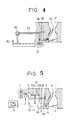
- a problem of the air bubbles may be brought about not only in the float type carburetor, but also in the so-called floatless carburetor shown in Fig. 4 as an example.
- the air bubbles are produced on the downstream side of a fuel flow rate control device 37 opening and closing properly a fuel passageway 35, in accordance with the fluctuation of a fuel liquid level in a passageway 38 for fuel liquid level detection, supplying the fuel from a fuel tank 30 to a main nozzle 33 within an intake passageway 31 through a pump 36 and, as the result, the fuel spouts from the passageway 38 for fuel liquid level detection to generate the rich mixture.
- the object of the present invention in view of such circumstances, is to provide a floatless carburetor which prevents surely the generation of the air bubbles in the fuel to be supplied and which can properly feed the fuel.
- an air-liquid separating chamber is provided on the downstream side of a fuel flow rate control device and communicates with the atmosphere through a passageway with a diameter smaller than that of a passageway for fuel liquid level detection located on a further downstream side thereof.
- the pressure in the separating chamber rises, thereby causing the liquid level in the passageway for fuel liquid level detection to be elevated and, as a result, the fuel flow rate control device will cease to supply the fuel in accordance with a signal issued from a liquid level sensor disposed along the passageway for fuel liquid level detection. Accordingly, the spouting of the fuel from the passageway for fuel liquid level detection is prevented and therefore the generation of the rich mixture is assuredly blocked.
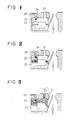
- reference numeral 1 designates a suction bore, 2 a throttle valve placed in the suction bore 1, 3 a nozzle disposed in a venturi portion within the suction bore 1, 4 a metering jet 5, a fuel passageway for supplying the fuel from a fuel feed system comprising a fuel pump 6 to the nozzle 3, 7 a fuel flow rate control device composed of a solenoid valve arranged midway in the fuel passageway 5 between the metering jet 4 and the fuel pump 6, 8 a passageway for fuel liquid level detection connected to a portion between the fuel flow rate control device 7 in the fuel passageway 5 and the metering jet 4 at the lower end and communicating with the atmosphere at the upper end, 9 a liquid level sensor device disposed in the passageway 8 for fuel liquid level detection, 10 an air-liquid separating chamber divided into chambers 10a and 10b by a partition wall 11 disposed in the middle of
- the liquid level sensor device 9 comprises, for example, a light emitting element 9a and a light receiving element 9b and a circuit for detection, not shown, connected to these elements, and is adapted to be actuated so that when the fuel liquid level in the passageway 8 for fuel liquid level detection is lower than the position of a preset height, the output of the circuit for detection according to the output of the light receiving element 9b is reduced, while on the other hand, when the fuel liquid level is above the preset height, the output is increased (refer to Fig. 6). Further, the liquid level sensor device 9 of the type, connected to such a control circuit 13 as shown in Fig.
- the fuel flow rate control device 7 opens the fuel passageway 5, and the increase of the fuel flow rate causes the liquid level to be raised, while on the other hand, when the liquid level is higher than the preset position of height, that is, when the output of the liquid level sensor device 9 is higher than the reference voltage E0, the output of the operational amplifier COP becomes "L” to cut off the conduction of the transistor Tr, thereby the fuel flow rate control device 7 closes the fuel passageway 5, and the decrease of the fuel flow rate causes the liquid level to be lowered.
- the carburetor according to the present invention is constructed as mentioned above, with respect to the basic operation thereof, when the liquid level in the passageway 8 for fuel liquid level detection is positioned below the preset height, the fuel flow rate control device 7 is operated by the control circuit 13 (Fig. 7) to cause the liquid level to be raised, whereas, when the liquid level is above the preset height, it is lowered. Such operations are repeated alternately and thereby the liquid level is maintained at the preset height, that is, a reference liquid level is formed. Also, in such a case, both the air-liquid separating chamber 10 and the passageway 8 for fuel liquid level detection communicate with the atmosphere, so that theoretically their liquid levels are the same in height.
- the air bubbles are generated in the fuel on the downstream of the fuel flow rate control device 7, at high temperatures in particular, and if the amount of the air bubbles is considerably small, the fuel is first introduced from the chamber 10a side into the air-liquid separating chamber 10. Therefore, the flow of the air bubbles into the chamber 10b is almost completely blocked by the partition wall 11, so that the chamber 10b is filled with pure fuel which does not include any of the air bubbles. Further, as a result, the reference liquid level is formed by virtue of the chamber 10b and the passageway 8 for fuel liquid level detection, and a fuel supply to the nozzle 3 through the metering jet 4 can properly be controlled.
- the air bubbles flow into the chamber 10b beyond the partition wall 11 and thereby the air-liquid separating chamber 10 is filled with the air bubbles.
- the liquid level in the passageway 8 for fuel liquid level detection will be raised.
- the output of the liquid level sensor device 9 is increased and, in accordance with the signal of the output, the fuel supply to the air-liquid separating chamber 10 is stopped immediately by the fuel flow rate control device 7 through the control circuit 13, so that the fuel will not be spouted from the passageway 8 for fuel liquid level detection and the passageway 12.
- the diameter of the passageway 12 is set to be at least smaller than that of the passageway 8 for fuel liquid level detection, even when the air-liquid separating chamber 10 is filled with the air bubbles, not only the amount of the air bubbles flowing through the passageway 12 is minimized, but also the atmosphere is introduced into the air-liquid separating chamber 10 to compensate a pressure rising function caused by the air bubbles in the air-liquid separating chamber 10 and, as a result, a proper formation of the reference liquid level in the passageway 8 for fuel liquid level detection can be realized.
- the fuel and air components of the air bubbles once generated are progressively absorbed into the fuel in the air-liquid separating chamber 10 or into the atmosphere through the passageway 12 and, after this, the pressure within the air-liquid separating chamber 10 returns to a state of the atmospheric pressure.
- a proper fuel supply can always be performed without bringing about the rich mixture attributable to the air bubbles generated in the fuel to be supplied.
- the carburetor according to the present invention has an excellent advantage in practical use that barriers to the fuel supply which are caused by the air bubbles generated in the fuel at high temperatures in particular are positively eliminated and a proper fuel supply can always be carried out.
Landscapes
- Engineering & Computer Science (AREA)
- Chemical & Material Sciences (AREA)
- Combustion & Propulsion (AREA)
- Mechanical Engineering (AREA)
- General Engineering & Computer Science (AREA)
- Feeding And Controlling Fuel (AREA)
- Jet Pumps And Other Pumps (AREA)
- Control Of The Air-Fuel Ratio Of Carburetors (AREA)
- Measuring Volume Flow (AREA)
- Degasification And Air Bubble Elimination (AREA)
Applications Claiming Priority (2)
| Application Number | Priority Date | Filing Date | Title |
|---|---|---|---|
| JP1986149231U JPS6354853U (de) | 1986-09-29 | 1986-09-29 | |
| JP149231/86U | 1986-09-29 |
Publications (2)
| Publication Number | Publication Date |
|---|---|
| EP0263419A2 true EP0263419A2 (de) | 1988-04-13 |
| EP0263419A3 EP0263419A3 (de) | 1988-08-03 |
Family
ID=15470738
Family Applications (1)
| Application Number | Title | Priority Date | Filing Date |
|---|---|---|---|
| EP87114209A Withdrawn EP0263419A3 (de) | 1986-09-29 | 1987-09-29 | Vergaser |
Country Status (3)
| Country | Link |
|---|---|
| EP (1) | EP0263419A3 (de) |
| JP (1) | JPS6354853U (de) |
| KR (1) | KR880004218A (de) |
Family Cites Families (4)
| Publication number | Priority date | Publication date | Assignee | Title |
|---|---|---|---|---|
| JPS5458141A (en) * | 1977-10-19 | 1979-05-10 | Toyota Motor Corp | Carbureter float chamber equipment |
| DE2910605A1 (de) * | 1979-03-17 | 1980-09-25 | Pierburg Gmbh & Co Kg | Vergaser fuer verbrennungsmotoren |
| US4325894A (en) * | 1979-07-11 | 1982-04-20 | Honda Giken Kogyo Kabushiki Kaisha | Apparatus for control of liquid level in carburetor |
| DE3334376A1 (de) * | 1983-09-23 | 1985-04-11 | Volkswagenwerk Ag, 3180 Wolfsburg | Vergaser fuer eine brennkraftmaschine |
-
1986
- 1986-09-29 JP JP1986149231U patent/JPS6354853U/ja active Pending
-
1987
- 1987-09-28 KR KR870010780A patent/KR880004218A/ko not_active Withdrawn
- 1987-09-29 EP EP87114209A patent/EP0263419A3/de not_active Withdrawn
Also Published As
| Publication number | Publication date |
|---|---|
| EP0263419A3 (de) | 1988-08-03 |
| JPS6354853U (de) | 1988-04-13 |
| KR880004218A (ko) | 1988-06-02 |
Similar Documents
| Publication | Publication Date | Title |
|---|---|---|
| US4271093A (en) | Carburetor | |
| US4369749A (en) | Variable venturi carburetor | |
| EP0021295A1 (de) | Hilfszufuhrvorrichtung für den Brennstoff für Brennkraftmaschinen | |
| EP0247276A2 (de) | Vergasersystem für eine Brennkraftmaschine | |
| CA1091999A (en) | Primer for an internal combustion engine | |
| US4139580A (en) | Self-lift carburetor | |
| EP0263419A2 (de) | Vergaser | |
| US3872851A (en) | Fuel supply device for an internal combustion engine | |
| CN100404844C (zh) | 用于内燃机中的燃油供给系统的蒸汽去除装置 | |
| CA1154337A (en) | Internally vented float bowl primer arrangement | |
| US4150648A (en) | Exhaust gas recirculation engine for high altitude use | |
| US4765932A (en) | Fuel supply device for carburetors | |
| US4518540A (en) | Multi-fuel carburetor | |
| US4353345A (en) | Carburetor | |
| JP4030939B2 (ja) | 燃料送出システムおよび方法 | |
| US1383044A (en) | Carbureter for internal-combustion engines | |
| US20230021438A1 (en) | Fuel and air charge forming device | |
| JPH0524351B2 (de) | ||
| US4567871A (en) | Fuel distribution and metering | |
| US2875741A (en) | Deceleration control system | |
| EP1342906B1 (de) | Vergaser mit Leerkraftstoffversorgungsanlage | |
| US3171467A (en) | Carburetor control | |
| JP2505486B2 (ja) | 燃料タンク装置 | |
| JPH0270965A (ja) | 気化器 | |
| JP2791432B2 (ja) | エンジンの燃料供給装置 |
Legal Events
| Date | Code | Title | Description |
|---|---|---|---|
| PUAI | Public reference made under article 153(3) epc to a published international application that has entered the european phase |
Free format text: ORIGINAL CODE: 0009012 |
|
| AK | Designated contracting states |
Kind code of ref document: A2 Designated state(s): DE FR GB IT |
|
| PUAL | Search report despatched |
Free format text: ORIGINAL CODE: 0009013 |
|
| AK | Designated contracting states |
Kind code of ref document: A3 Designated state(s): DE FR GB IT |
|
| 17P | Request for examination filed |
Effective date: 19880816 |
|
| 17Q | First examination report despatched |
Effective date: 19890329 |
|
| STAA | Information on the status of an ep patent application or granted ep patent |
Free format text: STATUS: THE APPLICATION IS DEEMED TO BE WITHDRAWN |
|
| 18D | Application deemed to be withdrawn |
Effective date: 19890808 |
|
| RIN1 | Information on inventor provided before grant (corrected) |
Inventor name: MURAJI, TETSUO Inventor name: SEKIYA, MITSURU |