EP0263471A2 - Distributeur d'engrais à disque centrifuge - Google Patents
Distributeur d'engrais à disque centrifuge Download PDFInfo
- Publication number
- EP0263471A2 EP0263471A2 EP87114524A EP87114524A EP0263471A2 EP 0263471 A2 EP0263471 A2 EP 0263471A2 EP 87114524 A EP87114524 A EP 87114524A EP 87114524 A EP87114524 A EP 87114524A EP 0263471 A2 EP0263471 A2 EP 0263471A2
- Authority
- EP
- European Patent Office
- Prior art keywords
- centrifugal
- fertilizer
- row
- spreading
- throwing
- Prior art date
- Legal status (The legal status is an assumption and is not a legal conclusion. Google has not performed a legal analysis and makes no representation as to the accuracy of the status listed.)
- Granted
Links
Images


Classifications
-
- A—HUMAN NECESSITIES
- A01—AGRICULTURE; FORESTRY; ANIMAL HUSBANDRY; HUNTING; TRAPPING; FISHING
- A01C—PLANTING; SOWING; FERTILISING
- A01C17/00—Fertilisers or seeders with centrifugal wheels
- A01C17/006—Regulating or dosing devices
- A01C17/008—Devices controlling the quantity or the distribution pattern
-
- A—HUMAN NECESSITIES
- A01—AGRICULTURE; FORESTRY; ANIMAL HUSBANDRY; HUNTING; TRAPPING; FISHING
- A01C—PLANTING; SOWING; FERTILISING
- A01C15/00—Fertiliser distributors
- A01C15/005—Undercarriages, tanks, hoppers, stirrers specially adapted for seeders or fertiliser distributors
- A01C15/008—Aprons; Deflecting plates; Band-spreading attachments
Definitions
- the invention relates to a centrifugal fertilizer spreader with at least one centrifugal disc arranged below a storage container for the fertilizer to be spread out and provided with throwing elements for throwing off the fertilizer, and with a row spreading device for fertilizing row crops which contain a collecting container which collects the spun off fertilizer and has guide devices which divide up two or more tubular lines includes.
- centrifugal fertilizer spreader is already known from DE-GM 71 16 432.
- This centrifugal fertilizer broadcaster equipped with a row spreading device, is equipped with a collecting container surrounding the spreading members designed as centrifugal disks.
- This collecting container is arranged in the area of the centrifugal disks in such a way that it collects the fertilizer particles thrown off by the centrifugal disks.
- the fertilizer particles thrown off by a scattering device are distributed to two outlet openings and slid to the ground, so that a four-row row spreading device can be supplied with fertilizer using such a two-disc centrifugal fertilizer spreader.
- a guide or dividing device pointing in the direction of the respective scattering element is arranged between two outlet openings assigned to a scattering element and can be locked in an adjustable position so that the fertilizer particles thrown off by a scattering element are evenly distributed over two outlet openings.
- This centrifugal fertilizer spreader equipped with a row spreading device for fertilizing row crops has the disadvantage that the fertilizer particles are thrown off with the same discharge speed as with normal spreading, i.e. when using the centrifugal fertilizer spreader without row spreading device, and consequently thrown into the collecting container at high speed.
- the fertilizer particles thrown into the collecting container therefore hit the walls of the collecting container with great energy and bounce back from them in an uncontrolled manner. This makes it very difficult and in some cases impossible to evenly distribute the fertilizer flow thrown off by the scattering elements onto the individual outlet openings.
- Characterized in that the fertilizer particles are thrown into the collecting container at high speed and hit the walls of the collecting container with great energy this leads to grain breakage, dust formation and damage to parts of the collecting container. As a result of the breakage of the grains and the resulting dust-like parts of the fertilizer, it is impossible to allocate them evenly to the individual outlet openings.
- centrifugal fertilizer spreader which are designed and designed for spreading the fertilizer over working widths of 18 to 24 m and more, for use with row spreading devices in such a way that the without problems in connection with row spreading devices for row fertilizer spreading , for example for fertilizing corn.
- the discharge speed at the discharge edge of the throwing elements during row spreading is reduced to approximately 8 to 10 m per second.
- the lower discharge speeds are used for a six-row and the higher for an eight-row row spreader. These discharge speeds are chosen such that they are still large enough to distribute the fertilizer particles evenly over the individual sub-containers of the collecting container.
- the discharge speeds according to the invention ensure that the fertilizer particles thrown off the centrifugal disks with the help of the throwing elements practically do not break up or only to an insignificant extent when they hit the components of the row spreading device, or that these components are damaged.
- this low ejection speed at the ejection edge of the throwing elements is achieved by exchanging the throwing elements, the throwing elements being arranged on the centrifugal disks in an easily detachable manner. This creates another possibility for reducing the discharge speed.
- this lower ejection speed at the ejection edge of the throwing elements can be achieved by changing the drive speed of the centrifugal disks, the reduction in the number of drives of the centrifugal disks being achievable, for example, with a Welelsel transmission or an adjustable transmission.
- the reduction in the drive speed of the centrifugal discs represents a further possibility for reducing the discharge speed for the fertilizer particles, so that the fertilizer particles hit the walls of the collecting container when fertilizing in rows at a slower speed according to the invention.
- this low ejection speed at the ejection edge of the throwing elements can be achieved by changing the scattering elements and by reducing the operating speed.
- the throwing disks with their throwing elements can be replaced by differently designed throwing disks and / or differently designed scattering elements, and the throwing elements can be exchanged for differently designed throwing elements, or the throwing elements can be arranged differently on the throwing disks.
- the centrifugal fertilizer spreader designed for normal spreading for large working widths can be converted in a simple manner for the row fertilization of row crops with a row spreading device.
- a further possibility for reducing the discharge speed is achieved by reducing the drive speed of the centrifugal discs from the drive speed for normal fertilization to a lower drive speed for row fertilization by reducing the engine speed or the PTO speed of the tractor, especially in connection with the change in the spreading elements is achieved.
- a peripheral speed at the discharge edges of about 20 to 30 m per second is adjustable, while the peripheral speed at the discharge edges of the discharge elements for row fertilization with six to eight rows can be reduced to about 8 to 10 m per second.
- the spreading fans generated by the two centrifugal disks arranged next to one another overlap at least approximately during normal fertilization, and that these two spreading fans also overlap at least approximately in the arrangement of the row spreading device. This results in a particularly good, uniform distribution of the fertilizer particles thrown off the centrifugal disks into the individual sub-containers of the collecting container, to which the tubular lines are connected.
- each line is assigned a funnel-shaped partial area of the receiving container, the funnel-shaped partial areas being arranged next to one another.
- the distance between the lid of the collecting container and the intermediate walls of the funnel-shaped partial regions increases from the center of the collecting container to the side and outside, the upper edges of the intermediate walls being arranged lower in the outer region of the collecting container than in the central region of the collecting container. This ensures that the fertilizer particle thrown off by the centrifugal disks is evenly distributed over the funnel-shaped partial areas assigned to each line.
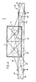
- the centrifugal fertilizer spreader according to FIG. 1 has the frame 1, the storage container 2 and the centrifugal disks 3 with the throwing elements 4 arranged under the storage container 2.
- the three-point coupling elements 5 are arranged so that the centrifugal fertilizer spreader can be attached to the three-point linkage of a tractor.
- the centrifugal disks 3 are detachably arranged on each transmission output shaft 6.
- the transmission output shafts 6 end at a distance below the storage container 2, so that the centrifugal disks 3 can be removed from the shafts 6 or be fitted onto the shafts 6 without dismantling the transmission 7 or the storage container 2.
- centrifugal disks 3 arranged on the transmission output shafts 6, the fertilizer particles are thrown off over a large working area, so that working widths of up to 24 m and more can be achieved.
- the centrifugal discs 3 must have a very high peripheral speed, so that the fertilizer particles are thrown out uniformly over the entire spreading area.
- These high peripheral speeds of the centrifugal discs 3 can be achieved by centrifugal discs with a large diameter D, the throwing elements 4 extending at least to the outer edge 8 or beyond it.
- the fertilizer particles fed to the centrifugal disks 3 from the storage container 2 are thrown off the throwing elements 4 at the respective discharge edge 9 at a high discharge speed.
- the peripheral speeds at the discharge edges 9 of the throwing elements 4 Circumferential speeds of approx. 20 to 30 m per second.
- the use of spreading discs 3 with different diameters D or the arrangement of throwing elements 4 of different lengths is achieved.
- the distance between the discharge edge 9 of the respective throwing elements 4 from the axis of rotation 10 of the centrifugal disc 3 is decisive for the discharge speed at which the fertilizer particles are thrown off by the centrifugal elements 4 of the centrifugal discs 3.
- the centrifugal fertilizer spreader is now to be used for the fertilization of row crops, for example for the fertilization of maize, then the normal spreading disks 3 are replaced by the row spreading disks 11 and the row spreading device 12 is fastened to the rear of the frame 1 by means of quick-release fasteners.
- the row spreading discs 11 have the throwing elements 13.
- the row spreading discs 11 can be the normal spreading discs 3 provided with other throwing elements 13.
- the throwing elements 13 are arranged on the row spreading disc 11 so that their throw-off edge 9 is at a substantially smaller distance from the axis of rotation 10 of the centrifugal disc 11 than the throw-off edge of the throw elements 4 of the normal spreading discs 3. Because the throw-off edge 9 of the throw elements 13 is less Has a distance from the axis of rotation 10 of the centrifugal disc, the fertilizer particles thrown off by the throwing elements are thrown off at a substantially lower discharge speed than in the case of the normal spreading disc 3 according to FIG Fig. 2. This low discharge speed of the fertilizer particles can also be achieved by spreading discs with a smaller diameter d, the respective discharge edge 9 of the throwing elements 13 coinciding approximately with the outer edge 8 of the row spreading discs 11.
- the row spreading device 12 is provided with a collecting container 14 which has six funnel-shaped partial boxes 15 firmly connected to one another in the middle. In extension of these partial boxes 15, a further partial box 15 'is arranged on the outside with the help of joints 16. Thus, these partial boxes 15 ⁇ can be pivoted into a working position laterally next to the partial boxes 15 and backwards through 180 ° into a transport position.
- the funnel-shaped partial boxes 15 and 15 ⁇ each have an opening 17 in their lower area, to which the tubular line 18 is connected.
- These lines 13 are pivotable and lockable on the sub-boxes 15 and 15 ⁇ so that the row spreading device 12 can be adapted to different row widths.
- the row spreading device 12 has a housing 19 which is easily detachably connected to the collecting container 14 and which is arranged around the centrifugal discs 11.
- the fertilizer particles are released from the throwing elements 13 the rotating centrifugal disks 11 are gripped and flung inside the housing 19 in the direction of the collecting container 14, with adjustable guide plates being arranged above the same or the sub-boxes 15, so as to ensure that each line 18 is the same Amount of fertilizer is supplied.
- the closed housing 19 ensures that no fertilizer particles are thrown past the row spreading device 12 or fall by, but in any case only reach the ground via the lines 18.
- the spreading compartments 11 produced by the two centrifugal disks 11 arranged next to one another overlap. These spreading fans are shown with dash-dotted lines in FIG. 6, the two lines 20 representing the spreading fan which is produced by the left spreading disc, and the lines 21 reflecting the spreading fan of the right spinner disc.
- the distance a between the upper edge 22 of the intermediate walls 23 and the lid 24 of the collecting container 14 from the center of the collecting container 14 increases laterally outwards. This ensures that the same amount of fertilizer is applied to the outer part boxes as the part boxes arranged in the middle of the machine.
- a reduction in the discharge speed of the fertilizer particles at the discharge edges 9 of the throwing elements can also be brought about by reducing the drive speed of the normal spreading discs 3, the reduction in the drive speed of the centrifugal discs 3 being achievable by means of a change gear 25 arranged on the centrifugal spreader.
Landscapes
- Life Sciences & Earth Sciences (AREA)
- Soil Sciences (AREA)
- Environmental Sciences (AREA)
- Fertilizing (AREA)
- Fertilizers (AREA)
Priority Applications (1)
| Application Number | Priority Date | Filing Date | Title |
|---|---|---|---|
| AT87114524T ATE84184T1 (de) | 1986-10-07 | 1987-10-05 | Schleuderduengerstreuer. |
Applications Claiming Priority (2)
| Application Number | Priority Date | Filing Date | Title |
|---|---|---|---|
| DE3634096 | 1986-10-07 | ||
| DE19863634096 DE3634096A1 (de) | 1986-10-07 | 1986-10-07 | Schleuderduengerstreuer |
Publications (3)
| Publication Number | Publication Date |
|---|---|
| EP0263471A2 true EP0263471A2 (fr) | 1988-04-13 |
| EP0263471A3 EP0263471A3 (en) | 1988-11-09 |
| EP0263471B1 EP0263471B1 (fr) | 1993-01-07 |
Family
ID=6311209
Family Applications (1)
| Application Number | Title | Priority Date | Filing Date |
|---|---|---|---|
| EP87114524A Expired - Lifetime EP0263471B1 (fr) | 1986-10-07 | 1987-10-05 | Distributeur d'engrais à disque centrifuge |
Country Status (3)
| Country | Link |
|---|---|
| EP (1) | EP0263471B1 (fr) |
| AT (1) | ATE84184T1 (fr) |
| DE (2) | DE3634096A1 (fr) |
Cited By (3)
| Publication number | Priority date | Publication date | Assignee | Title |
|---|---|---|---|---|
| FR2652231A1 (fr) * | 1989-09-23 | 1991-03-29 | Amazonen Werke Dreyer H | Distributeur d'engrais centrifuge pour traiter des cultures ou des plantations en lignes. |
| CN112970397A (zh) * | 2021-02-03 | 2021-06-18 | 代杰 | 一种用于农业种植的施肥设备 |
| CN114175900A (zh) * | 2021-07-03 | 2022-03-15 | 淮安市众鼎机械制造有限公司 | 一种自走式植保机用双盘撒肥机构 |
Families Citing this family (1)
| Publication number | Priority date | Publication date | Assignee | Title |
|---|---|---|---|---|
| DE3906782A1 (de) * | 1989-03-03 | 1990-09-13 | Amazonen Werke Dreyer H | Schleuderduengerstreuer |
Family Cites Families (7)
| Publication number | Priority date | Publication date | Assignee | Title |
|---|---|---|---|---|
| FR2144225A5 (fr) * | 1971-04-28 | 1973-02-09 | Amazonen Werke Dreyer H | |
| DE2407085A1 (de) * | 1974-02-14 | 1975-08-28 | Gerhard Rauch | Reihenstreuvorrichtung fuer schleuderduengerstreuer |
| DE2804253A1 (de) * | 1978-02-01 | 1979-08-02 | Amazonen Werke Dreyer H | Zentrifugalduengerstreuer mit zwei schleuderscheiben |
| NL190570C (nl) * | 1978-05-05 | 1994-05-02 | Lely Nv C Van Der | Inrichting voor het strooien van korrel- en/of poedervormig materiaal. |
| DE2908949C2 (de) * | 1979-03-07 | 1982-07-15 | Amazonen-Werke H. Dreyer Gmbh & Co Kg, 4507 Hasbergen | Schleuderdüngerstreuer |
| DE3337762C2 (de) * | 1983-10-18 | 1987-01-02 | Amazonen-Werke H. Dreyer Gmbh & Co Kg, 4507 Hasbergen | Schleuderstreuer |
| DE3527007A1 (de) * | 1985-07-27 | 1987-02-05 | Amazonen Werke Dreyer H | Reihenstreuvorrichtung fuer schleuderstreuer |
-
1986
- 1986-10-07 DE DE19863634096 patent/DE3634096A1/de not_active Withdrawn
-
1987
- 1987-10-05 AT AT87114524T patent/ATE84184T1/de not_active IP Right Cessation
- 1987-10-05 DE DE8787114524T patent/DE3783416D1/de not_active Expired - Fee Related
- 1987-10-05 EP EP87114524A patent/EP0263471B1/fr not_active Expired - Lifetime
Cited By (4)
| Publication number | Priority date | Publication date | Assignee | Title |
|---|---|---|---|---|
| FR2652231A1 (fr) * | 1989-09-23 | 1991-03-29 | Amazonen Werke Dreyer H | Distributeur d'engrais centrifuge pour traiter des cultures ou des plantations en lignes. |
| CN112970397A (zh) * | 2021-02-03 | 2021-06-18 | 代杰 | 一种用于农业种植的施肥设备 |
| CN112970397B (zh) * | 2021-02-03 | 2022-11-08 | 山东巴特农业科技有限公司 | 一种用于农业种植的施肥设备 |
| CN114175900A (zh) * | 2021-07-03 | 2022-03-15 | 淮安市众鼎机械制造有限公司 | 一种自走式植保机用双盘撒肥机构 |
Also Published As
| Publication number | Publication date |
|---|---|
| EP0263471A3 (en) | 1988-11-09 |
| DE3634096A1 (de) | 1988-04-14 |
| EP0263471B1 (fr) | 1993-01-07 |
| ATE84184T1 (de) | 1993-01-15 |
| DE3783416D1 (de) | 1993-02-18 |
Similar Documents
| Publication | Publication Date | Title |
|---|---|---|
| DE2908949C2 (de) | Schleuderdüngerstreuer | |
| EP0532055A2 (fr) | Méthode de distribution d'engrais par un épandeur centrifuge | |
| EP0192085B1 (fr) | Distributeur d'engrais à deux disques | |
| EP0327941B1 (fr) | Epandeur centrifuge | |
| EP0263471B1 (fr) | Distributeur d'engrais à disque centrifuge | |
| EP0292872B1 (fr) | Epandeur d'engrais centrifuge | |
| DE3337762A1 (de) | Verfahren zum ausbringen von duengemitteln | |
| EP0427936B1 (fr) | Epandeur d'engrais centrifuge | |
| EP0429864B2 (fr) | Epandeur d'engrais centrifuge | |
| EP0292650B1 (fr) | Epandeur d'engrais centrifuge | |
| DE3812087A1 (de) | Schleuderstreuer | |
| EP0211361B1 (fr) | Distributeur centrifuge | |
| EP0292874B1 (fr) | Distributeur à grand tonnage | |
| DE2407085A1 (de) | Reihenstreuvorrichtung fuer schleuderduengerstreuer | |
| DE3931835A1 (de) | Schleuderduengerstreuer | |
| EP0356770B1 (fr) | Distributeurs centrifuges d'engrais | |
| EP0385091A2 (fr) | Epandeur centrifuge | |
| EP0439718B1 (fr) | Epandeur centrifuge | |
| DE3917210A1 (de) | Schleuderduengerstreuer | |
| DE19735525A1 (de) | Verfahren zum Einsatz eines Zentrifugalstreuers | |
| DE19741653A1 (de) | Vorrichtung zum Aussteuern von körnigem Material | |
| EP0379103A1 (fr) | Epandeur centrifuge | |
| EP0386540B1 (fr) | Système de fabrication d'une série d'épandeurs de capacité croissante | |
| EP0175388B1 (fr) | Distributeur à disque centrifuge et procédé de fabrication d'un distributeur à disque centrifuge | |
| DE1557930C3 (de) | Landwirtschaftliche Maschine zum gleichmäßigen Verteilen von Saatgut und Düngemitteln |
Legal Events
| Date | Code | Title | Description |
|---|---|---|---|
| PUAI | Public reference made under article 153(3) epc to a published international application that has entered the european phase |
Free format text: ORIGINAL CODE: 0009012 |
|
| AK | Designated contracting states |
Kind code of ref document: A2 Designated state(s): AT BE CH DE ES FR GB IT LI LU NL SE |
|
| PUAL | Search report despatched |
Free format text: ORIGINAL CODE: 0009013 |
|
| AK | Designated contracting states |
Kind code of ref document: A3 Designated state(s): AT BE CH DE ES FR GB IT LI LU NL SE |
|
| 17P | Request for examination filed |
Effective date: 19890224 |
|
| 17Q | First examination report despatched |
Effective date: 19900906 |
|
| GRAA | (expected) grant |
Free format text: ORIGINAL CODE: 0009210 |
|
| AK | Designated contracting states |
Kind code of ref document: B1 Designated state(s): AT BE CH DE ES FR GB IT LI LU NL SE |
|
| PG25 | Lapsed in a contracting state [announced via postgrant information from national office to epo] |
Ref country code: IT Free format text: LAPSE BECAUSE OF FAILURE TO SUBMIT A TRANSLATION OF THE DESCRIPTION OR TO PAY THE FEE WITHIN THE PRE;WARNING: LAPSES OF ITALIAN PATENTS WITH EFFECTIVE DATE BEFORE 2007 MAY HAVE OCCURRED AT ANY TIME BEFORE 2007. THE CORRECT EFFECTIVE DATE MAY BE DIFFERENT FROM THE ONE RECORDED.SCRIBED TIME-LIMIT Effective date: 19930107 Ref country code: SE Effective date: 19930107 Ref country code: GB Effective date: 19930107 Ref country code: BE Effective date: 19930107 |
|
| REF | Corresponds to: |
Ref document number: 84184 Country of ref document: AT Date of ref document: 19930115 Kind code of ref document: T |
|
| ET | Fr: translation filed | ||
| REF | Corresponds to: |
Ref document number: 3783416 Country of ref document: DE Date of ref document: 19930218 |
|
| PG25 | Lapsed in a contracting state [announced via postgrant information from national office to epo] |
Ref country code: ES Free format text: LAPSE BECAUSE OF FAILURE TO SUBMIT A TRANSLATION OF THE DESCRIPTION OR TO PAY THE FEE WITHIN THE PRESCRIBED TIME-LIMIT Effective date: 19930418 |
|
| GBV | Gb: ep patent (uk) treated as always having been void in accordance with gb section 77(7)/1977 [no translation filed] |
Effective date: 19930107 |
|
| PG25 | Lapsed in a contracting state [announced via postgrant information from national office to epo] |
Ref country code: AT Effective date: 19931005 |
|
| PG25 | Lapsed in a contracting state [announced via postgrant information from national office to epo] |
Ref country code: LI Effective date: 19931031 Ref country code: LU Free format text: LAPSE BECAUSE OF NON-PAYMENT OF DUE FEES Effective date: 19931031 Ref country code: CH Effective date: 19931031 |
|
| PLBE | No opposition filed within time limit |
Free format text: ORIGINAL CODE: 0009261 |
|
| STAA | Information on the status of an ep patent application or granted ep patent |
Free format text: STATUS: NO OPPOSITION FILED WITHIN TIME LIMIT |
|
| 26N | No opposition filed | ||
| PG25 | Lapsed in a contracting state [announced via postgrant information from national office to epo] |
Ref country code: NL Effective date: 19940501 |
|
| NLV4 | Nl: lapsed or anulled due to non-payment of the annual fee | ||
| PG25 | Lapsed in a contracting state [announced via postgrant information from national office to epo] |
Ref country code: FR Effective date: 19940630 |
|
| REG | Reference to a national code |
Ref country code: CH Ref legal event code: PL |
|
| REG | Reference to a national code |
Ref country code: FR Ref legal event code: ST |
|
| PGFP | Annual fee paid to national office [announced via postgrant information from national office to epo] |
Ref country code: DE Payment date: 19960917 Year of fee payment: 10 |
|
| PG25 | Lapsed in a contracting state [announced via postgrant information from national office to epo] |
Ref country code: DE Free format text: LAPSE BECAUSE OF NON-PAYMENT OF DUE FEES Effective date: 19980701 |