EP0386540B1 - Système de fabrication d'une série d'épandeurs de capacité croissante - Google Patents
Système de fabrication d'une série d'épandeurs de capacité croissante Download PDFInfo
- Publication number
- EP0386540B1 EP0386540B1 EP90103484A EP90103484A EP0386540B1 EP 0386540 B1 EP0386540 B1 EP 0386540B1 EP 90103484 A EP90103484 A EP 90103484A EP 90103484 A EP90103484 A EP 90103484A EP 0386540 B1 EP0386540 B1 EP 0386540B1
- Authority
- EP
- European Patent Office
- Prior art keywords
- centrifugal
- working width
- series
- fertilizer spreader
- different
- Prior art date
- Legal status (The legal status is an assumption and is not a legal conclusion. Google has not performed a legal analysis and makes no representation as to the accuracy of the status listed.)
- Expired - Lifetime
Links
Images
Classifications
-
- A—HUMAN NECESSITIES
- A01—AGRICULTURE; FORESTRY; ANIMAL HUSBANDRY; HUNTING; TRAPPING; FISHING
- A01C—PLANTING; SOWING; FERTILISING
- A01C17/00—Fertilisers or seeders with centrifugal wheels
Definitions
- the invention relates to a centrifugal fertilizer spreader series according to the preamble of claim 1.
- the invention has for its object to further improve a generic centrifugal fertilizer spreader series in its possible uses.
- the basic idea of this invention is that a very economical system for creating a centrifugal fertilizer spreader series is created in a simple manner, namely for centrifugal fertilizer spreaders of different capacities and / or load capacity with the Possibility to set different working width ranges or to design these centrifugal fertilizer spreaders for different working width ranges.
- centrifugal fertilizer spreaders can be offered for different working width ranges, in such a way that e.g. for 12 m working width ranges for all fertilizer spreaders of different sizes in this centrifugal spreader series.
- Use spreading elements for working width ranges from 12 to 18 m.
- additional additional working width ranges i.e. except 12 to 18 and 20 to 28 m, e.g. Working width ranges from 30 to 36 m are provided.
- the largest series type of this series can then cover all working width ranges from 12 to 36 m, so that the fertilizer with this type can be thrown out over a working width range of 12 to 36 m in the simplest way if the distribution elements are used accordingly.
- the middle type can then cover working width ranges from 12 to 28 m, for example, while the smallest type in the range can reach working width ranges from 12 to 18 m.
- the smallest fertilizer spreader in this series then has a weaker frame and the storage container has a lower capacity.
- This type can also already be designed so that all throwing organs, which are provided for the entire series, can also be used here with an appropriate arrangement of the lightweight screen.
- This smallest type can then be offered much cheaper than the larger types in this series.
- This simple type can also be equipped with a simple manual control. However, it is also possible to equip this actuation for the metering elements against more convenient ones with remote control devices and with electronic control devices as with the large types.
- the working width ranges must be developed covers from 12 to 36 m and more. Dosing and distribution elements for at least three working width ranges are provided for the spreader of the largest size in the range, which are used unchanged with the created spreading tables and determined setting values for the spreaders of the smaller and medium sizes.
- the large machine can be used for all working width ranges, whereby the smallest type then covers the smallest working width range of the large types.
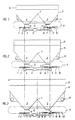
- the centrifugal fertilizer spreader has the support frame 1 with the three-point coupling elements 2, the storage container 3 being fastened in the support frame 1.
- the storage container 3 has the roof-shaped central part 4, whereby the storage container 3 is divided into the funnel-shaped container parts 5 in its lower region. In their lower area, these two funnel-shaped container parts 5 each have the base plates 6, in which the known and therefore not shown outlet opening is arranged. This outlet opening can be adjusted and closed in different opening widths by means of a known slide and therefore not shown in detail. The respective opening width of the outlet opening set by the slide determines the amount of the fertilizer flow flowing from the storage container 3 to the centrifugal discs 7.
- the centrifugal disks 7 arranged on the respective output shaft 8 of the bevel gear 9 distribute the fertilizer particles supplied to them in precisely adjustable amounts by means of the throwing vanes 10 arranged on the centrifugal disks 7.
- the centrifugal disks 7 are driven by the central transmission 11, which is driven by a universal joint shaft from the PTO shaft the tractor which transports the centrifugal fertilizer spreader.
- the stirring shaft 12 protruding into the respective funnel-shaped container part 5 ensures that the fertilizer flow flows uniformly out of the storage container through this respective stirring shaft 12. This stirring shaft 12 is driven in a known manner.
- the angular gear 9 are on the cross member 13 attached, which in turn is connected to the support frame 1.
- the bottom plate 6, which has the outlet opening in the lower region of the respective funnel-shaped container part 5, and the slider, which is arranged under the bottom plate 6 in each case, for adjusting the amount of fertilizer supplied to the centrifugal disc 7, and the agitator shaft 12 represent the metering element of the centrifugal fertilizer spreader arranged centrifugal disks 7 with their throwing blades 10 form the so-called distribution element.
- the individual components of the dosing and distribution elements are arranged in the area K.
- the storage container 3 of the small centrifugal fertilizer spreader according to FIG. 1 has an attachment 14 for increasing its capacity, which can be simply placed on the storage container 3. In this way, the capacity of the storage container 3 can be increased, for example, from 750 l to 1200 l. With the throwing blades 10 of this small centrifugal fertilizer spreader arranged on the centrifugal disks 7, the fertilizer particles can be thrown off, for example, over a working width range of 12 to 18 m.
- FIG. 2 shows a larger centrifugal fertilizer spreader, the term "larger” referring to the capacity of the storage container 15 and to the working width ranges to be sprinkled.
- This storage container 15 is fastened in the support frame 16, the support frame 16 being of a more stable design with respect to the support frame 1 of the centrifugal fertilizer spreader according to FIG. 1, in accordance with the larger capacity of the storage container 15.
- the capacity of the storage container 15 can also be easily increased by attaching the attachment 17 to the storage container 15. For example, it is possible that the storage container 15 has a capacity of 1000 l, which is increased by the attachment 17, for example to 1800 l.
- This storage container 15 also has the roof-shaped central part 4, through which the storage container 15 is divided into the funnel-shaped container parts 5.
- the bottom plate 6, in which the outlet opening is located, is arranged in the lower region of these funnel-shaped container parts 5.
- a slide is arranged below the respective base plates 6, by means of which the outlet opening arranged in the base plate 6 can be adjusted and closed in different opening widths.
- the angular gear 9 are drive-connected to the central gear 11, which can be driven by a PTO shaft of the PTO of the agricultural tractor transporting the centrifugal fertilizer spreader.
- the driven agitator shaft 12 projects into the lower region of the funnel-shaped container parts 5, whereby it is directly above the outlet openings is arranged.
- This centrifugal fertilizer spreader according to FIG. 2 differs only from the centrifugal fertilizer spreader according to FIG. 1 by the large capacity of its storage container 15.
- the components of the metering and distributing members arranged in area K are identical in that The same as the components of the metering and distributing elements of the small centrifugal fertilizer spreader according to FIG. 1.
- the only difference in the distributing elements formed by the centrifugal disc 7 and the throwing vanes 10 is that the throwing blades 10 against the longer length and indicated by dash-dotted lines Throwing blades 18 can be replaced.
- These longer throwing blades 18 can then be used, for example, to hurl the fertilizer particles over a working width range of 20 to 28 m, so that the total working range of this centrifugal fertilizer spreader extends over the working width range from 12 to 28 m.
- the centrifugal fertilizer spreader according to FIG. 3 differs from the centrifugal fertilizer spreader according to FIGS. 1 and 2 only in the larger capacity of its storage container 19.
- the carrying frame 20 is also correspondingly more dimensioned in a corresponding manner due to its larger capacity.
- the capacity of the storage container 19, which can be, for example, 1300 l, can be increased to 2000 l, for example, by attaching the attachment part 21.
- the reservoir 19 of this centrifugal fertilizer spreader also has a roof-shaped middle part 4, whereby the reservoir 19 is divided into the two funnel-shaped container parts 5.
- the bottom plate 6, in which the outlet opening is located, is likewise arranged under these funnel-shaped container parts 5.
- the slide which adjusts and closes the outlet opening 6 in different opening worlds is arranged.
- Feeding fertilizer through the outlet openings of the base plate 6 projects the drivable agitator shaft 12 into the lower region of the respective funnel-shaped container parts 5.
- the fertilizer particles flowing out of the outlet openings reach the centrifugal discs 7 arranged on the output shafts 8 of the angular gear 9 and are distributed by means of the throwing blades 10 arranged on the centrifugal discs 7.
- the angular gear 9 is driven via the central gear 11 by means of a central gear 11 connected to the PTO shaft of the tractor which transports the centrifugal fertilizer spreader.
- the components forming the metering and distributing members are also arranged here in the region K, which is of the same design in all centrifugal fertilizer spreaders of the centrifugal fertilizer spreader series.
- the fertilizer particles can be thrown out by using the long throwing blades 22 over a working range of, for example, 30 to 36 m.
- the throwing blades 18 for the working width range from 20 to 28 m or the throwing blades 10 for the working width range from 12 to 18 m on the centrifugal disc 7, so that the entire working width range from 12 to 36 to be spread with this centrifugal fertilizer spreader m extends.
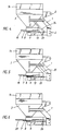
- the possibility of arranging the different throwing blades 10, 18 and 22 results from the arrangement of the guide screens 23 which cooperate with the respective centrifugal discs, which prevent the fertilizer particles to be thrown off by the throwing blades 10, 18 and 22 towards the front Three-point coupling elements 2 are thrown off.
- the different lengths of the throwing blades 10, 18 and 22 therefore require, due to the increasing radius of rotation of the throwing blades, a different size of space for the arrangement of the respective guide screens. This requires design changes to the respective support frame of the centrifugal fertilizer spreader.
- Fig. 4 shows, for example, a centrifugal fertilizer spreader for throwing the fertilizer particles over the working width range from 12 to 18 m, the support frame 1 being designed so that there is only a small free space for the arrangement of the guide plate 23.
- the arrangement of the strut 24 makes it possible to design the support frame 1 in a particularly light construction, so that there is an inexpensive solution for producing a centrifugal fertilizer spreader.
- the centrifugal fertilizer spreader must have adequate space for arranging the guide plate 23 at a different distance from the centrifugal disk drive shaft 8 or by exchanging the guide screen for one differently designed guide screen, so that the use of the longer throwing blades 18 is possible.
- the arrangement of the guide screen 23 at a different distance from the centrifugal disc drive shaft 8 requires a different design of the support frame 1, the support frame 1 being reinforced by means of the strut 25.
- Special design measures with regard to the design of the support frame 1 of the small centrifugal fertilizer spreader can also be used to arrange the large throwing blades 22 on the centrifugal disc 7, which also makes it possible with the small centrifugal fertilizer spreader to spread the fertilizer particles over the large working width range of 30 to 36 m and thus also to be thrown over the entire working width range from 12 to 36 m.
- the support frame 1 must be designed such that there is a large free space for the arrangement of the guide screen 26 cooperating with the long throwing blades 22. This requires a more stable design of the support frame 1.
- the area K in which the metering and distributing members are arranged, in all centrifugal fertilizer spreader types, ie in the small, in the medium-sized, even with the large centrifugal fertilizer spreader, is of the same design, this results in an extremely economical system for creating a centrifugal fertilizer spreader series.
- the metering and distributing elements arranged in area K can also be arranged as a spreading unit on a large-area fertilizer spreader.
Landscapes
- Life Sciences & Earth Sciences (AREA)
- Soil Sciences (AREA)
- Environmental Sciences (AREA)
- Fertilizing (AREA)
Claims (4)
- Série d'épandeurs centrifuges d'engrais comprenant des épandeurs centrifuges d'engrais ayant des capacités différentes, notamment des capacités petites, moyennes et grandes et/ou une résistance correspondante, les épandeurs centrifuges comportant un châssis (1), un réservoir d'alimentation (3, 15, 19), des écrans de guidage, des organes de dosage réglable ainsi que des organes de distribution en forme de disques d'épandage entraînés équipés d'organes d'éjection, caractérisée en ce que les épandeurs centrifuges sont prévus pour des plages de largeurs de travail différentes et en ce que la plage K dans laquelle se trouvent les organes de dosage et de distribution, est réalisée sur le plan constructif, identique au montage des organes de dosage (6) pour les organes de distribution (7) de chaque épandeur centrifuge pour des plages de largeurs de travail différentes, les organes de distribution pouvant être échangés pour atteindre des plages de largeurs de travail différentes et en ce que pour l'épandeur correspondant à la plus grande dimension de la série, les organes de distribution (7) sont prévus pour au moins trois plages de largeurs de travail qui servent chaque fois de manière inchangée pour l'épandeur avec les valeurs de réglage pour la petite et la moyenne plages de largeurs de travail.
- Série constructive selon la revendication 1, caractérisée en ce que les disques d'épandage (7) et/ou leurs palettes d'éjection (10, 18, 22) sont réalisés facilement amovibles et échangeables.
- Série constructive selon la revendication 2, caractérisée ne ce que les palettes de guidage (23, 26) sont fixées à des distances différentes de l'axe d'entraînement (8) des disques d'épandage sur l'épandeur.
- Série constructive selon la revendication 2, caractérisée en ce que les écrans de guidage (23, 26) peuvent être remplacés par d'autres écrans de guidage.
Applications Claiming Priority (2)
| Application Number | Priority Date | Filing Date | Title |
|---|---|---|---|
| DE3907010 | 1989-03-04 | ||
| DE3907010A DE3907010A1 (de) | 1989-03-04 | 1989-03-04 | System zur erstellung einer schleuderduengerstreuerbaureihe |
Publications (2)
| Publication Number | Publication Date |
|---|---|
| EP0386540A1 EP0386540A1 (fr) | 1990-09-12 |
| EP0386540B1 true EP0386540B1 (fr) | 1994-11-30 |
Family
ID=6375552
Family Applications (1)
| Application Number | Title | Priority Date | Filing Date |
|---|---|---|---|
| EP90103484A Expired - Lifetime EP0386540B1 (fr) | 1989-03-04 | 1990-02-23 | Système de fabrication d'une série d'épandeurs de capacité croissante |
Country Status (4)
| Country | Link |
|---|---|
| EP (1) | EP0386540B1 (fr) |
| CZ (1) | CZ282362B6 (fr) |
| DE (2) | DE3907010A1 (fr) |
| HU (1) | HU205229B (fr) |
Families Citing this family (1)
| Publication number | Priority date | Publication date | Assignee | Title |
|---|---|---|---|---|
| EP0870422A3 (fr) * | 1997-04-10 | 1998-12-02 | Amazonen-Werke H. Dreyer GmbH & Co. KG | Epandeur centrifuge d'engrais |
Family Cites Families (5)
| Publication number | Priority date | Publication date | Assignee | Title |
|---|---|---|---|---|
| DE1457769A1 (de) * | 1965-04-29 | 1969-05-29 | Amazonen Werke Dreyer H | Zentrifugalstreuer,insbesondere zum Ausstreuen von Mineralduengemitteln |
| DE1557961A1 (de) * | 1966-09-16 | 1970-05-21 | Dreyer Heinrich Wilhelm | Vorrichtung zum Ausstreuen von pulvrigem oder gekoerntem Gut |
| NL8500759A (nl) * | 1985-03-15 | 1986-10-01 | Lely Nv C Van Der | Inrichting voor het verspreiden van korrelen/of poedervormig materiaal. |
| DE3533586A1 (de) * | 1985-09-20 | 1987-04-02 | Amazonen Werke Dreyer H | Maschine zum ausbringen von koernigem material |
| DE3722507A1 (de) * | 1987-07-08 | 1989-01-19 | Amazonen Werke Dreyer H | Zentrifugalduengerstreuer |
-
1989
- 1989-03-04 DE DE3907010A patent/DE3907010A1/de not_active Withdrawn
-
1990
- 1990-02-08 HU HU90713A patent/HU205229B/hu not_active IP Right Cessation
- 1990-02-23 DE DE59007788T patent/DE59007788D1/de not_active Expired - Fee Related
- 1990-02-23 EP EP90103484A patent/EP0386540B1/fr not_active Expired - Lifetime
- 1990-02-27 CZ CS90917A patent/CZ282362B6/cs unknown
Also Published As
| Publication number | Publication date |
|---|---|
| HUT56218A (en) | 1991-08-28 |
| HU205229B (en) | 1992-04-28 |
| HU900713D0 (en) | 1990-04-28 |
| CZ282362B6 (cs) | 1997-07-16 |
| EP0386540A1 (fr) | 1990-09-12 |
| DE3907010A1 (de) | 1990-09-06 |
| CS9000917A2 (en) | 1991-08-13 |
| DE59007788D1 (de) | 1995-01-12 |
Similar Documents
| Publication | Publication Date | Title |
|---|---|---|
| DE3529452A1 (de) | Streugeraet | |
| EP0540889B2 (fr) | Epandeur d'engrais centrifuge | |
| EP0820219B1 (fr) | Epandeur d'engrais centrifuge | |
| EP0545894B2 (fr) | Epandeur centrifuge | |
| DE3337762C2 (de) | Schleuderstreuer | |
| EP0559242B1 (fr) | Expandeur centrifuge | |
| EP0242749B2 (fr) | Distributeur à disques | |
| EP0292874B1 (fr) | Distributeur à grand tonnage | |
| EP0216058B1 (fr) | Epandeur de granulés | |
| EP1078564B1 (fr) | Epandeur d'engrais centrifuge | |
| DE3739265A1 (de) | Schleuderstreuer | |
| EP0386540A1 (fr) | Système de fabrication d'une série d'épandeurs de capacité croissante | |
| EP0910939A1 (fr) | Epandeur centrifuge | |
| EP0809427B1 (fr) | Epandeur centrifuge pour engrais | |
| DE19606586A1 (de) | Schleuderdüngerstreuer | |
| EP0870423A1 (fr) | Méthode pour déposer un seul fertilisant, ou bien plusieurs en même temps, avec un épandeur d'engrais | |
| EP0356770B1 (fr) | Distributeurs centrifuges d'engrais | |
| DE3917210A1 (de) | Schleuderduengerstreuer | |
| DE3901523A1 (de) | Schleuderduengerstreuer | |
| DD297905A5 (de) | Schleuderduengerstreuer | |
| DE202025100088U1 (de) | Schleuderstreuer mit einem eine Querwelle umfassenden Antriebsstrang zum Antrieb der Verteilerscheiben | |
| DE3608935A1 (de) | Schleuderstreuer | |
| DE3917449C2 (fr) | ||
| EP0904682A1 (fr) | Epandeur centrifuge | |
| DE10033674A1 (de) | Schleuderdüngerstreuer |
Legal Events
| Date | Code | Title | Description |
|---|---|---|---|
| PUAI | Public reference made under article 153(3) epc to a published international application that has entered the european phase |
Free format text: ORIGINAL CODE: 0009012 |
|
| AK | Designated contracting states |
Kind code of ref document: A1 Designated state(s): DE FR GB |
|
| 17P | Request for examination filed |
Effective date: 19901127 |
|
| 17Q | First examination report despatched |
Effective date: 19911122 |
|
| GRAA | (expected) grant |
Free format text: ORIGINAL CODE: 0009210 |
|
| AK | Designated contracting states |
Kind code of ref document: B1 Designated state(s): DE FR GB |
|
| ET | Fr: translation filed | ||
| GBT | Gb: translation of ep patent filed (gb section 77(6)(a)/1977) |
Effective date: 19941202 |
|
| REF | Corresponds to: |
Ref document number: 59007788 Country of ref document: DE Date of ref document: 19950112 |
|
| PLBE | No opposition filed within time limit |
Free format text: ORIGINAL CODE: 0009261 |
|
| STAA | Information on the status of an ep patent application or granted ep patent |
Free format text: STATUS: NO OPPOSITION FILED WITHIN TIME LIMIT |
|
| 26N | No opposition filed | ||
| PGFP | Annual fee paid to national office [announced via postgrant information from national office to epo] |
Ref country code: GB Payment date: 19960119 Year of fee payment: 7 |
|
| PGFP | Annual fee paid to national office [announced via postgrant information from national office to epo] |
Ref country code: FR Payment date: 19960202 Year of fee payment: 7 |
|
| PG25 | Lapsed in a contracting state [announced via postgrant information from national office to epo] |
Ref country code: GB Effective date: 19970223 |
|
| GBPC | Gb: european patent ceased through non-payment of renewal fee |
Effective date: 19970223 |
|
| PG25 | Lapsed in a contracting state [announced via postgrant information from national office to epo] |
Ref country code: FR Effective date: 19971030 |
|
| REG | Reference to a national code |
Ref country code: FR Ref legal event code: ST |
|
| PGFP | Annual fee paid to national office [announced via postgrant information from national office to epo] |
Ref country code: DE Payment date: 19980212 Year of fee payment: 9 |
|
| PG25 | Lapsed in a contracting state [announced via postgrant information from national office to epo] |
Ref country code: DE Free format text: LAPSE BECAUSE OF NON-PAYMENT OF DUE FEES Effective date: 19991201 |