EP0263666A2 - Schnurloses Fernsprechgerät - Google Patents
Schnurloses Fernsprechgerät Download PDFInfo
- Publication number
- EP0263666A2 EP0263666A2 EP87308813A EP87308813A EP0263666A2 EP 0263666 A2 EP0263666 A2 EP 0263666A2 EP 87308813 A EP87308813 A EP 87308813A EP 87308813 A EP87308813 A EP 87308813A EP 0263666 A2 EP0263666 A2 EP 0263666A2
- Authority
- EP
- European Patent Office
- Prior art keywords
- pager
- signal
- parent device
- radio telephone
- telephone
- Prior art date
- Legal status (The legal status is an assumption and is not a legal conclusion. Google has not performed a legal analysis and makes no representation as to the accuracy of the status listed.)
- Granted
Links
Images








Classifications
-
- H—ELECTRICITY
- H04—ELECTRIC COMMUNICATION TECHNIQUE
- H04M—TELEPHONIC COMMUNICATION
- H04M1/00—Substation equipment, e.g. for use by subscribers
- H04M1/26—Devices for calling a subscriber
-
- H—ELECTRICITY
- H04—ELECTRIC COMMUNICATION TECHNIQUE
- H04M—TELEPHONIC COMMUNICATION
- H04M1/00—Substation equipment, e.g. for use by subscribers
- H04M1/72—Mobile telephones; Cordless telephones, i.e. devices for establishing wireless links to base stations without route selection
- H04M1/725—Cordless telephones
- H04M1/72502—Cordless telephones with one base station connected to a single line
- H04M1/72516—Cordless telephones with one base station connected to a single line with means for out-of-range alerting
-
- H—ELECTRICITY
- H04—ELECTRIC COMMUNICATION TECHNIQUE
- H04M—TELEPHONIC COMMUNICATION
- H04M1/00—Substation equipment, e.g. for use by subscribers
- H04M1/72—Mobile telephones; Cordless telephones, i.e. devices for establishing wireless links to base stations without route selection
- H04M1/725—Cordless telephones
- H04M1/72502—Cordless telephones with one base station connected to a single line
- H04M1/72505—Radio link set-up procedures
Definitions
- This invention relates to a cordless telephone apparatus, and particularly to a cordless telephone apparatus which has a pager which reports an incoming call from a parent device or a radio telephone.
- an apparatus of this type has a structure, for example, shown in Fig. 13 in which a parent device 1 is connected via a radio channel with a radio telephone 2 and also connected with a subscriber's line 3.
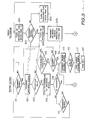
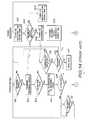
- the apparatus When the apparatus received a calling signal from the subscriber's line 3, it provides the control shown in a flowchart of Fig. 14.
- the calling signal is input via a hybrid circuit 4 to a calling signal detector (not shown) which then detects it and delivers its detection output to a control circuit 5.
- the control circuit 5 receives this detection output, it determines that there is an incoming call (step 101) and sets a synthesizer 6 at the frequency of a control channel.
- the control circuit 5 indicates an empty communication channel and applies the incoming signal, inclusive of an identification signal ID, to a transmitter 7 to thereby cause the transmitter 7 set in the control channel to transmit the incoming signal via a transmission antenna 8 (step 102).
- a synthesizer 10 is set at the frequency of the control channel.
- the synthesizer 10 and a receiver 11 are turned on for a time t1 (step 201), and then turned off for a time t2 (step 202), which is repeated.
- the receiver 11 When the receiver 11 is on and receives the incoming signal via a reception antenna 12 (step 203), it delivers this signal to an identification signal detector 13 and a reception field detector 14.
- the identification signal detector 13 identifies an identification (ID) signal contained in the incoming signal and the reception field detector 14 detects the presence of a reception field, the control circuit 15 turns on a transmitter 16 (step 204).
- ID identification
- the control circuit 15 applies a signal responsive to an incoming signal, inclusive of the ID signal, to the transmitter 16 to cause same to transmit the responsive signal via a transmission antenna 17 (step 205). Thereafter, the control circuit 15 switches the synthesizer 10 from the frequency of the control channel to the frequency of the telephonic communication channel (step 206).
- the receiver 18 in the parent device 1 receives the responsive signal via its reception antenna 19, it delivers the responsive signal to the identification signal detector 20 and reception field detector 21.
- the control circuit 5 causes the transmission of the incoming signal from being stopped (step 104).
- the control circuit 5 When no reception field is detected at the step 103, the control circuit 5 causes the incoming signal to be transmitted repeatedly and when the number of transmissions reaches n (step 105), the control circuit 5 causes the transmission of the incoming signal to be stopped in order to avoid the unnecessary use of the control channel. If at this time the calling signal continues to be still transmitted (step 106), a sounder (not shown) of the parent device 1 is rung (step 107).
- the identification signal detector 20 identifies the ID signal contained in the incoming signal (step 108)
- the control circuit switches the synthesizer 6 from the frequency of the control channel to the frequency of an empty telephonic communication channel (step 109).
- the control circuit 5 waits until it fails to receive a calling signal from the telephone circuit 3 (step 110).
- the control circuit 5 delivers a bell ringing signal to the transmitter 7 set to the telephonic communication channel to cause the transmitter to transmit the bell ringing signal via the transmission antenna 8 (step 111).
- the receiver 11 in the radio telephone 2 receives this signal via the reception antenna 12 (step 201), it delivers the signal to the control circuit 15 which, in response to this signal, rings a sounder 23 (step 208).
- the control circuit 15 determines whether or not the hook switch, not shown, is switched on (step 209), and if the hook switch is on, the control circuit 15 causes the transmitter 16 to transmit a signal indicative of the unhooking via the transmission antenna 17 (step 210).
- a radio telephone 2 is brought to a telephonic communication state (step 211), so that telephonic communication is possible over a telephone receiver 24 and a telephone transmitter 25.
- the receiver 18 in the parent device 1 receives the unhooking signal via the reception antenna 19 (step 112), it delivers this signal to the control circuit 5 which, in response to this signal, causes the transmission of the bell ringing signal to be stopped (step 113). This causes the parent device 1 to be also put to a telephonic communication state (step 114).
- the telephonic communication channel has a wide baseband zone, for example, of 3 KHz, to permit vocal transmission and requires a high field strength, for example, of 40 dB uV/m or more to maintain high S/N.
- the service area for the cordless telephone apparatus is limited to a relatively narrow range, for example, of 20 meters.
- the transmission output power could be increased so as to expand the service area, which, however, would undesirably increase the current consumption at the radio telephone to shorten the battery life and easily interfer with other cordless telephone apparatuses.
- the power source of the radio telephone is switched off and the parent device rings a calling sound. When the radio telephone becomes distant from the parent device, however, it cannot hear the calling sound.
- the radio telephone is usually too large and weighty to carry.
- the radio telephone could be miniaturized, which would, however, increase the cost as well as require miniaturization of the batteries used to thereby shorten the battery life.
- the radio telephone when there is an incoming signal or call at the radio telephone and the radio telephone is outside the service area for the telephonic communication channel, the radio telephone cannot receive a bell ringing signal, so that it cannot notice that it is being called.
- the radio telephone is large-sized and weighty, so that it is poorly suitable for portableness and is not functional.
- the cordless telephone apparatus includes a pager which is started by a signal delivered via a radio channel from a parent device or radio telephone.
- the pager is started by a signal delivered via a radio channel from the parent or the radio telephone.
- Fig. 1 is a block diagram showing a first embodiment of a cordless telephone apparatus according to this invention.
- This embodiment includes a modification of the conventional apparatus shown in Fig. 13 obtained by providing a pager 31, connecting a pager transmitter 32 with the control circuit 5 of the parent device 1, and providing a pager transmission antenna 33 to the pager transmitter 32.
- the pager 31 is also called a pocket bell and is small-sized, easy to carry and used only for reporting using alarm sound or light flashing.
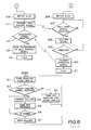
- the control shown in the flowchart of Fig. 2 is provided.
- the control circuit 5 determines that there is an incoming signal (step 101), and causes the transmitter 7 to transmit the incoming signal via the transmission antenna 8 (step 102) and delivers a pager calling signal to the pager transmitter 32.
- the pager transmitter 32 receives this signal, it transmits the signal via a preset pager channel and a pager transmission antenna 33 (step 121).
- the pager 31 turns on the receiver 34 for a time t3 (step 301) and then turns off the receiver for a time t4 (step 302), which is repeated.
- the receiver 34 is set in advance in the pager channel.
- the control circuit 36 which, in response to this signal, delivers a reporting vocal signal to a sounder 37 to cause same to ring as well as to cause an electric current to flow intermittently through a light emitting diode 38 to flash same. Therefore, the pager 31 reports a call from the parent device 1 (step 304).
- an incoming signal is noticed at the radio telephone 2 from the reporting by the pager 31 or the ringing of the telephone sounder 23, and if the telephone 2 is unhooked (step 209), a signal indicative of this unhooking is transmitted (step 210).
- the control circuit 5 causes the transmission of a bell ringing signal to be stopped (step 112) and causes the transmission of the pager calling signal from the pager transmitter 32 to be stopped (step 122).
- the pager 31 fails to receive the pager calling signal (step 305) and stops a report showing the call from the patent device 1 (step 306).
- the pager channel connecting the parent device 1 and pager 31 only carries the pager calling signal, so that it may be of a narrow zone and hence can carry the pager calling signal to a distant pager 31 even if the transmission power output from the parent device 1 is small.
- the pager 31 is used only in the pager channel, so that it may be simple in structure, low in power consumption and easy to miniaturized. Therefore, if the user carries the pager 31 around, he can easily notice an incoming signal, if any, even if he is distant from the parent device 1.
- a switch is provided at the pager 31 to stop pager's reporting so as to avoid an unnecessary operation of the sounder 37 and light emitting diode 38.
- the flowchart of Fig. 3 shows another control process at the apparatus of the embodiment shown in Fig. 1.
- the parent device 1 when it does not receive a response indicative of reception from the radio telephone 2 even if it transmits the incoming signal, it transmits a pager calling signal to the pager 31.
- the control circuit 5 in the parent device 1 causes the transmission of the incoming signal to be stopped. If at this time the parent device continues to receive the calling signal (step 106), the control circuit causes the pager transmitter 32 to transmit the pager calling signal via the pager transmission antenna 33 (step 115). When a preset time 2 ⁇ t3 + t4 has passed (step 116), the control circuit 5 causes the transmission of the pager calling signal to be stopped (step 117) and causes the sounder (not shown) in the parent device 1 to ring (step 107).
- the receiver 34 is turned on for a time t3 (step 311) and then turned off for a time t4 (step 312), which is repeated.
- the on-off period of the receiver 31 is a time t3 + t4, so that it is a time t3 shorter than the transmission time 2 ⁇ t3 + t4 of the pager calling signal transmitted from the parent device 1 and, therefore, the pager calling signal is received reliably.
- the receiver 34 When the receiver 34 is on and receives this pager calling signal via the reception antenna 35 (step 313), it applies the pager calling signal to the control circuit 36 which, in response to this signal, rings the sounder 37 as well as flashes the light emitting diode 38 to thereby report the calling from the parent device 1 (step 314).
- the control circuit 36 turns off the receiver 34 (step 315), and when a preset time t5 has passed (step 316), the control circuit causes the ringing of the sounder 37 and the flashing of the diode 38 to be stopped thereby to stop the reporting of the calling (step 313).
- Fig. 4 is a block diagram showing a second embodiment of the cordless telephone apparatus according to this invention.
- This invention includes the conventional apparatus shown in Fig. 13 and a pager 31.
- the apparatus When there is an incoming signal and the apparatus receives a calling signal via the telephone circuit 3, the apparatus provides the control shown in the flowchart of Fig. 5.
- the control circuit 5 in the parent device 1 determines that there is an incoming signal (step 101), it sets the synthesizer 6 at the frequency of the pager channel set in advance and then applies a pager calling signal to the transmitter 7 which, in response to this signal, transmits this signal via the pager channel and the transmission antenna 8 (step 131).
- the control circuit 5 then waits until the time t3 + t4 has passed (step 132). When this time has passed, the control circuit causes the transmission of the pager calling signal to be stopped (step 133). Thereafter, the control circuit 5 switches the synthesizer 6 from the frequency of the pager channel to the frequency of the control channel to thereby causes the incoming signal to be transmitted (step 102).
- the receiver 34 is turned on for a time t3 (step 311) and then turned off for a time t4 (step 312), which is repeated.
- the receiver 34 is set in advance in the pager channel, and when it is on and receives the pager calling signal via the reception antenna 35 (step 313), it applies this signal to the control circuit 36 which, in response to this signal, causes the sounder 37 to ring as well as to flash the light emitting diode 38 to thereby cause the calling from the parent device 1 to be reported (step 314).
- control circuit 36 turns off the receiver 34 (step 315), and when a time t5 has passed (step 316), the control circuit 36 causes the ringing of the sounder 37 and the flashing of the diode 38 to be stopped thereby stop the reporting of the calling (step 317).
- this embodiment lacks elements such as the pager transmitter 32 and pager transmission antenna 33 of the parent device 1 shown in Fig. 1, so that the structure of the parent device 1 is less complicated.
- the incoming signal is transmitted by the parent device 1 after the transmission time 2 ⁇ t3 + t4 of the pager calling signal, there is substantially no problem if the on-off period t3 + t4 of the receiver 34 at the pager 31 is selected short enough compared to the on-off period t1 + t2 of the receiver 11 at the radio telephone 2.
- the pager 31 uses the receiver 34 having a signal channel without a synthesizer, so that power consumption is very low.
- the power consumption of the pager 31 is about 5 mA and that of the radio telephone 2 is about 50 mA. Therefore, Even if t3/(t3 + t4) is selected to be 10 times (t1 + t2), the entire current consumption during standby is the same.
- a switch 39 is provided in the pager 31 for stopping the reporting so as to avoid unnecessary ringing of the sounder 37.
- the flowchart of Fig. 6 illustrates another control process at the apparatus of the embodiment shown in Fig. 4. While the incoming signal has been transmitted delayed by the time 2 ⁇ t3 + t4 in the flowchart of Fig. 5, it is arranged that such does not occur in the flowchart of Fig. 6.
- the parent device 1 when the parent device 1 transmits the incoming signal via the control channel (step 102), it determines whether or not there is a reception field from the radio telephone 2 (step 103). If, for example, there is a reception field by transmitting an incoming signal only once, the parent device 1 determines whether or not the frequency of transmitting the incoming signal has reached m ( ⁇ n) (step 141). Since the frequency has not reached m now, the incoming signal is again transmitted (step 142), which is repeated up to m times.
- the receiver 34 is turned on for a time t3 (311) and then turned off for a time t4 (step 312), which is repeated.
- the receiver 34 is set in advance to the control channel, receives the incoming signal during a period t3 + t4 shorter than the time during which the incoming signal is transmitted m times (step 321), and applies this incoming signal to the control circuit 36 which, in response to this signal, rings the sounder 37 as well as flashes the diode 38 (step 314).
- the control circuit 36 then switches off the receiver 34 (step 315) and, after a time t5 has passed (step 316), the control circuit causes the ringing of the sounder 37 and the flashing of the diode 38 to be stopped (step 317).
- the radio telephone 2 When the radio telephone 2 receives the incoming signal (step 203), it turns on the transmitter 16 (step 204) and waits until the incoming signal is no longer received (step 215) after which the telephone 2 transmits a signal responsive to the incoming signal (step 205).
- the pager 31 is started when it receives the incoming signal transmitted by the parent device 1, so that there is no delayed transmission of the incoming signal.
- the control channel is not used for communication of a vocal signal, so that it may be of a narrow zone and hence the pager 31 can receive the incoming signal and reports it even if the pager 31 is distant from the parent device 1.
- the flowchart of Fig. 7 illustrates another control process at the apparatus of the embodiment showing in Fig. 4 in which when the radio telephone 2 receives an incoming signal from the parent device 1 and transmits this signal, it transmits a pager calling signal to the pager 31.
- the control circuit 15 transmits a pager calling signal from the transmitter 16 via the transmission antenna 17 (step 221).
- the control circuit 15 causes the transmission of the pager calling signal to be stopped (step 223) and switches the synthesizer 10 from the frequency of the control channel to the frequency of the telephonic communication channel (step 206).
- the receiver 34 in the pager 31 when the receiver 34 in the pager 31 is on and receives the pager calling signal (step 313), it applies the pager calling signal to the control circuit 36 which, in response to this signal, rings the sounder 37 as well as flashes the light emitting diode 38 (step 314).
- the control circuit 36 then turns off the receiver 34 (step 315) and when a time t5 has passed (step 316), the control circuit 36 causes the ringing of the sounder 37 and the flashing of the diode 38 to be stopped (step 317).
- the standby period t1 + t2 and t3 + t4 in the radio telephone and the pager, respectively, described with reference to the flowcharts of Figs. 2, 3, 5, 6 and 7 may not be fixed.
- the radio telephone and pager may have a function to extend their respective periods.
- Fig. 8 is a block diagram showing a third embodiment of a cordless telephone apparatus according to this invention.
- a microswitch 53 (normally open) is connected in series with a manual switch 52 which connects and disconnects the power source 51 of the radio telephone 2, and also connected in parallel with a switch 55 which interlocks with a manual switch 54.
- the power source 51 supplies power via the switches 52 and 53.
- the microswitch 53 is switched off to stop power supply from the power source 51.
- the radio telephone 2 will not operate and only the pager 31 will operate. Since the radio telephone 2 has the pager 31 mounted thereon, the pager 31 can report a call from the parent device 1 even when there is an incoming signal if the radio telephone 2 does not operate.
- the manual switch 54 may be switched on to switch on the switch 55 to thereby start to supply power to the telephone 2 for operating purposes.
- a DC voltage power supply circuit including a transformer 61, a rectifier 62 and a regulator 63 converts a commercially available AC voltage of 100 V to a direct current voltage of 5 V which is then fed, so that it is unnecessary to especially save the battery.
- Fig. 10 is a block diagram showing a fourth embodiment of a cordless telephone apparatus according to this invention.
- the parent device 1 of this embodiment includes a direct current voltage supply circuit which in turn includes transformer 61, rectifier 62 and regulator 63 and an external terminal 64 to which the direct current voltage output from the direct current voltage supply circuit is applied, and an external terminal 65 at ground potential.
- the pager 31 includes a secondary battery 66 as a power supply, a diode 67 for preventing a reverse current, an external terminal 68 connected via the diode 67 to the secondary battery 66 and an external terminal 69 at ground potential.
- the direct current voltage output from the direct current voltage supply circuit is supplied via the external terminals 64, 68 and diode 67 to the secondary battery 66 to charge same. Therefore, the battery 66 is easily charged, so that the small-sized secondary battery may be used to miniatuarize the pager 31 easily. If the secondary battery 66 is miniaturized, the charging current is small, so that when the pager 31 is mounted on the radio telephone 2 in the embodiment shown in Fig. 8, the secondary battery 66 may be connected to the power source of the radio telephone 2 for charging purposes. Instead of the secondary battery 66, a solar cell may be used.
- Fig. 11 shows a block diagram showing a fifth embodiment of the cordless telephone apparatus according to this invention.
- the parent device 1 includes the parent device 1 shown in Fig. 1 and a pager calling switch 71 provided thereon while radio telephone 2 includes the telephone 2 and a pager calling switch 72 provided thereon.
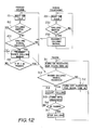
- This embodiment provides the control shown in the flowchart of Fig. 12.
- the control circuit 15 causes the transmitter 16 to transmit a pager calling signal via the transmission antenna 17 (step 233).
- the control circuit 5 causes the pager transmitter 32 to transmit a pager calling signal via the pager transmission antenna 33 (step 154) and causes this transmission to be stopped after a time 2 t3 + t4 has passed (step 155).
- the control circuit 36 causes the sounder 37 to ring and causes the light emitting diode 38 to flash (step 314) and when a time t5 has passed (step 316), the control circuit 36 causes the sounder 37 and diode 38 to stop their ringing and flashing, respectively, (step 317).
- the pager 31 receives a call from the parent device 1 or the radio telephone 2. It would be convenient if the calling from the parent device 1 when there is an incoming signal, the calling from the radio telephone 2 by the switching on of the pager calling switch 72, and the calling from the parent device 1 by the switching on of the pager calling switch 71 can be discriminated one from the other using the reporting by the pager 31. To this end, pager calling signals indicative of these respective cases are predetermined. When the pager 31 receives these respective pager calling signals, the control circuit 36 discriminates the respective cases.
- the pager 31 when there is an incoming signal and the pager 31 is called from the parent device 1, it causes the sounder 37 and diode 38 to operate for one second at intervals of one second.
- the control circuit 36 may cause the sounder 37 and diode 38 to operate continuously.
- the control circuit 36 may cause the light emitting diode 38 to operate for 0.5 seconds at intervals of 0.5 seconds.
- the pager 31 may have a liquid crystal display which displays the above respective cases thereon using characters and continues such display for a predetermined set time after the reporting is completed, which further facilitates the discrimination.
Landscapes
- Engineering & Computer Science (AREA)
- Signal Processing (AREA)
- Computer Networks & Wireless Communication (AREA)
- Mobile Radio Communication Systems (AREA)
Applications Claiming Priority (2)
| Application Number | Priority Date | Filing Date | Title |
|---|---|---|---|
| JP237624/86 | 1986-10-06 | ||
| JP61237624A JPS6392132A (ja) | 1986-10-06 | 1986-10-06 | コ−ドレス電話装置 |
Publications (3)
| Publication Number | Publication Date |
|---|---|
| EP0263666A2 true EP0263666A2 (de) | 1988-04-13 |
| EP0263666A3 EP0263666A3 (en) | 1989-05-24 |
| EP0263666B1 EP0263666B1 (de) | 1994-12-21 |
Family
ID=17018075
Family Applications (1)
| Application Number | Title | Priority Date | Filing Date |
|---|---|---|---|
| EP87308813A Expired - Lifetime EP0263666B1 (de) | 1986-10-06 | 1987-10-05 | Schnurloses Fernsprechgerät |
Country Status (5)
| Country | Link |
|---|---|
| US (1) | US5040204A (de) |
| EP (1) | EP0263666B1 (de) |
| JP (1) | JPS6392132A (de) |
| KR (1) | KR900009143B1 (de) |
| DE (1) | DE3750896T2 (de) |
Cited By (17)
| Publication number | Priority date | Publication date | Assignee | Title |
|---|---|---|---|---|
| US4962528A (en) * | 1989-05-22 | 1990-10-09 | Herrera Juan H | Beeper amplifier |
| GB2234649A (en) * | 1989-04-27 | 1991-02-06 | Stc Plc | Personal communications systems |
| WO1991012673A1 (en) * | 1990-02-09 | 1991-08-22 | Motorola, Inc. | Radio telephone with detachable selective call receiver |
| WO1991014332A1 (en) * | 1990-03-05 | 1991-09-19 | Motorola, Inc. | Radio telephone with secondary charging capability |
| GB2250890A (en) * | 1990-09-26 | 1992-06-17 | Plessey Telecomm | Cordless telephone communication system |
| US5247700A (en) * | 1990-11-16 | 1993-09-21 | Universal Cellular, Inc. | Cellular telephone with pager |
| EP0554349A4 (en) * | 1990-10-24 | 1993-10-13 | Motorola, Inc. | Carry case assembly for a portable electrical device |
| US5392452A (en) * | 1992-11-27 | 1995-02-21 | Motorola, Inc. | Selective call signaling system with combined wide area paging and high data rate transmissions via radio telephone transceivers |
| EP0674417A3 (de) * | 1994-03-25 | 1995-11-08 | Nec Corp | |
| EP0746131A1 (de) * | 1995-06-03 | 1996-12-04 | Tonami Electronics Corporation | Funkkommunikationsgerät |
| WO1997011532A1 (en) * | 1995-09-18 | 1997-03-27 | Casio Computer Co., Ltd. | Incoming calling system |
| EP0746132A3 (de) * | 1995-05-30 | 1998-04-22 | Nec Corporation | Personenrufsystem für ein schnurloses Telefon |
| GB2324227A (en) * | 1997-02-26 | 1998-10-14 | Motorola Inc | Modular communication device |
| GB2325591A (en) * | 1997-04-01 | 1998-11-25 | Motorola Inc | Multi-mode radio telephone having a multiple battery arrangement |
| US5845202A (en) * | 1992-11-27 | 1998-12-01 | Motorola, Inc. | Method and apparatus for acknowledge back signaling using a radio telephone system |
| US5907615A (en) * | 1992-12-02 | 1999-05-25 | Motorola, Inc. | Miniature wireless communication device |
| RU2159012C2 (ru) * | 1997-06-05 | 2000-11-10 | Моторола, Инк. | Устройство связи, имеющее несколько индикаторов (варианты) |
Families Citing this family (45)
| Publication number | Priority date | Publication date | Assignee | Title |
|---|---|---|---|---|
| US7106819B1 (en) * | 1987-11-20 | 2006-09-12 | Interdigital Technology Corporation | Plural subscriber system utilizing synchronized timeslots on a single frequency |
| US4989230A (en) * | 1988-09-23 | 1991-01-29 | Motorola, Inc. | Cellular cordless telephone |
| JPH0773385B2 (ja) * | 1989-04-03 | 1995-08-02 | 三菱電機株式会社 | 移動電話装置 |
| JPH03147431A (ja) * | 1989-11-02 | 1991-06-24 | Toshiba Corp | 選択呼出受信機およびそのメッセージ消去方法 |
| US5117449A (en) * | 1989-11-03 | 1992-05-26 | Motorola, Inc. | Dual receiver apparatus for integrated paging and radiotelephone functions |
| JPH03187655A (ja) * | 1989-12-18 | 1991-08-15 | Toshiba Corp | 無線電話装置 |
| US5890073A (en) * | 1990-06-20 | 1999-03-30 | Any Co. Ltd. | Mobile terminal capable of sending communication mode signals and a method thereof |
| JPH0439755U (de) * | 1990-07-31 | 1992-04-03 | ||
| US5153903A (en) * | 1990-11-05 | 1992-10-06 | Motorola, Inc. | Integrated paging and radiotelephone system having improved paging reliability |
| DE69225925T2 (de) * | 1991-04-17 | 1998-10-22 | Ericsson Telefon Ab L M | Zellulares Kommunikationssystem mit integrierten Funkrufsystem |
| US6259929B1 (en) * | 1991-05-30 | 2001-07-10 | Nokia Mobile Phones Limited | Radio phone composable of separate modules |
| US5148473A (en) * | 1991-08-30 | 1992-09-15 | Motorola, Inc. | Pager and radiotelephone apparatus |
| TW198141B (de) * | 1991-09-16 | 1993-01-11 | Motorola Inc | |
| AU2513492A (en) * | 1991-09-30 | 1993-05-03 | Motorola, Inc. | Cordless telephone system with inbound calling |
| SE469865B (sv) * | 1992-02-17 | 1993-09-27 | Ericsson Telefon Ab L M | Sätt att etablera samarbete med en funktionalitet samt anordning för utövande av sättet |
| KR0150247B1 (ko) * | 1993-02-25 | 1998-11-02 | 안쏘니 제이. 살리, 주니어 | 외부 안테니가 은폐된 수신기 |
| US6009309A (en) * | 1993-05-04 | 1999-12-28 | Motorola, Inc. | Method of operation a combination radiotelephone and paging device and method of operation |
| CA2130507A1 (en) * | 1993-11-19 | 1995-05-20 | Bernard M. Snyder | System and method for remotely tripping a switch |
| US5588038A (en) * | 1993-11-19 | 1996-12-24 | J.F.A. Tech., Inc. | System and method for signaling a device at a remote location over a wireless network |
| WO1995018491A2 (en) * | 1993-12-29 | 1995-07-06 | Novalink Tech Inc | Data communication device |
| JPH07322350A (ja) * | 1994-05-23 | 1995-12-08 | Nec Corp | 親機と子機から成る携帯用移動電話機 |
| AU3758095A (en) * | 1994-09-27 | 1996-04-19 | Flat Communications, Inc. | Methods and apparatus for modular communications device |
| US5550861A (en) * | 1994-09-27 | 1996-08-27 | Novalink Technologies, Inc. | Modular PCMCIA modem and pager |
| US5481590A (en) * | 1994-10-26 | 1996-01-02 | At&T Corp. | Selection of a communication terminal for receiving an incoming call |
| JPH0993189A (ja) * | 1995-09-27 | 1997-04-04 | Seiko Instr Inc | 携帯無線電話機用着信報知装置 |
| US5701337A (en) * | 1995-12-27 | 1997-12-23 | Telefonaktiebolaget Lm Ericsson (Publ) | System and method for implementing a combined mobile phone and pager in a telecommunications network |
| US5839054A (en) * | 1996-01-02 | 1998-11-17 | Brother International Corporation | Automatic registration paging system |
| US6697647B2 (en) | 1996-06-10 | 2004-02-24 | Hitachi, Ltd. | Cellular mobile telephone apparatus and an alarm device therefor |
| JPH09331577A (ja) | 1996-06-10 | 1997-12-22 | Hitachi Ltd | 携帯電話装置および/またはその着信報知装置 |
| JP3398675B2 (ja) * | 1996-06-12 | 2003-04-21 | 日本電気株式会社 | 携帯電話機及びそれを用いる通知制御方法 |
| US6560461B1 (en) | 1997-08-04 | 2003-05-06 | Mundi Fomukong | Authorized location reporting paging system |
| US6826407B1 (en) | 1999-03-29 | 2004-11-30 | Richard J. Helferich | System and method for integrating audio and visual messaging |
| US6233430B1 (en) | 1997-09-19 | 2001-05-15 | Richard J. Helferich | Paging transceivers and methods for selectively retrieving messages |
| US6259892B1 (en) | 1997-09-19 | 2001-07-10 | Richard J. Helferich | Pager transceiver and methods for performing action on information at desired times |
| US7003304B1 (en) | 1997-09-19 | 2006-02-21 | Thompson Investment Group, Llc | Paging transceivers and methods for selectively retrieving messages |
| US6636733B1 (en) | 1997-09-19 | 2003-10-21 | Thompson Trust | Wireless messaging method |
| US6087956A (en) | 1997-09-19 | 2000-07-11 | Helferich; Richard J. | Paging transceivers and methods for selectively erasing information |
| US6253061B1 (en) | 1997-09-19 | 2001-06-26 | Richard J. Helferich | Systems and methods for delivering information to a transmitting and receiving device |
| US6104923A (en) * | 1997-10-03 | 2000-08-15 | Karen Kite | Remote operational screener |
| US6983138B1 (en) | 1997-12-12 | 2006-01-03 | Richard J. Helferich | User interface for message access |
| WO2000046774A1 (en) * | 1999-02-08 | 2000-08-10 | Agere Systems Guardian Corp. | Object locator |
| US6798879B1 (en) * | 2000-10-06 | 2004-09-28 | Thomas C. Beham | Remote telephone call notification system |
| JP3599097B2 (ja) * | 2000-10-10 | 2004-12-08 | 日本電気株式会社 | 周辺装置による携帯通信装置の呼出方法、それを用いた携帯通信装置および周辺装置 |
| US20050258229A1 (en) * | 2003-09-22 | 2005-11-24 | Matsushita Electric Industrial Co., Ltd. | Secure device and information processing unit |
| IL221666A0 (en) * | 2012-08-27 | 2012-12-31 | Wisec Ltd | A pager add-on device for a mobile device |
Family Cites Families (13)
| Publication number | Priority date | Publication date | Assignee | Title |
|---|---|---|---|---|
| JPS5067002A (de) * | 1973-10-13 | 1975-06-05 | ||
| US3955140A (en) * | 1975-05-20 | 1976-05-04 | Public Systems, Inc. | Mobile radio extension unit with punch through operation |
| US4056780A (en) * | 1975-06-25 | 1977-11-01 | Motorola, Inc. | Vehicle repeater prioritization system |
| JPS58181342A (ja) * | 1982-04-16 | 1983-10-24 | Nec Corp | 移動体電話機の付加呼出方式 |
| US4485486A (en) * | 1982-08-03 | 1984-11-27 | Motorola, Inc. | Method and apparatus for assigning duplex radio channels and scanning duplex radio channels assigned to mobile and portable radio telephones in a cellular radiotelephone communications system |
| JPS60170341A (ja) * | 1984-02-14 | 1985-09-03 | Nec Corp | 交換方式 |
| US4741019A (en) * | 1984-03-15 | 1988-04-26 | Sanyo Electric Co., Ltd. | Cordless telephone |
| JPS6124335A (ja) * | 1984-07-13 | 1986-02-03 | Nippon Telegr & Teleph Corp <Ntt> | 無線電話方式 |
| JPS61105138A (ja) * | 1984-10-29 | 1986-05-23 | Nec Corp | 無線電話装置 |
| EP0193316B1 (de) * | 1985-02-18 | 1989-09-27 | Nec Corporation | Mobiles Fernsprechsystem mit automatischem Personenruf eines abwesenden mobilen Teilnehmers |
| GB2179823A (en) * | 1985-08-28 | 1987-03-11 | Philips Electronic Associated | Communications system |
| US4700375A (en) * | 1986-10-10 | 1987-10-13 | Motorola, Inc. | Battery charging, reset, and data transfer system |
| JPH0738744B2 (ja) * | 1987-03-23 | 1995-04-26 | 株式会社東芝 | 無線電話装置 |
-
1986
- 1986-10-06 JP JP61237624A patent/JPS6392132A/ja active Pending
-
1987
- 1987-10-02 US US07/103,737 patent/US5040204A/en not_active Expired - Fee Related
- 1987-10-05 DE DE3750896T patent/DE3750896T2/de not_active Expired - Fee Related
- 1987-10-05 EP EP87308813A patent/EP0263666B1/de not_active Expired - Lifetime
- 1987-10-06 KR KR1019870011217A patent/KR900009143B1/ko not_active Expired
Cited By (26)
| Publication number | Priority date | Publication date | Assignee | Title |
|---|---|---|---|---|
| GB2234649A (en) * | 1989-04-27 | 1991-02-06 | Stc Plc | Personal communications systems |
| GB2234649B (en) * | 1989-04-27 | 1993-10-27 | Stc Plc | Personal communications systems |
| US4962528A (en) * | 1989-05-22 | 1990-10-09 | Herrera Juan H | Beeper amplifier |
| WO1991012673A1 (en) * | 1990-02-09 | 1991-08-22 | Motorola, Inc. | Radio telephone with detachable selective call receiver |
| WO1991014332A1 (en) * | 1990-03-05 | 1991-09-19 | Motorola, Inc. | Radio telephone with secondary charging capability |
| GB2250890A (en) * | 1990-09-26 | 1992-06-17 | Plessey Telecomm | Cordless telephone communication system |
| EP0554349A4 (en) * | 1990-10-24 | 1993-10-13 | Motorola, Inc. | Carry case assembly for a portable electrical device |
| US5247700A (en) * | 1990-11-16 | 1993-09-21 | Universal Cellular, Inc. | Cellular telephone with pager |
| US5845202A (en) * | 1992-11-27 | 1998-12-01 | Motorola, Inc. | Method and apparatus for acknowledge back signaling using a radio telephone system |
| US5392452A (en) * | 1992-11-27 | 1995-02-21 | Motorola, Inc. | Selective call signaling system with combined wide area paging and high data rate transmissions via radio telephone transceivers |
| US5907615A (en) * | 1992-12-02 | 1999-05-25 | Motorola, Inc. | Miniature wireless communication device |
| US5848362A (en) * | 1994-03-25 | 1998-12-08 | Nec Corporation | Portable alerting unit for alerting a user to call arrival to portable radio apparatus |
| AU697379B2 (en) * | 1994-03-25 | 1998-10-01 | Nec Corporation | Portable alerting unit for alerting a user to call arrival to portable radio apparatus |
| EP0674417A3 (de) * | 1994-03-25 | 1995-11-08 | Nec Corp | |
| EP0746132A3 (de) * | 1995-05-30 | 1998-04-22 | Nec Corporation | Personenrufsystem für ein schnurloses Telefon |
| US6094583A (en) * | 1995-05-30 | 2000-07-25 | Nec Corporation | Paging system adapted to be called from cordless telephone |
| EP0746131A1 (de) * | 1995-06-03 | 1996-12-04 | Tonami Electronics Corporation | Funkkommunikationsgerät |
| US5960367A (en) * | 1995-09-18 | 1999-09-28 | Casio Computer Co., Ltd. | Incoming calling system |
| WO1997011532A1 (en) * | 1995-09-18 | 1997-03-27 | Casio Computer Co., Ltd. | Incoming calling system |
| US6263218B1 (en) | 1995-09-18 | 2001-07-17 | Casio Computer Co., Ltd. | Incoming calling system |
| CN1082749C (zh) * | 1995-09-18 | 2002-04-10 | 卡西欧计算机株式会社 | 来话呼叫系统 |
| US5924044A (en) * | 1997-02-26 | 1999-07-13 | Motorola, Inc. | Modular communication device and method of providing communications therewith |
| GB2324227A (en) * | 1997-02-26 | 1998-10-14 | Motorola Inc | Modular communication device |
| GB2325591A (en) * | 1997-04-01 | 1998-11-25 | Motorola Inc | Multi-mode radio telephone having a multiple battery arrangement |
| GB2325591B (en) * | 1997-04-01 | 2002-01-09 | Motorola Inc | Multi-mode radiotelephone having a multiple battery arrangement |
| RU2159012C2 (ru) * | 1997-06-05 | 2000-11-10 | Моторола, Инк. | Устройство связи, имеющее несколько индикаторов (варианты) |
Also Published As
| Publication number | Publication date |
|---|---|
| EP0263666A3 (en) | 1989-05-24 |
| JPS6392132A (ja) | 1988-04-22 |
| KR900009143B1 (ko) | 1990-12-22 |
| KR880005770A (ko) | 1988-06-30 |
| EP0263666B1 (de) | 1994-12-21 |
| DE3750896D1 (de) | 1995-02-02 |
| US5040204A (en) | 1991-08-13 |
| DE3750896T2 (de) | 1995-07-06 |
Similar Documents
| Publication | Publication Date | Title |
|---|---|---|
| US5040204A (en) | Cordless telephone apparatus | |
| KR910010009B1 (ko) | 전지 절약 기능을 갖는 무선 전화 장치 및 전지 절약 방법 | |
| KR100274274B1 (ko) | 휴대전화장치와 그 통보장치 | |
| US5373548A (en) | Out-of-range warning system for cordless telephone | |
| EP0284324B1 (de) | Funkfernsprecher | |
| KR20000069309A (ko) | 저-배터리 자동 신호 기능을 가지는 비상 전화기 | |
| US5638421A (en) | Apparatus and method for incoming call detection and alarm circuitry for cellular telephones | |
| EP0308180B1 (de) | Funkkommunikationsgerät | |
| EP0284325B1 (de) | Funkfernsprechgerät | |
| JP3072741B2 (ja) | 無線電話装置およびその制御方法 | |
| EP0310433B1 (de) | Funktelefon-Einrichtung | |
| EP0405714A2 (de) | Ortsfester und schnurloser Fernsprechapparat mit eigener Speisung | |
| JPH10327226A (ja) | 無線固定端末装置 | |
| US4972454A (en) | Radio telephone apparatus and a method of controlling same | |
| US5231657A (en) | Cordless telephone system that releases hold state of handset after intrusion by another party is detected | |
| JPH0795147A (ja) | 移動無線機 | |
| US6819079B2 (en) | Apparatus for prolonging rechargeable battery life and power in a wireless communicating hand-held system | |
| JP2545138B2 (ja) | コ―ドレス電話機 | |
| JPH01221046A (ja) | 無線電話装置 | |
| JPH0245864B2 (de) | ||
| JP3088312B2 (ja) | 移動電話機 | |
| JPH05259983A (ja) | 無線電話装置 | |
| JPH0628347B2 (ja) | 無線電話装置 | |
| JPH04293339A (ja) | コードレス電話システム、無線電話装置、呼出装置および無線端末 | |
| JPH03125542A (ja) | 無線電話装置 |
Legal Events
| Date | Code | Title | Description |
|---|---|---|---|
| PUAI | Public reference made under article 153(3) epc to a published international application that has entered the european phase |
Free format text: ORIGINAL CODE: 0009012 |
|
| 17P | Request for examination filed |
Effective date: 19871027 |
|
| AK | Designated contracting states |
Kind code of ref document: A2 Designated state(s): DE SE |
|
| PUAL | Search report despatched |
Free format text: ORIGINAL CODE: 0009013 |
|
| AK | Designated contracting states |
Kind code of ref document: A3 Designated state(s): DE SE |
|
| 17Q | First examination report despatched |
Effective date: 19911106 |
|
| GRAA | (expected) grant |
Free format text: ORIGINAL CODE: 0009210 |
|
| AK | Designated contracting states |
Kind code of ref document: B1 Designated state(s): DE SE |
|
| EAL | Se: european patent in force in sweden |
Ref document number: 87308813.2 |
|
| REF | Corresponds to: |
Ref document number: 3750896 Country of ref document: DE Date of ref document: 19950202 |
|
| PLBE | No opposition filed within time limit |
Free format text: ORIGINAL CODE: 0009261 |
|
| STAA | Information on the status of an ep patent application or granted ep patent |
Free format text: STATUS: NO OPPOSITION FILED WITHIN TIME LIMIT |
|
| 26N | No opposition filed | ||
| PGFP | Annual fee paid to national office [announced via postgrant information from national office to epo] |
Ref country code: SE Payment date: 20011005 Year of fee payment: 15 |
|
| PGFP | Annual fee paid to national office [announced via postgrant information from national office to epo] |
Ref country code: DE Payment date: 20011022 Year of fee payment: 15 |
|
| PG25 | Lapsed in a contracting state [announced via postgrant information from national office to epo] |
Ref country code: SE Free format text: LAPSE BECAUSE OF NON-PAYMENT OF DUE FEES Effective date: 20021006 |
|
| PG25 | Lapsed in a contracting state [announced via postgrant information from national office to epo] |
Ref country code: DE Free format text: LAPSE BECAUSE OF NON-PAYMENT OF DUE FEES Effective date: 20030501 |
|
| EUG | Se: european patent has lapsed |