EP0263682B1 - Bearbeitungszentrum mit Werkzeugspeicher - Google Patents
Bearbeitungszentrum mit Werkzeugspeicher Download PDFInfo
- Publication number
- EP0263682B1 EP0263682B1 EP87308857A EP87308857A EP0263682B1 EP 0263682 B1 EP0263682 B1 EP 0263682B1 EP 87308857 A EP87308857 A EP 87308857A EP 87308857 A EP87308857 A EP 87308857A EP 0263682 B1 EP0263682 B1 EP 0263682B1
- Authority
- EP
- European Patent Office
- Prior art keywords
- frames
- frame
- machining centre
- magazine
- fast
- Prior art date
- Legal status (The legal status is an assumption and is not a legal conclusion. Google has not performed a legal analysis and makes no representation as to the accuracy of the status listed.)
- Expired - Lifetime
Links
- 238000003754 machining Methods 0.000 title claims description 36
- 238000012546 transfer Methods 0.000 claims description 9
- 230000002441 reversible effect Effects 0.000 claims description 3
- 230000008878 coupling Effects 0.000 description 4
- 238000010168 coupling process Methods 0.000 description 4
- 238000005859 coupling reaction Methods 0.000 description 4
- 238000006467 substitution reaction Methods 0.000 description 3
- 230000000694 effects Effects 0.000 description 2
- 238000013519 translation Methods 0.000 description 2
- 239000006096 absorbing agent Substances 0.000 description 1
- 238000007792 addition Methods 0.000 description 1
- 238000006243 chemical reaction Methods 0.000 description 1
- 238000004891 communication Methods 0.000 description 1
- 238000011161 development Methods 0.000 description 1
- 238000005553 drilling Methods 0.000 description 1
- 239000000284 extract Substances 0.000 description 1
- 238000009434 installation Methods 0.000 description 1
- 238000012986 modification Methods 0.000 description 1
- 230000004048 modification Effects 0.000 description 1
- 230000003287 optical effect Effects 0.000 description 1
- 238000005096 rolling process Methods 0.000 description 1
- 230000035939 shock Effects 0.000 description 1
- 239000000725 suspension Substances 0.000 description 1
Images


Classifications
-
- B—PERFORMING OPERATIONS; TRANSPORTING
- B23—MACHINE TOOLS; METAL-WORKING NOT OTHERWISE PROVIDED FOR
- B23Q—DETAILS, COMPONENTS, OR ACCESSORIES FOR MACHINE TOOLS, e.g. ARRANGEMENTS FOR COPYING OR CONTROLLING; MACHINE TOOLS IN GENERAL CHARACTERISED BY THE CONSTRUCTION OF PARTICULAR DETAILS OR COMPONENTS; COMBINATIONS OR ASSOCIATIONS OF METAL-WORKING MACHINES, NOT DIRECTED TO A PARTICULAR RESULT
- B23Q3/00—Devices holding, supporting, or positioning work or tools, of a kind normally removable from the machine
- B23Q3/155—Arrangements for automatic insertion or removal of tools, e.g. combined with manual handling
- B23Q3/157—Arrangements for automatic insertion or removal of tools, e.g. combined with manual handling of rotary tools
- B23Q3/15713—Arrangements for automatic insertion or removal of tools, e.g. combined with manual handling of rotary tools a transfer device taking a single tool from a storage device and inserting it in a spindle
-
- B—PERFORMING OPERATIONS; TRANSPORTING
- B23—MACHINE TOOLS; METAL-WORKING NOT OTHERWISE PROVIDED FOR
- B23Q—DETAILS, COMPONENTS, OR ACCESSORIES FOR MACHINE TOOLS, e.g. ARRANGEMENTS FOR COPYING OR CONTROLLING; MACHINE TOOLS IN GENERAL CHARACTERISED BY THE CONSTRUCTION OF PARTICULAR DETAILS OR COMPONENTS; COMBINATIONS OR ASSOCIATIONS OF METAL-WORKING MACHINES, NOT DIRECTED TO A PARTICULAR RESULT
- B23Q3/00—Devices holding, supporting, or positioning work or tools, of a kind normally removable from the machine
- B23Q3/155—Arrangements for automatic insertion or removal of tools, e.g. combined with manual handling
- B23Q3/1552—Arrangements for automatic insertion or removal of tools, e.g. combined with manual handling parts of devices for automatically inserting or removing tools
- B23Q3/15526—Storage devices; Drive mechanisms therefor
- B23Q3/15536—Non-rotary fixed racks
-
- B—PERFORMING OPERATIONS; TRANSPORTING
- B23—MACHINE TOOLS; METAL-WORKING NOT OTHERWISE PROVIDED FOR
- B23Q—DETAILS, COMPONENTS, OR ACCESSORIES FOR MACHINE TOOLS, e.g. ARRANGEMENTS FOR COPYING OR CONTROLLING; MACHINE TOOLS IN GENERAL CHARACTERISED BY THE CONSTRUCTION OF PARTICULAR DETAILS OR COMPONENTS; COMBINATIONS OR ASSOCIATIONS OF METAL-WORKING MACHINES, NOT DIRECTED TO A PARTICULAR RESULT
- B23Q3/00—Devices holding, supporting, or positioning work or tools, of a kind normally removable from the machine
- B23Q3/155—Arrangements for automatic insertion or removal of tools, e.g. combined with manual handling
- B23Q3/1552—Arrangements for automatic insertion or removal of tools, e.g. combined with manual handling parts of devices for automatically inserting or removing tools
- B23Q3/15526—Storage devices; Drive mechanisms therefor
- B23Q3/15539—Plural magazines, e.g. involving tool transfer from one magazine to another
-
- Y—GENERAL TAGGING OF NEW TECHNOLOGICAL DEVELOPMENTS; GENERAL TAGGING OF CROSS-SECTIONAL TECHNOLOGIES SPANNING OVER SEVERAL SECTIONS OF THE IPC; TECHNICAL SUBJECTS COVERED BY FORMER USPC CROSS-REFERENCE ART COLLECTIONS [XRACs] AND DIGESTS
- Y10—TECHNICAL SUBJECTS COVERED BY FORMER USPC
- Y10T—TECHNICAL SUBJECTS COVERED BY FORMER US CLASSIFICATION
- Y10T483/00—Tool changing
- Y10T483/16—Tool changing with means to transfer work
- Y10T483/165—Plural machine tools, e.g., flexible manufacturing
-
- Y—GENERAL TAGGING OF NEW TECHNOLOGICAL DEVELOPMENTS; GENERAL TAGGING OF CROSS-SECTIONAL TECHNOLOGIES SPANNING OVER SEVERAL SECTIONS OF THE IPC; TECHNICAL SUBJECTS COVERED BY FORMER USPC CROSS-REFERENCE ART COLLECTIONS [XRACs] AND DIGESTS
- Y10—TECHNICAL SUBJECTS COVERED BY FORMER USPC
- Y10T—TECHNICAL SUBJECTS COVERED BY FORMER US CLASSIFICATION
- Y10T483/00—Tool changing
- Y10T483/17—Tool changing including machine tool or component
- Y10T483/1733—Rotary spindle machine tool [e.g., milling machine, boring, machine, grinding machine, etc.]
- Y10T483/1748—Tool changer between spindle and matrix
- Y10T483/1752—Tool changer between spindle and matrix including tool holder pivotable about axis
-
- Y—GENERAL TAGGING OF NEW TECHNOLOGICAL DEVELOPMENTS; GENERAL TAGGING OF CROSS-SECTIONAL TECHNOLOGIES SPANNING OVER SEVERAL SECTIONS OF THE IPC; TECHNICAL SUBJECTS COVERED BY FORMER USPC CROSS-REFERENCE ART COLLECTIONS [XRACs] AND DIGESTS
- Y10—TECHNICAL SUBJECTS COVERED BY FORMER USPC
- Y10T—TECHNICAL SUBJECTS COVERED BY FORMER US CLASSIFICATION
- Y10T483/00—Tool changing
- Y10T483/18—Tool transfer to or from matrix
- Y10T483/1818—Matrix including means to project tool for transfer
-
- Y—GENERAL TAGGING OF NEW TECHNOLOGICAL DEVELOPMENTS; GENERAL TAGGING OF CROSS-SECTIONAL TECHNOLOGIES SPANNING OVER SEVERAL SECTIONS OF THE IPC; TECHNICAL SUBJECTS COVERED BY FORMER USPC CROSS-REFERENCE ART COLLECTIONS [XRACs] AND DIGESTS
- Y10—TECHNICAL SUBJECTS COVERED BY FORMER USPC
- Y10T—TECHNICAL SUBJECTS COVERED BY FORMER US CLASSIFICATION
- Y10T483/00—Tool changing
- Y10T483/18—Tool transfer to or from matrix
- Y10T483/1845—Plural matrices
Definitions
- the present invention relates to a machining centre with a modular magazine for the tools, as defined in the preamble of claim 1.
- a machining centre is known from DE-A-3 331 293.
- a magazine for the tools of the "chain” type in which the tools are supported by carriages connected to one another and caused to slide on guides in the proximity of a movable arm which effects exchange between a used tool extracted from the spindle of the machining centre and a fresh tool withdrawn from the chain.
- This type of tool magazine is generally cumbersome and not very flexible, inasmuch as it does not allow a capacity for easy expansion or conversions of the magazine to follow the development of the complexity of the working machine and of its machining operations. Moreover, this magazine does not permit rapid reconfiguration of the tools for new machining operations and it is not possible to utilize it for serving a plurality of working machines.
- the tools are disposed in two parallel rows on a plurality of horizontal supporting frames aligned one beside the other on horizontal supporting beams.
- a carriage provided with a motorized arm and controlled by a computer slides beside the frames to withdraw and/or deposit the tools.
- the carriage shifts from the magazine to a position beside the working machine, where an exchanging fixture carries out exchange of the tools between the spindle and the motorized arm.
- This type of magazine occupies a large area close to the machine, because of which an eventual extension thereof proves difficult.
- their transport requires considerable free space, with considerable increase in the general costs of the centre.
- the reconfiguration of the tools can be done only manually, with considerable loss of time.
- DE-A-3 331 293 shows a machine tool having a main tool magazine carrying a plurality of tool cartridges radially arranged about a horizontal axis.
- the main magazine is rotated along a plurality of indexed positions to radially move a selected cartridge to a fixed station from which a tool changing arm transfers one tool at a time towards the sprindle.
- DE-A-2 811 357 discloses a drilling tool exchange mechanism having a tool exchange arm which transfers a multitool cartridge from a magazine to a working station by partial translation and rotation of the arm.
- the technical problem of the present invention is to produce a machining centre with a tool magazine which is very flexible, can be easily expanded even at times subsequent to installation and such as to permit handling of the tools in a completely automatic manner both between the magazine and machine and between different magazines.
- Another aspect of the invention is to produce a tool magazine which allows the fullest accessibility of the tools and the changing of single tools or the substitution of groups of tools to be effected automatically.
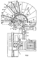
- the machining centre comprises a machine tool 1 having a working head 2, a worktable 3 and an exchanger arm 4 for the tools 40 which are mounted on the spindle 6 of the head 2.
- the head 2 shifts in the direction of the arrow 7 to bring the spindle 6 into a position S, in which the arm 4 extracts the used tool from the spindle 6 and, after a rotation of 180°, deposits a fresh tool in the spindle.
- the arm 4 then deposits the used tool 40 in a location in a magazine indicated generally by the reference 10.
- the magazine 10 for the tools is positioned beside the machine 1 and comprises a series of fixed cradles 12, each adapted to contain and guide a structure 14, hereinafter called a "pallet", for supporting the tools 40.
- the cradles 12, which are all alike, are arranged in fan or rack fashion and mutually equidistant along a circular arc which may extend up to 180°.
- Each cradle 12 constitutes a modular element or module of the magazine, for which reason the magazine 10 can be constructed by degrees, installing first of all a small number of modules 12, and then, according to needs, it can be supplemented by adding other modules 12.
- the modular elements 12 may be installed singly or in groups. Each group may comprise, for example, three interconnected modules, as indicated by the reference 20 in Fig. 1.
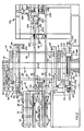
- a modular element 12 (Fig. 2) is formed by two vertical posts 22 connected by two horizontal crosspieces 24, which also serve as guides for the sliding of the respective pallet 14 and its support in a vertical position.
- Each pallet 14 (Fig. 3) is formed by two horizontal bars 26, 27 connected by two uprights 30, 31. Between the uprights 30, 31 there are disposed two crosspieces 33, 34 parallel to the bars 26, 27 and bearing wheels 36 for sliding on the guides 24.
- a handling device 45 used for selecting the pallets 14 in the magazine and for transferring the pallets 14 from the magazine 10 to the exchanger arm 4 and vice versa.
- the handling device 45 (Fig. 2) comprises a pair of discs 48 and 50 keyed on a vertical shaft 52 rotatable in a bottom base 54 and in a fixed top arm 56 fast with the base 54.
- the discs 48 and 50 are rotated through 180° in both directions by a hydraulic motor 58 by means of a pinion 59 meshing with a toothed wheel 60 keyed on the shaft 52.
- the shaft 52 of the discs 48 and 50 is positioned relative to the magazine 10 in such manner that the path of the axis of the pins 62 and 64 during the rotation of the discs 48 and 50 passes through the axis of the magazine 10 represented in Fig. 1 by the point P, at which the axes 18 of the pallets 14 meet.
- Each cage 68 or 70 comprises a vertical frame structure formed by two arms 76, 78 (Fig. 2) which are parallel and connected by uprights 79.
- Two guides 81 which are parallel and in positions corresponding to the guides 24 of the module 12 are fixed to the uprights 79 for enabling the pallet 14 to be transferred to the cage 68, as will be described hereinafter.
- the discs 48 and 50 are locked in the position shown in Fig. 1, in which the axis of one or the other of the two pairs of pins 62 and 64, for example the pins 62, 62', is aligned with the point P.
- the cage 68 is in a position C called the loading position and the cage 70 is in a position F called the exchange position.
- the two cages are interchanged.
- the cage 68 or 70 can be made to rotate on the discs 48 and 50 by means of a suitable motor 80 (Fig. 2) in the direction of the arrow 72 (Fig. 1) to position itself in front of the pallets 14 in perfect alignment with each of them, as shown in chain-dotted lines at 141.
- a suitable motor 80 Fig. 2
- Fig. 1 a suitable motor 80
- Fig. 1 a suitable motor 80
- Fig. 2 a suitable motor 80
- Fig. 1 a suitable motor 80
- Fig. 1 a suitable motor 80
- Fig. 1 a suitable motor 80
- Fig. 1 a suitable motor
- a particular recognition code for the pallets may be represented by the combination of the heights of four cams 41, 42, 43, 44 (Fig. 3) mounted on a support 45 fixed to the bar 27 of each pallet.
- the cams 41-44 are tested by as many sensors 46 (Fig. 2) mounted on a bracket 47 fixed to the upright 79 of each of the cages 68 and 70.
- the cams 41 and 43 are "high” and the cams 42 and 44 are "low", for which reason the binary code represented is 1010.
- a pallet 14 is engaged and drawn onto the cage 68 or 70 by means of a chain drawing device 74 mounted on the upper arm 76 (Fig. 2) of each of the cages 68, 70.
- the drawing device 74 (Fig. 4) comprises a chain 82 passed around two rotatable pulleys 84 and 86 at the ends of the upper arm 76 of the cages 68 and 70.
- the pulley 84 is a driving pulley and is connected to a hydraulic motor 85 fixed on the top of the arm 76, while the chain 82 is disposed below the arm 76.
- Fixed to the chain 82 is a downwardly projecting pin 88 (Fig. 2), which, during the movement of the chain 82, engages in a guide 90 (Fig. 4) at right angles to the rectilinear strands 82 a and 82 b of the chain 82.
- the guide 90 is formed in a block 92 fast with the top part of each pallet 14.
- the pallets 14 are normally held locked in the magazine 10 by a latch (not shown) which engages a hook 190 on the pallet. This latch is removed automatically or manually to release the pallet 14 from the seat 12.
- the pallets 14 are positioned in such manner that, when the pin 88 turns around the pulley 84 counterclockwise, it engages in the guide 90, which is in the position indicated in dotted lines in Fig. 4, prearranging itself for the ensuing drawing of the pallet 14 onto the guides 81 of the cage 68 or 70. After the chain 82 has transported the pin 88 until it is in correspondence with the pulley 86, along the strand 82 a , the pallet 14 is fully introduced into the cage 68.
- the pin 88 With a following movement of the chain 82 in the same direction, the pin 88 turns counterclockwise around the pulley 86, as indicated by a chain-dotted line in Fig. 4, and actuates a latch device 94 for locking the pallet 14 on the cage 68 or 70.
- the latch device 94 is contained in the block 92 (Figs. 5 and 6) fixed to the pallet by means of a right-angled bracket 93 and comprises a slide 96 slidable below the guide 90 parallel thereto.
- the slide 96 is provided with a shoulder 103 and with a stud 100 between which the pin 88 can engage.
- a spring 98 normally keeps the slide 96 shifted towards the left in Fig. 6, so as to bring the stud 100 outside the guide 90.
- This is provided with a flared portion 91 which allows the pin 88 to insert itself between the shoulder 103 and the stud 100.
- the slide 96 is kept connected to the block 102 by the spring 98 compressed between the block 92 and an abutment of the slide 96.
- the lower pin 62', 64' (Figs. 2 and 7), rotatable on the disc 50, is connected through the medium of a front coupling 110 to a shaft 112 rotatable on the base 54 and coaxial with the pin 62', 64'.
- the coupling 110 comprises a prismatic element 113 integral with the shaft 112 and slidable in a guide 114 at right angles to the pin 62', 64' and formed in a block 114' integral with the pin itself.
- the shaft 112 is fast with a pull arm 116 used to rotate the cage 68, 70 about the pin 62, 64 towards one of the positions 141 (Fig. 1) in front of the modules 12 of the magazine 10.
- the arm 116 is driven by the motor 80 (Fig. 7) by means of a pinion 120 meshing with a chain 122 passed around the outside of a guide 126 fast with the base 54.
- the guide 126 is circular and concentric with the axis of the shaft 112. Therefore, when the arm 116 (Fig. 2) is rotated about the shaft 112 by the motor 80, the cage 68, 70 is also rotated on the pins 62, 64 and 62', 64' by means of the coupling 110.
- One end 178 (Fig. 7) of the arm 78 bears on a pillar 130 fast with the arm 116 and provided with a roller 131 rolling on the guide 126 in order to unload the weight of the cage 68, 70 and the respective pallet onto the base 54.
- Two pads 132, one on the pillar and one on the end 178 are provided for facilitating superposition of the end 178 on the pillar 130.
- a hydraulic positioning device 136 (Fig. 7) which pushes a roller 138 into notches 140 distributed uniformly in the guide 126.
- the hydraulic positioning device 136 is fixed to the arm 116 and comprises a rod 142 (Fig. 8) moved axially by a plunger 144 slidable in a cylinder 145.
- the rod 142 extends into a chamber 146 filled with oil under pressure for control of the motor 80.
- the rod portion 148 inside the chamber 146 has an undercut 149 which, by moving the rod 142, opens or closes the passage between the chamber 146 and a duct 150 for feeding the motor 80.
- the rod 142 is slidable in a support 152 for the roller 138 in opposition to the action of a spring 154 which is kept compressed between a collar 156 of the rod 142 and the support 152.
- the plunger 144 is actuated by oil under pressure delivered selectively into one of the two chambers of the cylinder 145 through the ducts 155 and 157.
- the undercut 149 allows the flow of the oil towards the motor 80, which shifts the cage 68, 70 along the rack 122 (Fig. 7).
- oil under pressure is delivered into the duct 155 (Fig. 8) to shift the rod 142 downwardly.
- the duct 150 is isolated from the chamber 146 and the motor 80 therefore stops.
- the collar 156 compresses the spring 154 against the support 152 and, as soon as the roller 138 is facing a notch 140, it snaps into it, locking the cage 68, 70 in that position.
- the positioning device 136 is pivoted on two pivots 258 of an annular support 158 connected in turn to a bracket 159 borne by the arm 116 (Figs. 8, 9), and is maintained in a stable position (Fig. 8) by two spring shock absorbers 160 for deadening the recoil movements of arrest.
- the element 113 and the guide 114 are disposed perpendicularly to the line joining the axis of the shaft 52 to the point P, wherefore they are shown in Fig. 7 in section in the diametral plane.
- two identical locking devices 170 are used, only one of which is shown in Fig. 2, these devices being mounted on the top face of the disc 48.
- a rocking lever 172 (Figs. 2 and 10) is pivoted at 173 on the disc 48 and is adapted to lift a latch 174 extending through a drilled projection 176 of the disc 48.
- the lever 172 is rotated clockwise by the fixed crosspiece 56 and keeps the latch 174 raised.
- the discs 48 and 50 rotate clockwise, they carry the cage 68 or 70 along in the same direction for a certain travel by means of a pin 63 (Fig. 2) until the lever 172 (Figs. 2 and 10) is released from engagement with the crosspiece 56.
- the latch 174 is then pushed by a spring 178 into a hole 179 in the upper crosspiece 76 of the cage 68, 70, thus connecting it to the disc 48.
- the pallet 14 contained in the cage 68, 70 now in the position F in Fig. 1 is withdrawn to the right in Fig. 2 to bring the tools into the operating zone of the exchanger arm 4 by operating the chain 82 in the direction opposite to that seen hereinbefore.
- the pallet 14 is then released from the lock 102 (Figs. 4 and 5) and moved out of the cage 68, 70 along the guides 180 and 182 of an auxiliary support 184 (Figs. 1 and 2) which is fixed and aligned with the cage 68, 70 in the position F, which constitutes the tool changing station between the selected pallet 14 and the spindle 6.
- the pallet 14 is connected by means of a hook 190 (Fig. 3) with a notch 191 carried by a bar 192 (Fig. 2) slidable on the guides 180 and 182 by means of rollers 195.
- the bar 192 is provided with notches 194 inside which a roller 197 of a positioning device 186 is positioned.
- the positioning device 186 is similar to the device 136 (Fig. 8) and is used to lock the pallet 14 in the positions defined by the notches 194 corresponding to the seats 38 where the arm 4 (Fig. 1) withdraws (or deposits) a tool.
- a linear position detector 200 of known type comprising an optical or magnetic sensor 202 for detecting equidistant notches 203 along the bottom face 204 of the bar 192.
- the detector 200 connected to a conventional control circuit not shown in the drawings, enables the positioning device 186 to be actuated when a predetermined tool seat 38 of the pallet 14 is in correspondence with the exchanger arm 4 (Fig. 1).
- the chain 82 serves both to withdraw the pallet 14 from the magazine 10 and insert it therein, and to position the pallet 14 selectively so as to bring the tool into correspondence with the exchanger arm 4.
- the motor 85 is therefore operated for a prefixed travel or distance controlled by the switches 69 and 89 in the first case and through the agency of the position detector 200 in the second case.
- the vertical arrangement of the pallets 14 in the magazine 10 and the rack configuration of the magazine itself enable the area required for the machining centre to be considerably reduced. Moreover, the pallets 14 can be easily transported even in small spaces.
- the pallets 14 are loaded with the tools in a suitable room for distributing the tools, called the "tool room", and from here are transported manually, or by automatically guided trolleys, to be inserted in the magazine 10 from the outside E (Fig. 1). Moreover, at any moment and without impeding the machining operations in progress, the pallets contained in the magazine 10 can be withdrawn from the outside E after releasing the hook 190 and be transported manually or automatically with wire-guided trolleys to the magazines of other machining centres.
- Recognition of the pallets 14 is achieved with suitable identification codes obtained by means of cams 206 (Fig. 3) read by a suitable reader carried by the trolley and which are similar to the cams 41-44 previously described and fixed to each pallet 14 on the upright 30 facing towards the outside of the magazine.
- the handling device 45 may contain four cages disposed on the discs 48 and 50 at 90° one from the other.
- this device can translate on suitable guides not shown in the drawings to move away from the magazine 10 into a position suitable for also serving a second machining centre.
Landscapes
- Engineering & Computer Science (AREA)
- Mechanical Engineering (AREA)
- Automatic Tool Replacement In Machine Tools (AREA)
Claims (19)
- Bearbeitungszentrum mit einem Magazin für Werkzeuge, wobei das Magazin mehrere Werkzeugträger (14) zum Tragen einer Gruppe von Bearbeitungswerkzeugen (40) und mehrere feststehenden Gestelle zur entnehmbaren Aufnahme der Werkzeugträger aufweist, das Zentrum eine Werkzeugwechselvorrichtung (4) aufweist, die zwischen einer Werkzeugwechselstation (F) und einer Bearbeitungsmaschine (2) angeordnet ist, und das Magazin eine Handhabungsvorrichtung (45) aufweist, die in der Lage ist, einen ersten Werkzeugträger, der aus dem Magazin entnommen wurde, gegen einen zweiten Werkzeugträger auszutauschen, der in der Werkzeugwechselstation (F) angeordnet ist,
dadurch gekennzeichnet, daß die Handhabungsvorrichtung aufweist: zwei Scheiben (48, 50), die auf eine vertikale, auf einer Basis (54) drehbare Welle (52) aufgekeilt sind, wenigstens zwei symmetrische Rahmen (68, 70), die jeweils auf zwei Zapfen (62, 62'; 64, 64'), die auf den Scheiben an sich diametral gegenüberliegenden Stellen gelagert sind, schwenkbar sind und in der Lage sind, die Werkzeugträger vertikal zu tragen, und Drehmittel zum Drehen der vertikalen Welle (62) um 180°, um gleichzeitig die Rahmen (68, 70), die jeweils den ersten und zweiten Werkzeugträger tragen, von einer Ladestation (C), die mit irgendeinem der Gestelle fluchtet, zur Wechselstation (F) in der Nähe der Werkzeugwechselvorrichtung zu transferieren, so daß der erste Werkzeugträger von dem entsprechenden Rahmen zur Wechselstation bewegt wird, während der zweite Werkzeugträger gleichzeitig von dem entsprechenden Rahmen zum Magazin bewegt wird;
in dem die Gestelle längsseits zueinander in Form eines Flügelrades längs eines offenen Kreisbogens angeordnet sind, der neben der Bearbeitungsmaschine liegt und einen Mittelpunkt (P) aufweist, wobei die vertikale Welle (52) so in bezug auf den Kreisbogen positioniert ist, daß die Achse der Zapfen (62, 64) durch den Mittelpunkt (P) des Kreisbogens verläuft, wenn der eine oder andere Rahmen (68, 70) in der Ladestation (C) angeordnet ist;
und in dem jeder Rahmen (68, 70) einen Transfermechanismus (74) aufweist, der mit den Werkzeugträgern (14) zusammenwirkt, um diese Träger von den Gestellen (12) zu dem einen oder anderen Rahmen zu transferieren, wenn er in der Ladestation (C) angeordnet ist, und um die Werkzeugträger relativ zu der Werkzeugwechselvorrichtung (4) zu positionieren, wenn der eine oder andere Rahmen in der Werkzeugwechselstation angeordnet ist. - Bearbeitungszentrum nach Anspruch 1,
dadurch gekennzeichnet,
daß eine Transfervorrichtung (74) auf jedem der Rahmen angebracht ist, die so betätigt wird, daß sie wählbar den ersten Werkzeugträger aus dem Magazin zum ersten Rahmen (68) in der Ladestation (C) und den zweiten Werkzeugträger aus der Wechselstation zum zweiten Rahmen (70) bewegt, und umgekehrt. - Bearbeitungszentrum nach Anspruch 1 oder 2,
gekennzeichnet durch
einen Positioniermechanismus, der wählbar mit einem der Rahmen in der Ladestation (C) verbindbar ist, um den Rahmen um die Zapfen zu drehen und vor ein ausgewähltes der Gestelle (12) zu positionieren, so daß ein entsprechender Werkzeugträger, der in dem ausgewählten Gestell aufgenommen ist, aus dem Magazin in den Rahmen geladen wird, und umgekehrt. - Bearbeitungszentrum nach Anspruch 1, 2 oder 3,
dadurch gekennzeichnet,
daß die Rahmen (68, 70) während der erwähnten Drehung wählbar auf den Scheiben (48, 50) verriegelt werden, und zwar mittels eines Verriegelungsmechanismus (170), der auf einer der Scheiben angebracht und durch ein an der Basis (54) befestigtes Element (56) gesteuert wird, wobei dieser Mechanismus aufweist: ein bewegliches Teil (170), das in der Lage ist, die Rahmen mit der Scheibe zu verbinden, und einen Hebel (172), der mit dem beweglichen Teil verbunden ist und durch das fest mit der Basis verbundene Element gedreht wird, um einen der Rahmen in der Ladeposition (C) freizugeben. - Bearbeitungszentrum nach Anspruch 1, 2 oder 3,
dadurch gekennzeichnet,
daß die Rahmen (68, 70) während der erwähnten Drehung wählbar an den Scheiben (48, 50) mittels eines Verriegelungsmechanismus (170) verriegelt werden, der an einer der Scheiben angebracht ist und durch ein mit der Basis (54) fest verbundenes Element (56) gesteuert wird, wobei dieser Mechanismus aufweist: ein bewegliches Teil (170), das in der Lage ist, die Scheibe mit den Rahmen zu verbinden, und eine Steuerkurve, die an dem fest mit der Basis verbundenen Element angebracht ist und mit dem beweglichen Teil zusammenwirkt, um einen der Rahmen in der Ladeposition (C) freizugeben. - Bearbeitungszentrum nach einem der Ansprüche 1 bis 5,
dadurch gekennzeichnet,
daß die vertikale Welle (52) durch einen reversierbaren Motor (58) angetrieben wird, der mit einem fest mit der Welle verbundenen Zahnkranz (60) in Eingriff steht. - Bearbeitungszentrum nach einem der Ansprüche 1 bis 6,
dadurch gekennzeichnet,
daß die feststehenden Gestelle (12) und die Rahmen (68, 70) jeweils Gleitführungen (24, 81) für die Werkzeugträger (14) aufweisen, wobei die Führungen miteinander fluchten, wenn sich einer der Rahmen in der Ladeposition (C) zum Transferieren des Werkzeugträgers vom Gestell zum Rahmen befindet. - Bearbeitungszentrum nach einem der Ansprüche 1 bis 7,
dadurch gekennzeichnet,
daß der Transfermechanismus (74) eine Kette (82) aufweist, die um zwei an den Rahmen (68, 70) drehbar gelagerten Rädern (84, 86) herumläuft und ein Verbindungselement (88) trägt, das wählbar mit einem Mitnahmeglied (90) zusammenwirkt, das fest mit jedem der Werkzeugträger (14) verbunden ist. - Bearbeitungszentrum nach Anspruch 8,
dadurch gekennzeichnet,
daß das Verbindungselement (88) einen an der Kette (82) überhängend befestigten Zapfen und das Mitnahmeglied einen Block (92) mit einer Nut (90) aufweist, die sich senkrecht zur Bewegungsrichtung der Kette erstreckt und den Zapfen aufnehmen kann, so daß der Zapfen nur dann in die Nut eingreift, wenn er längs des einen Trums der Kette bewegt wird. - Bearbeitungszentrum nach Anspruch 8 oder 9,
dadurch gekennzeichnet,
daß das Mitnahmeglied (92) eine Verrastungsvorrichtung (94) aufweist, die mit den betreffenden Rahmen (68, 70) zusammenwirkt, um den Werkzeugträger (14) fest mit dem Rahmen zu verbinden, nachdem der werkzeugträger zum Rahmen transferiert worden ist. - Bearbeitungszentrum nach Anspruch 10,
dadurch gekennzeichnet,
daß die Verrastungsvorrichtung (94) einen Schieber (96) aufweist, der in dem Block (92) gleitend verschiebbar ist und durch den Zapfen (88) bewegt wird, wobei der Schieber mit einer Verriegelung (101, 102) zusammenwirkt, die fest mit jedem der Rahmen (68, 70) verbunden ist, wenn der Werkzeugträger (14) sich auf dem Rahmen befindet. - Bearbeitungszentrum nach einem der Ansprüche 1 bis 11,
dadurch gekennzeichnet,
daß die Handhabungsvorrichtung (45) einen Zugarm (116) aufweist, der wählbar mit dem einen oder anderen der Rahmen (68, 70) in der Ladeposition (C) verbindbar ist, um den Rahmen auf den Zapfen (62, 64) längs des Kreisbogens in eine Lage zu bringen, in der er mit einem der Gestelle (12) fluchtet. - Bearbeitungszentrum nach Anspruch 12,
dadurch gekennzeichnet,
daß der Zugarm (116) fest mit einer Welle (112) verbunden ist, die auf der Basis (54) drehbar und koaxial mit einem der Zapfen (62, 64) ist, wenn sich die Scheiben (48, 50) in der Ladeposition (C) befinden, wobei die Welle an ihrem Ende ein prismatisches Element (113) trägt, das in eine entsprechende Nut (114) in dem Zapfen einführbar ist, um den Zugarm mit dem Rahmen zu verbinden. - Bearbeitungszentrum nach Anspruch 12 oder 13,
dadurch gekennzeichnet,
daß das Ende des Zugarms (116), das der Welle (112) gegenüberliegt, mit einem Element (122) verbunden ist, das auf einer feststehenden kreisförmigen Führung (126) gleitend verschiebbar ist, die mit dem Kreisbogen konzentrisch ist. - Bearbeitungszentrum nach Anspruch 14,
dadurch gekennzeichnet,
daß der Zugarm (116) durch einen reversierbaren Motor (80) drehbar ist, der in dem Arm befestigt ist und ein Ritzel (120) dreht, das mit einem Umlaufgetriebe (Kette 122) in Eingriff steht, das mit der kreisförmigen Führung (126) fest verbunden ist. - Bearbeitungszentrum nach Anspruch 14 oder 15,
dadurch gekennzeichnet,
daß eine erste Positioniervorrichtung (136), die mit dem Zugarm (116) fest verbunden ist, in der Lage ist, den Arm in der ausgewählten Lage mittels eines Verriegelungselements (142) zu verriegeln, das durch die erste Positioniervorrichtung in Sitze (146) in der kreisförmigen Führung (126) eingeführt ist. - Bearbeitungszentrum nach einem der Ansprüche 1 bis 16,
gekennzeichnet durch
einen weiteren feststehenden Rahmen (184), der mit dem ersten oder zweiten Rahmen (68, 70) in der Transferposition (F) fluchtet, um den Werkzeugträger (14) während des Werkzeugwechsels mit der Werkzeugwechselvorrichtung (4) zu führen und zu tragen. - Bearbeitungszentrum nach Anspruch 17,
dadurch gekennzeichnet,
daß der dritte Rahmen (184) eine gleitend verschiebbare Positionierstange (192) aufweist, die mit mehreren Ausschnitten (194) versehen und mit dem Werkzeugträger (14) verbindbar ist, um ihn in vorbestimmten Wechselpositionen in bezug auf die Werkzeugwechselvorrichtung zu arretieren. - Bearbeitungszentrum nach Anspruch 17 oder 18,
dadurch gekennzeichnet,
daß der dritte Rahmen (184) eine zweite Positioniervorrichtung (186) aufweist, die mit einem bewegbaren Anschlagglied (197) versehen ist, der in einen der Ausschnitte (194) in Übereinstimmung mit den Wechselpositionen einführbar ist.
Applications Claiming Priority (2)
| Application Number | Priority Date | Filing Date | Title |
|---|---|---|---|
| IT8667755A IT1215192B (it) | 1986-10-06 | 1986-10-06 | Centro di lavorazione con magazzino per gli utensili |
| IT6775586 | 1986-10-06 |
Publications (3)
| Publication Number | Publication Date |
|---|---|
| EP0263682A2 EP0263682A2 (de) | 1988-04-13 |
| EP0263682A3 EP0263682A3 (en) | 1989-07-05 |
| EP0263682B1 true EP0263682B1 (de) | 1992-07-29 |
Family
ID=11305040
Family Applications (1)
| Application Number | Title | Priority Date | Filing Date |
|---|---|---|---|
| EP87308857A Expired - Lifetime EP0263682B1 (de) | 1986-10-06 | 1987-10-06 | Bearbeitungszentrum mit Werkzeugspeicher |
Country Status (4)
| Country | Link |
|---|---|
| US (1) | US4800645A (de) |
| EP (1) | EP0263682B1 (de) |
| DE (1) | DE3780745D1 (de) |
| IT (1) | IT1215192B (de) |
Families Citing this family (4)
| Publication number | Priority date | Publication date | Assignee | Title |
|---|---|---|---|---|
| JPS63229240A (ja) * | 1987-03-17 | 1988-09-26 | Kitamura Mach Co Ltd | パレツトチエンジヤ |
| US5613930A (en) * | 1995-06-30 | 1997-03-25 | Lucent Technologies, Inc. | Device for extracting, storing and handling drill bit cassettes |
| DE502004005012D1 (de) * | 2003-12-22 | 2007-10-31 | Komax Holding Ag | Kabelbearbeitungseinrichtung |
| KR100579085B1 (ko) * | 2003-12-27 | 2006-05-12 | 두산인프라코어 주식회사 | 자동공구교환장치의 공구매거진 이송장치 |
Family Cites Families (9)
| Publication number | Priority date | Publication date | Assignee | Title |
|---|---|---|---|---|
| US3691655A (en) * | 1970-01-15 | 1972-09-19 | Toyoda Machine Works Ltd | Machine tool with tool change device |
| US4240194A (en) * | 1976-04-09 | 1980-12-23 | Sumiaki Inami | Automatic tooling machine |
| CH602454A5 (de) * | 1977-01-17 | 1978-07-31 | Oerlikon Buehrle Ag | |
| CH621991A5 (de) * | 1977-09-14 | 1981-03-13 | Oerlikon Buehrle Ag | |
| DE2811357A1 (de) * | 1978-03-16 | 1979-09-27 | Norbert Ing Grad Ewertowski | Einrichtung zum automatischen werkzeugwechsel an mehrspindelbohrmaschinen |
| US4590662A (en) * | 1982-09-03 | 1986-05-27 | Makino Milling Machine Co., Ltd. | Tool changing machine of machine tool |
| DE3320762C2 (de) * | 1983-06-09 | 1994-10-27 | Trumpf Gmbh & Co | Stanzmaschine mit einem stationären Magazin |
| BG38822A1 (en) * | 1983-11-03 | 1986-03-14 | Stoilov | Cutting machine with automatic exchange of tools magazines |
| US4654957A (en) * | 1984-06-22 | 1987-04-07 | Ex-Cell-O Corporation | Flexible machining apparatus with single shank tool and multi-spindle tool head changing and operating capabilities |
-
1986
- 1986-10-06 IT IT8667755A patent/IT1215192B/it active
-
1987
- 1987-10-05 US US07/104,082 patent/US4800645A/en not_active Expired - Fee Related
- 1987-10-06 EP EP87308857A patent/EP0263682B1/de not_active Expired - Lifetime
- 1987-10-06 DE DE8787308857T patent/DE3780745D1/de not_active Expired - Lifetime
Also Published As
| Publication number | Publication date |
|---|---|
| US4800645A (en) | 1989-01-31 |
| IT8667755A0 (it) | 1986-10-06 |
| EP0263682A3 (en) | 1989-07-05 |
| IT1215192B (it) | 1990-01-31 |
| DE3780745D1 (de) | 1992-09-03 |
| EP0263682A2 (de) | 1988-04-13 |
Similar Documents
| Publication | Publication Date | Title |
|---|---|---|
| US4306350A (en) | Automatic tool changer and tool storage arrangement for machine tool | |
| JP3337714B2 (ja) | マガジン | |
| EP0806998B1 (de) | Werkzeugmaschine mit horizontalen spindeln | |
| US3161951A (en) | Automatic tool handling apparatus | |
| EP0356216B1 (de) | Automatischer Palettenwechsler | |
| US3817391A (en) | Tool storage magazine | |
| US3256600A (en) | Tool changing mechanism | |
| CA2070102C (en) | Manufacturing plant | |
| GB1584079A (en) | Method and apparatus for automatically changing tool heads | |
| CN87101752A (zh) | 机床装刀用刀具载送器 | |
| US4221043A (en) | Automatic tool changer for multiple spindle machine tool | |
| US4995502A (en) | Pallet changer | |
| US4190947A (en) | Automatic tool exchanging apparatus of machine tool | |
| EP4159365B1 (de) | Werkzeugmagazin für einen automatischen werkzeugwechsler | |
| EP0263682B1 (de) | Bearbeitungszentrum mit Werkzeugspeicher | |
| US4654957A (en) | Flexible machining apparatus with single shank tool and multi-spindle tool head changing and operating capabilities | |
| US4288909A (en) | Automatic tool changer for machine tool | |
| KR20020069107A (ko) | 물품취급설비 | |
| JP7369722B2 (ja) | 工作機械のためにパレットを保管及び輸送するパレットシステム | |
| US3591920A (en) | Tool change mechanism with magazine positioning means | |
| JP7461820B2 (ja) | ワークテーブル | |
| JPH0698546B2 (ja) | 主に切削加工に使用可能な工作機械 | |
| US5453068A (en) | Machine tool | |
| US6102839A (en) | Tool-change system for a machine tool with a number of machining heads | |
| CN224011262U (zh) | 立式车床的卡盘更换装置 |
Legal Events
| Date | Code | Title | Description |
|---|---|---|---|
| PUAI | Public reference made under article 153(3) epc to a published international application that has entered the european phase |
Free format text: ORIGINAL CODE: 0009012 |
|
| AK | Designated contracting states |
Kind code of ref document: A2 Designated state(s): CH DE FR GB LI |
|
| PUAL | Search report despatched |
Free format text: ORIGINAL CODE: 0009013 |
|
| AK | Designated contracting states |
Kind code of ref document: A3 Designated state(s): CH DE FR GB LI |
|
| 17P | Request for examination filed |
Effective date: 19891220 |
|
| 17Q | First examination report despatched |
Effective date: 19910110 |
|
| RAP1 | Party data changed (applicant data changed or rights of an application transferred) |
Owner name: OCN-PPL S.P.A. |
|
| GRAA | (expected) grant |
Free format text: ORIGINAL CODE: 0009210 |
|
| AK | Designated contracting states |
Kind code of ref document: B1 Designated state(s): CH DE FR GB LI |
|
| PG25 | Lapsed in a contracting state [announced via postgrant information from national office to epo] |
Ref country code: LI Effective date: 19920729 Ref country code: FR Effective date: 19920729 Ref country code: DE Effective date: 19920729 Ref country code: CH Effective date: 19920729 |
|
| REF | Corresponds to: |
Ref document number: 3780745 Country of ref document: DE Date of ref document: 19920903 |
|
| PG25 | Lapsed in a contracting state [announced via postgrant information from national office to epo] |
Ref country code: GB Effective date: 19921029 |
|
| REG | Reference to a national code |
Ref country code: CH Ref legal event code: PL |
|
| EN | Fr: translation not filed | ||
| PLBE | No opposition filed within time limit |
Free format text: ORIGINAL CODE: 0009261 |
|
| STAA | Information on the status of an ep patent application or granted ep patent |
Free format text: STATUS: NO OPPOSITION FILED WITHIN TIME LIMIT |
|
| GBPC | Gb: european patent ceased through non-payment of renewal fee |
Effective date: 19921029 |
|
| 26N | No opposition filed |