EP0263768B1 - Palette articulée pour dispositif d'épandage - Google Patents
Palette articulée pour dispositif d'épandage Download PDFInfo
- Publication number
- EP0263768B1 EP0263768B1 EP87440049A EP87440049A EP0263768B1 EP 0263768 B1 EP0263768 B1 EP 0263768B1 EP 87440049 A EP87440049 A EP 87440049A EP 87440049 A EP87440049 A EP 87440049A EP 0263768 B1 EP0263768 B1 EP 0263768B1
- Authority
- EP
- European Patent Office
- Prior art keywords
- axis
- stirrup
- pallets
- rotation
- beater
- Prior art date
- Legal status (The legal status is an assumption and is not a legal conclusion. Google has not performed a legal analysis and makes no representation as to the accuracy of the status listed.)
- Expired - Lifetime
Links
- 238000003466 welding Methods 0.000 claims description 7
- 239000000047 product Substances 0.000 description 8
- 230000005540 biological transmission Effects 0.000 description 2
- 210000003608 fece Anatomy 0.000 description 2
- 239000007788 liquid Substances 0.000 description 2
- 235000008733 Citrus aurantifolia Nutrition 0.000 description 1
- 229910000746 Structural steel Inorganic materials 0.000 description 1
- 235000011941 Tilia x europaea Nutrition 0.000 description 1
- 230000007797 corrosion Effects 0.000 description 1
- 238000005260 corrosion Methods 0.000 description 1
- 230000000694 effects Effects 0.000 description 1
- 239000004571 lime Substances 0.000 description 1
- 239000012263 liquid product Substances 0.000 description 1
- 239000010871 livestock manure Substances 0.000 description 1
- 210000000056 organ Anatomy 0.000 description 1
- 230000000750 progressive effect Effects 0.000 description 1
- 239000010802 sludge Substances 0.000 description 1
Images
Classifications
-
- A—HUMAN NECESSITIES
- A01—AGRICULTURE; FORESTRY; ANIMAL HUSBANDRY; HUNTING; TRAPPING; FISHING
- A01C—PLANTING; SOWING; FERTILISING
- A01C17/00—Fertilisers or seeders with centrifugal wheels
- A01C17/001—Centrifugal throwing devices with a vertical axis
Definitions
- the present invention relates to the field of spreading devices, and relates to an articulated pallet intended to be mounted on the upper face of the projection table of such a device.
- the spreading devices are intended for spreading various products, such as manure, droppings of dry or semi-liquid hens, sludge from treatment plants, dry or semi-liquid, industrial residues, such as scum sugar or lime, or more generally any powdery product.
- These devices are composed of two stages and are mounted at the rear of a conventional trailer, a watertight door with hydraulic opening, mounted in the trailer body allowing the transport of semi-liquid products.
- the progressive opening of the door allows the product to be channeled to the two-stage spreading device.
- the upper floor is made up of two detanglers with horizontal and parallel axes which crumble the product inside a box, the rear wall of which can be lifted. The crumbled product falls on a spreading table which constitutes the lower floor.
- the table is flat and tilted, preferably 12 ° upwards at the back.
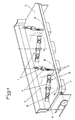
- On the upper face of this table can be mounted, for example, four distribution pallets for wide spreading devices (from eight to twelve meters). These four pallets are mounted in line, the axis of rotation being perpendicular to the surface of the table. The length of the pallets is greater than the distance between them and the mounting on their axis is such that they cannot collide. Their direction of rotation is reversed from one to the other. The front part of the table is folded upwards and the end of the pallets pass approximately two centimeters from this face.
- the pallets being rigid over their entire length, the risks of blockage are numerous.
- the product to be spread contains foreign bodies, such as stones, these cause a blockage, at the level of the passage of about two centimeters between the pallets and the front part of the table, which causes twists on the shaft ends of the bevel gear drives the pallets.
- the resistance torque opposed to the pallets being very high, it absorbs power and creates very strong stresses on the organs of transmission.
- the subject of the present invention is, in fact, a distribution pallet adapted to be mounted on the upper face of a projection table constituting the lower stage of a spreading device and having at each of its two longitudinal ends a articulated plate, pallet characterized in that it is composed of two angles, fixed in a known manner, for example by welding, on an axis of rotation, each plate being connected to the end of each angle, by means of articulation, such that each articulation axis is parallel to the axis of rotation of the pallets and in that the articulation means is in the form of three elements, one of which is in contact with the two others, so that this means has only two points of contact between the three elements.
- the pallet 1 has at each of its two longitudinal ends an articulated plate 3.
- FIG. 1 it is composed of two angles 4, fixed in a known manner, for example by welding, on an axis of rotation 5, each plate 3 being connected to the end of each of the angles 4, through a means articulation 6, so that each articulation axis 12 is parallel to the axis of rotation of the pallets 1.
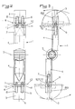
- the articulation means 6 is in the form of three elements 7, 8 and 9, one of which 7 is in contact with the other two 8 and 9, so that this means 6 has only two contact points 10 and 11 between the three elements 7, 8 and 9 ( Figure 2).
- friction is reduced to a minimum and the resistance during clogging or corrosion is reduced, which is essential, the pallets 1 working in an ambient environment, sometimes wet, sometimes sticky, sometimes aggressive.
- Each element 7, 8 and 9 may advantageously be in the form of a stirrup.
- the stirrup 7 is fixed to the angle iron 4 in a known manner, for example by welding, in a vertical plane along a longitudinal axis of the stirrup 7, the stirrups 8 and 9 being fixed, for their part, to the articulated plate 3 in known manner, for example by welding, each in a horizontal plane along a longitudinal axis of the stirrup 7, and one 8 above the frame 9 ( Figures 2 and 3).
- the two stirrups 8 and 9 and therefore the plate 3 are thus held on the pallet 1 thanks to the stirrup 7 and the plate 3 can, therefore, rotate through an angle of 180 ° along an axis of articulation. vertical 12.
- a plate 3 movable around a vertical articulation axis 12 parallel to the axis of rotation of the pallet 1.
- the articulated plates 3 extend under the effect of centrifugal force and give the pallet 1 a full length, the plates 3 can however be retracted by rotation around of the hinge pin 12 in the event of resistance of an obstacle, such as a pebble or a foreign body ature trapped at the passage level of about two centimeters between pallet 1 and the front of the table.
- an obstacle such as a pebble or a foreign body ature trapped at the passage level of about two centimeters between pallet 1 and the front of the table.
Landscapes
- Life Sciences & Earth Sciences (AREA)
- Soil Sciences (AREA)
- Environmental Sciences (AREA)
- Pallets (AREA)
- Catching Or Destruction (AREA)
- Coating Apparatus (AREA)
- Sheets, Magazines, And Separation Thereof (AREA)
Description
- La présente invention concerne le domaine des dispositifs d'épandage, et a pour objet une palette articulée destinée à être montée sur la face supérieure de la table de projection d'un tel dispositif.
- Les dispositifs d'épandage sont destinés à épandre des produits divers, tels que du fumier, des fientes de poules sèches ou semi-liquides, des boues de station d'épuration, sèches ou semi-liquides, des résidus industriels, tels que écumes de sucrerie ou chaux, ou plus généralement tous produits pulvérulents. Ces dispositifs sont composés de deux étages et se montent à l'arrière d'une remorque classique, une porte étanche à ouverture par commande hydraulique, montée dans la caisse de la remorque permettant le transport des produits semi-liquides. L'ouverture progressive de la porte permet la canalisation du produit vers le dispositif d'épandage à deux étages. L'étage supérieur est constitué de deux démêleurs à axes horizontaux et parllèles qui émiettent le produit à l'intérieur d'un caisson dont la paroi arrière est relevable. Le produit émietté tombe sur une table d'épandage qui constitue l'étage inférieur. La table est plane et inclinée, de préférence de 12° vers le haut à l'arrière. Sur la face supérieure de cette table peuvent être montées, par exemple, quatre palettes de distribution pour les dispositifs d'épandage de grande largeur (de huit à douze mètres). Ces quatre palettes sont montées en ligne, l'axe de rotation étant perpendicularie à la surface de la table. La longueur des palettes est supérieure à l'entraxe de celles-ci et le montage sur leur axe est tel qu'elles ne peuvent venir en collision. Leur sens de rotation est inversé de l'une à l'autre. La partie frontale de la table est repliée vers le haut et le passage de l'extrémité des palettes s'effectue à environ deux centimètres de cette face.
- Actuellement donc, les palettes étant rigides sur toute leur longueur, les risques de blocage sont nombreux. Par exemple, lorsque le produit à épandre contient des corps étrangers, tels que des cailloux, ceux-ci provoquent un blocage, au niveau du passage d'environ deux centimètres entre les palettes et la partie frontale de la table, ce qui entraîne des vrillages sur les embouts d'arbre des renvois d'angle commandant les palettes. En outre, lorsque les palettes sont mises en rotation, alors que les produits à épandre sont déjà sur la table d'épandage, le couple résistant opposé aux palettes étant très élevé, il absorbe la puissance et crée de très fortes contraintes sur les organes de transmission.
- On connaît également, par US-A-3 136 556, un dispositif de distribution vers l'arrière de la remorque qui présente un axe horizontal à double fléaux réalisant un épandage d'une largeur sensiblement égale à celle du plateau de la remorque.
- La présente invention a, en effet, pour objet une palette de distribution adaptée à être montée sur la face supérieure d'une table de projection constituant l'étage inférieur d'un dispositif d'épandage et présentant à chacune de ses deux extrémités longitudinales une plaque articulée, palette caractérisée en ce qu'elle est composée de deux cornières, fixées de manière connue, par exemple par soudage, sur un axe de rotation, chaque plaque étant reliée à l'extrémité de chacune des cornières, grâce à un moyen d'articulation, de telle manière que chaque axe d'articulation soit parallèle à l'axe de rotation des palettes et en ce que le moyen d'articulation est sous la forme de trois éléments dont l'un d'entre eux est au contact des deux autres, de telle sorte que ce moyen ne comporte que deux points de contact entre les trois éléments.
- L'invention sera mieux comprise grâce à la description ci-après, qui se rapporte à un mode de réalisation préféré, donné à titre d'exemple non limitatif, et expliqué avec référence aux dessins schématiques annexés, dans lesquels :
- la figure 1 est une vue en perspective d'une table d'épandage munie de palettes conforme à l'invention ;
- la figure 2 est une vue en élévation d'une palette conforme à l'invention, et
- la figure 3 est une vue en plan d'une palette conforme à l'invention.
- Conformément à l'invention, la palette 1 présente à chacune de ses deux extrémités longitudinales une plaque articulée 3.
- Comme on peut le voir sur la figure 1, elle est composée de deux cornières 4, fixée de manière connue, par exemple par soudage, sur un axe de rotation 5, chaque plaque 3 étant reliée à l'extrémité de chacune des cornières 4, grâce à un moyen d'articulation 6, de telle manière que chaque axe d'articulation 12 soit parallèle à l'axe de rotation des palettes 1.
- Selon une caractéristique de l'invention, le moyen d'articulation 6 est sous la forme de trois éléments 7, 8 et 9, dont l'un d'entre eux 7 est au contact des deux autres 8 et 9, de telle sorte que ce moyen 6 ne comporte que deux points de contact 10 et 11 entre les trois éléments 7, 8 et 9 (figure 2). Ainsi, les frottements sont réduits au minimum et la résistance lors de colmatage ou corrosion est diminuée, ce qui est primordial, les palettes 1 travaillant dans un milieu ambiant, tantôt humide, tantôt collant, tantôt agressif.
- Chaque élément 7, 8 et 9 pourra être avantageusement sous la forme d'un étrier. L'étrier 7 est fixé à la cornière 4 de manière connue, par exemple par soudage, dans un plan vertical selon un axe longitudinal de l'étrier 7, les étriers 8 et 9 étant fixés, quant à eux, à la plaque articulée 3 de manière connue, par exemple par soudage, chacun dans un plan horizontal selon un axe longitudinal de l'étrier 7, et l'un 8 au-dessus de l'ature 9 (figures 2 et 3). Les deux étriers 8 et 9 et donc la plaque 3 sont ainsi maintenus à la palette 1 grâce à l'étrier 7 et la plaque 3 peut, de ce fait, effectuer une rotation d'un angle de 180° suivant un axe d'articulation vertical 12.
- A chacune des deux extrémités d'une palette 1 se trouve, par conséquent, une plaque 3 mobile autour d'un axe d'articulation vertical 12 parllèle à l'axe de rotation de la palette 1. Ainsi, lors du démarrage, lorsque les palettes 1 sont entraînées en rotation sur une table d'épandage déjà bien remplie de produit, la face active des palettes 1 est moindre, le couple résistant opposé aux palettes 1 est peu élevé et les contraintes sont moindres sur les organes de transmission. De plus, lorsque les palettes ont atteint la vitesse de rotation choisie, les plaques articulées 3 s'étendent sous l'effet de la force centrifuge et confèrent à la palette 1 une longueur complète, les plaques 3 pouvant toutefois s'escamoter par rotation autour de l'axe d'articulation 12 en cas de résistance d'un obstacle, tel qu'un caillou ou un ature corps étranger coincé au niveau de passage d'environ deux centimètres entre la palette 1 et la partie frontale de la table.
- Bien entendu, l'invention n'est pas limitée au mode de réalisation décrit et représenté aux dessins annexés.
Claims (3)
- Palette de distribution (1) adaptée à être montée sur la face supérieure d'une table de projection (2) constituant l'étage inférieur d'un dispositif d'épandage et présentant à chacune de ses deux extrémités longitudinales une plaque articulée (3), palette caractérisée en ce qu'elle est composée de deux cornières (4), fixées de manière connue, par exemple par soudage, sur un axe de rotation (5), chaque plaque (3) étant reliée a l'extrémité de chacune des cornières (4), grâce à un moyen d'articulation (6), de telle manière que chaque axe d'articulation (12) soit parallèle à l'axe de rotation des palettes (1) et en ce que le moyen d'articulation (6) est sous la forme de trois éléments (7, 8 et 9) dont l'un d'entre eux (7) est au contact des deux autres (8 et 9), de telle sorte que ce moyen (6) ne comporte que deux points de contact (10 et 11) entre les trois éléments (7, 8 et 9).
- Palette, selon la revendication 1, caractérisée en ce que chaque élément (7, 8 et 9) est sous la forme d'un étrier.
- Palette, selon la revendication 2, caractérisée en ce que l'étrier (7) est fixé à la cornière (4) de manière connue, par exemple par soudage, dans un plan vertical selon un axe longitudinal de l'étrier (7), les étriers (8 et 9) étant fixés, quant à eux, à la plaque articulée (3) de manière connue, par exemple par soudage, chacun dans un plan horizontal selon un axe longitudinal de l'étrier (7), et l'un (8) au-dessus de l'autre (9).
Priority Applications (1)
| Application Number | Priority Date | Filing Date | Title |
|---|---|---|---|
| AT87440049T ATE78128T1 (de) | 1986-09-03 | 1987-07-31 | Schlegel fuer streuer. |
Applications Claiming Priority (2)
| Application Number | Priority Date | Filing Date | Title |
|---|---|---|---|
| FR8612459A FR2603155B1 (fr) | 1986-09-03 | 1986-09-03 | Palette articulee pour dispositif d'epandage |
| FR8612459 | 1986-09-03 |
Publications (2)
| Publication Number | Publication Date |
|---|---|
| EP0263768A1 EP0263768A1 (fr) | 1988-04-13 |
| EP0263768B1 true EP0263768B1 (fr) | 1992-07-15 |
Family
ID=9338713
Family Applications (1)
| Application Number | Title | Priority Date | Filing Date |
|---|---|---|---|
| EP87440049A Expired - Lifetime EP0263768B1 (fr) | 1986-09-03 | 1987-07-31 | Palette articulée pour dispositif d'épandage |
Country Status (4)
| Country | Link |
|---|---|
| EP (1) | EP0263768B1 (fr) |
| AT (1) | ATE78128T1 (fr) |
| DE (1) | DE3780397T2 (fr) |
| FR (1) | FR2603155B1 (fr) |
Families Citing this family (3)
| Publication number | Priority date | Publication date | Assignee | Title |
|---|---|---|---|---|
| DE4003945C2 (de) * | 1990-02-09 | 1998-08-20 | Amazonen Werke Dreyer H | Schleuderdüngerstreuer |
| DE29704938U1 (de) * | 1997-03-18 | 1998-08-20 | Maschinenfabrik Kemper GmbH, 48703 Stadtlohn | Vorrichtung zum Streuen von Stalldung o.dgl. Streugut |
| RU2287252C1 (ru) * | 2005-04-28 | 2006-11-20 | Федеральное государственное образовательное учреждение высшего профессионального образования "Азово-Черноморская государственная агроинженерная академия" (ФГОУ ВПО АЧГАА) | Рабочий орган к разбрасывателю органических удобрений из куч |
Family Cites Families (4)
| Publication number | Priority date | Publication date | Assignee | Title |
|---|---|---|---|---|
| GB655977A (en) * | 1941-02-24 | 1951-08-08 | Clifford Earl Butler | Improvements in and relating to distributors for fertilisers |
| US3136556A (en) * | 1959-01-14 | 1964-06-09 | Deere & Co | Material unloader with flail beater and hood |
| US3211461A (en) * | 1963-08-16 | 1965-10-12 | Hawk Bilt Mfg Corp | Material unloader |
| DE2444087A1 (de) * | 1974-09-14 | 1976-03-25 | Ernst Weichel | Streuwagen |
-
1986
- 1986-09-03 FR FR8612459A patent/FR2603155B1/fr not_active Expired - Fee Related
-
1987
- 1987-07-31 EP EP87440049A patent/EP0263768B1/fr not_active Expired - Lifetime
- 1987-07-31 DE DE8787440049T patent/DE3780397T2/de not_active Expired - Fee Related
- 1987-07-31 AT AT87440049T patent/ATE78128T1/de not_active IP Right Cessation
Also Published As
| Publication number | Publication date |
|---|---|
| DE3780397T2 (de) | 1993-02-18 |
| EP0263768A1 (fr) | 1988-04-13 |
| FR2603155B1 (fr) | 1991-09-27 |
| ATE78128T1 (de) | 1992-08-15 |
| DE3780397D1 (de) | 1992-08-20 |
| FR2603155A1 (fr) | 1988-03-04 |
Similar Documents
| Publication | Publication Date | Title |
|---|---|---|
| EP0356358B1 (fr) | Faucheuse à châssis perfectionné | |
| EP0337909B1 (fr) | Faucheuse à entraînement direct | |
| EP0382666B1 (fr) | Faucheuse avec dispositif de sécurité à déclenchement | |
| FR2458981A1 (fr) | Bati de machine agricole | |
| FR2687039A1 (fr) | Faucheuse avec un dispositif de verrouillage perfectionne. | |
| EP1163832B1 (fr) | Machine de coupe | |
| EP0461056B1 (fr) | Machine agricole comportant deux organes liés entre eux au moyen d'une articulation protégée | |
| FR2643783A1 (fr) | Machine de fenaison comportant plusieurs rotors | |
| EP0641157B1 (fr) | Machine pour la destruction des dechets de bananeraie | |
| EP0263768B1 (fr) | Palette articulée pour dispositif d'épandage | |
| EP0370933B1 (fr) | Machine agricole, notamment pour la fenaison, ayant un châssis articulé | |
| FR2552616A1 (fr) | Machine pour travailler le sol, munie d'un moteur | |
| FR2550413A1 (fr) | Cultivateur rotatif reversible | |
| FR2618042A1 (fr) | Dispositif pour epandre une matiere granuleuse ou pulverulente | |
| FR2558679A1 (fr) | Construction de rouleau pour une machine pour travailler le sol | |
| EP0517633B1 (fr) | Faucheuse perfectionnée | |
| BE542199A (fr) | ||
| FR2733115A1 (fr) | Dispositif debroussailleur-broyeur de vegetaux | |
| EP0277077A1 (fr) | Lame adaptable sur un chariot élévateur | |
| FR2461436A1 (fr) | Dispositif amovible de transport et de manoeuvre d'outil pouvant etre monte sur un tacteur | |
| BE342194A (fr) | ||
| EP1149527B1 (fr) | Machine agricole pour la distribution de produits | |
| EP0346255B1 (fr) | Machine agricole de travail du sol munie de socs et d'un rotor | |
| EP0501899B1 (fr) | Herse rotative comportant plusieurs poutres support liées rigidement à une structure d'attelage perfectionnée | |
| EP0499556A1 (fr) | Machine agricole de travail du sol avec un soc de stabilisation latérale perfectionné |
Legal Events
| Date | Code | Title | Description |
|---|---|---|---|
| PUAI | Public reference made under article 153(3) epc to a published international application that has entered the european phase |
Free format text: ORIGINAL CODE: 0009012 |
|
| AK | Designated contracting states |
Kind code of ref document: A1 Designated state(s): AT BE CH DE LI LU NL |
|
| 17P | Request for examination filed |
Effective date: 19881011 |
|
| 17Q | First examination report despatched |
Effective date: 19900625 |
|
| GRAA | (expected) grant |
Free format text: ORIGINAL CODE: 0009210 |
|
| AK | Designated contracting states |
Kind code of ref document: B1 Designated state(s): AT BE CH DE LI LU NL |
|
| REF | Corresponds to: |
Ref document number: 78128 Country of ref document: AT Date of ref document: 19920815 Kind code of ref document: T |
|
| REF | Corresponds to: |
Ref document number: 3780397 Country of ref document: DE Date of ref document: 19920820 |
|
| PGFP | Annual fee paid to national office [announced via postgrant information from national office to epo] |
Ref country code: CH Payment date: 19920922 Year of fee payment: 6 |
|
| PGFP | Annual fee paid to national office [announced via postgrant information from national office to epo] |
Ref country code: DE Payment date: 19930325 Year of fee payment: 6 |
|
| REG | Reference to a national code |
Ref country code: CH Ref legal event code: PUE Owner name: HEYWANG INDUSTRIE, SOCIETE ANONYME |
|
| PLBE | No opposition filed within time limit |
Free format text: ORIGINAL CODE: 0009261 |
|
| STAA | Information on the status of an ep patent application or granted ep patent |
Free format text: STATUS: NO OPPOSITION FILED WITHIN TIME LIMIT |
|
| 26N | No opposition filed | ||
| PG25 | Lapsed in a contracting state [announced via postgrant information from national office to epo] |
Ref country code: LI Effective date: 19930731 Ref country code: CH Effective date: 19930731 |
|
| NLS | Nl: assignments of ep-patents |
Owner name: HEYWANG INDUSTRIES, SOCIETE ANONYME TE BOURGHEIM, |
|
| REG | Reference to a national code |
Ref country code: CH Ref legal event code: PL |
|
| PG25 | Lapsed in a contracting state [announced via postgrant information from national office to epo] |
Ref country code: DE Effective date: 19940401 |
|
| EPTA | Lu: last paid annual fee | ||
| PGFP | Annual fee paid to national office [announced via postgrant information from national office to epo] |
Ref country code: AT Payment date: 19970721 Year of fee payment: 11 |
|
| PGFP | Annual fee paid to national office [announced via postgrant information from national office to epo] |
Ref country code: BE Payment date: 19970729 Year of fee payment: 11 |
|
| PGFP | Annual fee paid to national office [announced via postgrant information from national office to epo] |
Ref country code: LU Payment date: 19970730 Year of fee payment: 11 |
|
| PGFP | Annual fee paid to national office [announced via postgrant information from national office to epo] |
Ref country code: NL Payment date: 19970731 Year of fee payment: 11 |
|
| PG25 | Lapsed in a contracting state [announced via postgrant information from national office to epo] |
Ref country code: LU Free format text: LAPSE BECAUSE OF NON-PAYMENT OF DUE FEES Effective date: 19980731 Ref country code: BE Free format text: LAPSE BECAUSE OF NON-PAYMENT OF DUE FEES Effective date: 19980731 Ref country code: AT Free format text: LAPSE BECAUSE OF NON-PAYMENT OF DUE FEES Effective date: 19980731 |
|
| BERE | Be: lapsed |
Owner name: S.A. HEYWANG INDUSTRIE Effective date: 19980731 |
|
| PG25 | Lapsed in a contracting state [announced via postgrant information from national office to epo] |
Ref country code: NL Free format text: LAPSE BECAUSE OF NON-PAYMENT OF DUE FEES Effective date: 19990201 |
|
| NLV4 | Nl: lapsed or anulled due to non-payment of the annual fee |
Effective date: 19990201 |