EP0371966B1 - Detecteur de pression de pneus pour vehicules a moteur - Google Patents
Detecteur de pression de pneus pour vehicules a moteur Download PDFInfo
- Publication number
- EP0371966B1 EP0371966B1 EP19880903185 EP88903185A EP0371966B1 EP 0371966 B1 EP0371966 B1 EP 0371966B1 EP 19880903185 EP19880903185 EP 19880903185 EP 88903185 A EP88903185 A EP 88903185A EP 0371966 B1 EP0371966 B1 EP 0371966B1
- Authority
- EP
- European Patent Office
- Prior art keywords
- pressure sensor
- tyre
- contact pin
- contact
- tire
- Prior art date
- Legal status (The legal status is an assumption and is not a legal conclusion. Google has not performed a legal analysis and makes no representation as to the accuracy of the status listed.)
- Expired - Lifetime
Links
- 230000001939 inductive effect Effects 0.000 claims description 4
- 239000012528 membrane Substances 0.000 abstract description 34
- 239000003990 capacitor Substances 0.000 description 10
- 238000011156 evaluation Methods 0.000 description 6
- 238000012544 monitoring process Methods 0.000 description 4
- 238000013016 damping Methods 0.000 description 3
- 230000000903 blocking effect Effects 0.000 description 2
- 230000007547 defect Effects 0.000 description 2
- 238000009434 installation Methods 0.000 description 2
- 229910000831 Steel Inorganic materials 0.000 description 1
- 241000876466 Varanus bengalensis Species 0.000 description 1
- 238000013461 design Methods 0.000 description 1
- 238000011161 development Methods 0.000 description 1
- 230000018109 developmental process Effects 0.000 description 1
- 238000010586 diagram Methods 0.000 description 1
- 239000011521 glass Substances 0.000 description 1
- 230000001771 impaired effect Effects 0.000 description 1
- 230000006698 induction Effects 0.000 description 1
- 239000011810 insulating material Substances 0.000 description 1
- 238000012423 maintenance Methods 0.000 description 1
- 238000004519 manufacturing process Methods 0.000 description 1
- 239000002184 metal Substances 0.000 description 1
- 238000000034 method Methods 0.000 description 1
- 230000003287 optical effect Effects 0.000 description 1
- 230000010355 oscillation Effects 0.000 description 1
- 230000001681 protective effect Effects 0.000 description 1
- 239000010959 steel Substances 0.000 description 1
- 239000000725 suspension Substances 0.000 description 1
- 238000009966 trimming Methods 0.000 description 1
Images
Classifications
-
- B—PERFORMING OPERATIONS; TRANSPORTING
- B60—VEHICLES IN GENERAL
- B60C—VEHICLE TYRES; TYRE INFLATION; TYRE CHANGING; CONNECTING VALVES TO INFLATABLE ELASTIC BODIES IN GENERAL; DEVICES OR ARRANGEMENTS RELATED TO TYRES
- B60C23/00—Devices for measuring, signalling, controlling, or distributing tyre pressure or temperature, specially adapted for mounting on vehicles; Arrangement of tyre inflating devices on vehicles, e.g. of pumps or of tanks; Tyre cooling arrangements
- B60C23/02—Signalling devices actuated by tyre pressure
- B60C23/04—Signalling devices actuated by tyre pressure mounted on the wheel or tyre
- B60C23/0408—Signalling devices actuated by tyre pressure mounted on the wheel or tyre transmitting the signals by non-mechanical means from the wheel or tyre to a vehicle body mounted receiver
-
- G—PHYSICS
- G01—MEASURING; TESTING
- G01L—MEASURING FORCE, STRESS, TORQUE, WORK, MECHANICAL POWER, MECHANICAL EFFICIENCY, OR FLUID PRESSURE
- G01L19/00—Details of, or accessories for, apparatus for measuring steady or quasi-steady pressure of a fluent medium insofar as such details or accessories are not special to particular types of pressure gauges
- G01L19/08—Means for indicating or recording, e.g. for remote indication
- G01L19/12—Alarms or signals
Definitions
- the invention relates to a tire pressure sensor for motor vehicles according to the preamble of patent claim 1.
- a switching element to be actuated by the tire pressure is formed from a reference pressure chamber which is sealed off from the tire by an electrically conductive membrane and carries a contact pin which is insulated in the middle of the bottom of the reference pressure chamber which is due to a certain membrane deflection with sufficient air pressure in the tire, a middle contact zone of the membrane for closing an oscillating circuit.
- EP-A-0 157 205 it is known from EP-A-0 157 205 to fasten two tire pressure sensors of this type with different threshold values for tire pressure monitoring on the wheel rim next to one another in the circumferential direction.
- the aim of the different threshold values is to ensure that in vehicles for which different tire pressures are provided on the front wheels and on the rear wheels, it is possible to replace the wheels between the front and rear axles at any time without having to replace the pressure sensors at the same time.
- the two threshold values are each set to the two different tire pressures.
- an overpressure in the tire can also be determined and displayed on the tires with the lower required tire pressure at the same time, in which the driving comfort and possibly the driving behavior of the vehicle is impaired by the reduced placement of the tire on the road.
- Such monitoring of the tires against overpressure is there with the Tires filled with higher pressure are not possible.
- the correct function of the tire pressure sensor can hardly be monitored after installation on the rim. For example, it is possible that when changing the tire, the membrane of the tire pressure sensor or a protective cap arranged in front of it is pressed in, thereby blocking the switching function of the membrane. In such cases, sufficient tire pressure is indicated in the tire pressure monitoring even if the air pressure is below the threshold value of the tire pressure sensor.
- the aim of the present solution is to make it possible to easily monitor the blocking of the membrane of the sensor by mechanical damage on a tire pressure sensor as well as the maintenance of the required air pressure in the tire between two threshold values.
- the inventive design of the tire pressure sensor with the characterizing features of the main claim has the advantage that at least one further switching element for the tire pressure is also used in the tire pressure sensor, which actuates together with the first switching element through the membrane of the tire pressure sensor at different values of the tire pressure becomes.
- This allows switching thresholds for different tire pressures on the front and rear wheels of the motor vehicle to be implemented in a tire pressure sensor.
- Such a tire pressure sensor can also be used to monitor the tire pressure with regard to different limits, e.g. B. monitor for an upper limit and a lower limit.
- this solution also makes it possible to block the membrane due to mechanical damage after installation on the rim, e.g. B. in the tire assembly by determining that the tire is filled to the prescribed air pressure, but the electronic tire pressure monitoring then indicates an overpressure, since both switching elements of the tire pressure sensor are closed by the membrane deformation
- the second switching element by means of a further contact pin which, with the first contact pin arranged in the center of the reference pressure chamber, is fastened to it in a common passage in the base of the reference pressure chamber.
- This solution does not require any additional operations in the manufacture of the tire pressure sensor, since the two contact pins are inserted together in the reference pressure chamber.
- the contact arrangement can be produced more easily if the second switching element consists of an annular contact body which is guided around the front end of the central contact pin.
- a sleeve-shaped contact body is expediently arranged coaxially with the central contact pin.
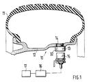
- FIG. 1 shows a cross section through a vehicle wheel with a tire pressure sensor according to the invention and the evaluation circuit in the block diagram
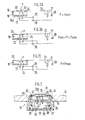
- FIG. 2 shows the schematic representation of the tire pressure sensor according to the invention with two contact pins and the resonant circuit connected thereto a) if the air pressure is too low, b) if the air pressure is sufficient, c) if the tire pressure is too high
- Figure 3 shows a further embodiment of a tire pressure sensor with a sleeve-shaped, coaxially arranged to the central contact pin contact body in cross section.
- FIG. 1 the detail of a motor vehicle wheel is shown in cross-section on a reduced scale and designated 10. It shows a tire 11 which is mounted on a wheel rim 12.
- a tire pressure sensor 13 is inserted in a threaded bore 14 of the wheel rim on an inward trimming of the wheel rim 12.
- a signal pickup 15 is attached to the wheel suspension of the vehicle, not shown, the end face of which is directed towards the tire pressure sensor 13 and couples a high-frequency oscillation generated in an evaluation circuit 16 into the tire pressure sensor 13 if the tire pressure sensor rotates with each revolution of the vehicle wheel 10 comes past.
- An electrical resonant circuit is accommodated in the tire pressure sensor 13, which is closed when a certain air pressure in the tire 11 is reached and then dampens the high-frequency vibration on the signal sensor 15 as a suction circuit.
- This cyclical damping corresponding to the rotating vehicle wheel 10 is monitored in the evaluation circuit 16 for each vehicle wheel. If there is no damping or the damping is reduced, a display 17 indicates which of the monitored tires is under-inflated.
- the schematic structure of the tire pressure sensor 13 and its function is illustrated and explained with the aid of FIG. 2.
- the tire pressure sensor essentially consists of a reference pressure chamber 18, the chamber housing 19 of steel for the tire is closed off by an electrically conductive membrane 20.
- a first contact pin 22 is arranged in an electrically insulated manner in a bushing 21, which acts as a first switching element with the membrane 20.
- the contact pin 22 and the membrane 20 are connected within the tire pressure sensor to a branch of an oscillating circuit 23 which is closed when the air pressure P in the tire is sufficient.
- a further contact pin 24 is fastened in the common bushing 21, insulated from the first contact pin 22.
- This contact pin 24 forms with the diaphragm 20 a second switching element, which is also connected to the resonant circuit 23 and only closes a further resonant circuit 23 when the diaphragm is severely deflected.
- the two adjacent contact pins 22 and 24 are connected to the resonant circuit 23 via a capacitor 25, 26 as a capacitive component with a common coil 27 as an inductive component, the other end of the coil 27 being connected to the membrane 20.
- Another capacitor 28 is connected in parallel with coil 27. This means three states: f1 (both switches open)> f2 (one switch closed)> f3 (both switches closed).
- the externally effective tire pressure P must bulge the membrane 20 against the pressure in the reference pressure chamber 18.
- FIG. 2a it is shown that at a tire pressure P which is below a minimum pressure Pmin predetermined by the lower threshold value of the tire pressure sensor 13, the membrane 20 is not arched inwards to such an extent that it has contact with the contact pins 22 and 23.
- the resonant circuit In this state of the tire pressure sensor 13 (P ⁇ Pmin), 23 is formed from the coil 27 and the capacitor 28.
- the resulting one Resonance frequency f1 is detected by the signal pickup 15 and the evaluation circuit 16. An indication of insufficient air pressure in the tire 11 of the corresponding wheel 10 thus appears on the display 17.
- the reference pressure chamber 18 is shown in a state that occurs. if the tire pressure P is greater than the minimum pressure Pmin specified by the lower threshold value but less than the pressure Pmax specified by the upper threshold value of the tire pressure sensor 10 (Pmin ⁇ P ⁇ Pmax).
- the membrane 20 is arched against the pressure in the reference pressure chamber 18 by the tire pressure P to such an extent that it bears against the central contact pin 22 and thereby closes a circuit branch through which the capacitor 26 is connected in parallel to the capacitor 28 to the coil 27 of the resonant circuit 23 becomes.
- the resonance frequency f2 occurring in this case is now detected by the signal pickup 15 with the evaluation circuit 16 and the display 17 shows that the monitored tire pressure is in order.
- FIG. 3 shows in a further exemplary embodiment the tire pressure sensor 13 screwed into the threaded bore 14 of the wheel rim 12 in cross section.
- the tire pressure sensor 13 consists of a housing 29, preferably made of insulating material, with a threaded attachment 30 for fastening in the threaded bore 14 of the wheel rim 12.
- the housing 29 carries on its side facing the tire 11 the reference pressure chamber 18 with the membrane 20, which is at the front of one perforated cover plate 31 is to be protected against mechanical damage.
- the cover plate 31 is fastened in front of the membrane 20 by a flange 32 of the housing 29.
- In the lower section of the sensor housing 29 there is an oscillating circuit chamber 33 with the coil 27 and the capacitors 25, 26 and 28, which in the arrangement shown in FIG.
- the middle contact pin 22 is melted together with a sleeve-shaped contact body 34 in a glass bushing 21 in the bottom 19a of the chamber housing 19.
- the contact pin 22 carries a contact ball 22a, which bears against a central contact zone of the membrane 20 due to a certain membrane deflection with sufficient air pressure in the tire 11 and thus closes a branch of the resonant circuit 23.
- the upper end of the sleeve-shaped contact body 34 arranged coaxially around the contact pin 22 is set back somewhat from the contact ball 22a of the central contact pin 22 or at the same height, so that the ring-shaped contact zone of the membrane 20 lying over it only becomes stronger when the membrane bends more. creates this contact body 34 and thus closes a further branch of the oscillating circuit 23.
- the sleeve-shaped contact body 34 is connected in parallel with the capacitor 25 and the middle contact pin 22 with the capacitor 26 to the coil 27 of the resonant circuit 23.
- the lower threshold value of the tire pressure sensor 13 is determined by the pressure of the gas filled into the reference pressure chamber 18 via a bore 35.
- the bore is closed pressure-tight by a ball 36 after the gas has been filled in.
- the difference between the lower and upper threshold value of the tire pressure sensor 13 is mainly determined by the distance that the membrane 20 still has when it contacts the contact ball 22a of the central contact pin 22 from the contact body 34 arranged coaxially thereto.
- this tire pressure sensor 13 also monitors whether the air pressure in the tire 11 lies between the two switching thresholds of the tire pressure sensor 13 or whether it falls below the lower switching threshold or exceeds the upper switching threshold. In addition to indicating that the tire pressure is too low for a leaky tire, it is also desirable to recognize an excessive tire pressure because this can damage the tire or impair its properties.
- the cap 31 is pressed in front of the membrane 20 and the membrane 20 has been blocked thereby.
- the membrane 20 rests on both contacts 22, 24 and gives a corresponding indication of a sensor defect or overpressure on the display 17 at the start of the process. Since the display 17 does not differentiate between a sensor defect and overpressure, the tire pressure is first reduced. If the display 17 remains unchanged, the membrane 20 is blocked. A complex check of the function of the tire pressure sensor 13 or an optical check by removing the sensor after each tire assembly can thus be avoided.
- the invention is not restricted to the exemplary embodiments shown.
- separate bushings can be selected for each switching element.
- the sleeve-shaped contact body can be made from a tube section or a bent sheet metal strip. It can also be designed as a pin that carries a contact ring below the membrane.
- a plurality of contact bodies with different distances from the membrane around the central contact pin can also be arranged, which sense different threshold values and close further circuits.
Landscapes
- Physics & Mathematics (AREA)
- General Physics & Mathematics (AREA)
- Engineering & Computer Science (AREA)
- Mechanical Engineering (AREA)
- Measuring Fluid Pressure (AREA)
Abstract
Claims (6)
Applications Claiming Priority (2)
| Application Number | Priority Date | Filing Date | Title |
|---|---|---|---|
| DE3723510 | 1987-07-16 | ||
| DE19873723510 DE3723510A1 (de) | 1987-07-16 | 1987-07-16 | Reifendrucksensor fuer kraftfahrzeuge |
Publications (2)
| Publication Number | Publication Date |
|---|---|
| EP0371966A1 EP0371966A1 (fr) | 1990-06-13 |
| EP0371966B1 true EP0371966B1 (fr) | 1991-04-17 |
Family
ID=6331688
Family Applications (1)
| Application Number | Title | Priority Date | Filing Date |
|---|---|---|---|
| EP19880903185 Expired - Lifetime EP0371966B1 (fr) | 1987-07-16 | 1988-04-22 | Detecteur de pression de pneus pour vehicules a moteur |
Country Status (6)
| Country | Link |
|---|---|
| US (1) | US5035137A (fr) |
| EP (1) | EP0371966B1 (fr) |
| JP (1) | JPH02504129A (fr) |
| DE (2) | DE3723510A1 (fr) |
| ES (1) | ES2007963A6 (fr) |
| WO (1) | WO1989000511A1 (fr) |
Families Citing this family (33)
| Publication number | Priority date | Publication date | Assignee | Title |
|---|---|---|---|---|
| DE3815677A1 (de) * | 1988-05-07 | 1989-11-16 | Bosch Gmbh Robert | Drucksensor zur erfassung des reifendrucks |
| US5274355A (en) * | 1992-02-05 | 1993-12-28 | Louis Galan | System for monitoring pressure and temperature of pneumatic tires on a moving vehicle |
| US5289161A (en) * | 1992-05-14 | 1994-02-22 | Huang Tien Tsai | Tire pressure indicator |
| JPH0719981A (ja) * | 1993-06-01 | 1995-01-20 | Nippondenso Co Ltd | 高温用圧力センサ |
| US5526692A (en) * | 1993-12-29 | 1996-06-18 | Keiser Corporation | Sensor |
| US5731754A (en) * | 1994-06-03 | 1998-03-24 | Computer Methods Corporation | Transponder and sensor apparatus for sensing and transmitting vehicle tire parameter data |
| US5844130A (en) * | 1996-04-03 | 1998-12-01 | Ssi Technologies | Apparatus for maintaining a constant radial distance between a transmitting circuit and an antenna coil |
| US6335690B1 (en) | 1997-01-15 | 2002-01-01 | Algonquin Scientific, Llc | Fluid sensing system |
| US6756892B2 (en) | 1997-01-15 | 2004-06-29 | Algonquin Scientific, Llc | Tire pressure sensing system |
| US6362732B1 (en) | 1997-01-15 | 2002-03-26 | Algonquin Scientific Llc | Tire pressure sensing system |
| US6124787A (en) * | 1997-01-15 | 2000-09-26 | Algonquin Scientific, Llc | Tire pressure sensing system |
| US6058768A (en) * | 1997-12-08 | 2000-05-09 | Huang; Tien-Tsai | Apparatus for detecting pressure condition in a pneumatic tire |
| EP0933236A1 (fr) * | 1998-02-02 | 1999-08-04 | Tien-Tsai Huang | Dispositif de détection de la condition de la pression d'un pneumatique |
| DE19853126B4 (de) * | 1998-11-18 | 2005-03-03 | Daimlerchrysler Ag | Verfahren zur Niveauregelung und Radfahrzeug mit einem Niveauregelsystem |
| US6166698A (en) * | 1999-02-16 | 2000-12-26 | Gentex Corporation | Rearview mirror with integrated microwave receiver |
| US8266465B2 (en) | 2000-07-26 | 2012-09-11 | Bridgestone Americas Tire Operation, LLC | System for conserving battery life in a battery operated device |
| US7161476B2 (en) | 2000-07-26 | 2007-01-09 | Bridgestone Firestone North American Tire, Llc | Electronic tire management system |
| DE10103974B4 (de) * | 2001-01-30 | 2006-03-09 | Key Safety Systems, Inc., Sterling Heights | Vorrichtung zur Prüfung des Fülldruckes eines Airbag-Gasspeichers |
| JP2003054230A (ja) * | 2001-08-16 | 2003-02-26 | Sumitomo Rubber Ind Ltd | タイヤ空気圧低下検出方法および装置、ならびにタイヤ減圧判定しきい値の選択プログラム |
| DE10146561A1 (de) * | 2001-09-21 | 2003-04-10 | Bayerische Motoren Werke Ag | Airbagsystem für ein Kraftrad |
| JP4372004B2 (ja) * | 2002-06-20 | 2009-11-25 | ブリヂストン・フアイヤーストーン・ノース・アメリカン・タイヤ・エルエルシー | 過熱したタイヤを検出する装置 |
| US6945104B2 (en) * | 2003-10-24 | 2005-09-20 | Lear Corporation | Attachment mechanism for a tire monitoring system |
| US7086412B2 (en) * | 2003-10-24 | 2006-08-08 | Lear Corporation | Snap-in grommet for a valve steam assembly |
| US20050087007A1 (en) * | 2003-10-24 | 2005-04-28 | Lear Corporation | Tire monitor system with spring retention clip |
| US7086411B2 (en) * | 2003-10-24 | 2006-08-08 | Lear Corporation | Snap-in grommet for a valve stem assembly |
| US7028541B2 (en) * | 2003-11-04 | 2006-04-18 | Lear Corporation | Tire pressure sensing component for detecting air pressure and related method |
| US7336164B2 (en) * | 2006-02-23 | 2008-02-26 | Dymos Co., Ltd. | Tire pressure monitoring system and sensor therefor |
| US7509850B1 (en) * | 2007-09-10 | 2009-03-31 | David Hui | Vehicle protection device directly formed on inflation valve |
| US20090085733A1 (en) * | 2007-09-27 | 2009-04-02 | Kisan Technologies, Inc. | Tire pressure, speed and acceleration monitoring system and method |
| US7937998B2 (en) * | 2009-03-19 | 2011-05-10 | Deere & Company | Sensor mount with self-tightening device |
| US20130167485A1 (en) * | 2011-12-28 | 2013-07-04 | James V. Ireland | Tire pressure sensor storge unit and method |
| US20150107338A1 (en) * | 2014-12-28 | 2015-04-23 | Ronald Billett | Pressure Measurement Device and Method |
| US11745549B2 (en) * | 2017-08-21 | 2023-09-05 | Sram. Llc | Pressure sensing assembly for a bicycle wheel |
Family Cites Families (9)
| Publication number | Priority date | Publication date | Assignee | Title |
|---|---|---|---|---|
| US2274557A (en) * | 1940-07-10 | 1942-02-24 | Morgan Raymond | Electric gauge |
| FR2280521A1 (fr) * | 1974-08-02 | 1976-02-27 | Vesnic Borislav | Avertisseur d'anomalies de pression des pneumatiques |
| FR2351399A1 (fr) * | 1976-05-12 | 1977-12-09 | Lucas Electrical Co Ltd | Transducteur de pression de fluide |
| US4163964A (en) * | 1977-03-21 | 1979-08-07 | Texas Instruments Incorporated | Pneumatic or hydraulic pressure sensors with several thresholds of response |
| DE2832447A1 (de) * | 1978-07-24 | 1980-02-14 | Bosch Gmbh Robert | Pneumatisch betaetigbarer druckschalter |
| DE3243854A1 (de) * | 1982-11-26 | 1984-05-30 | Robert Bosch Gmbh, 7000 Stuttgart | Pneumatisch betaetigbarer druckschalter zur reifendruckueberwachung |
| DE3412949A1 (de) * | 1984-04-06 | 1985-10-17 | Dr.Ing.H.C. F. Porsche Ag, 7000 Stuttgart | Vorrichtung zur kontrolle des luftdrucks von fahrzeugreifen |
| DE3507253C1 (de) * | 1985-03-01 | 1986-07-03 | Dr.Ing.H.C. F. Porsche Ag, 7000 Stuttgart | Pneumatisch betaetigter Druckschalter zur Reifendruckueberwachung |
| DE3738413C1 (en) * | 1987-11-12 | 1989-02-16 | Bosch Gmbh Robert | Tyre pressure sensor for motor vehicles |
-
1987
- 1987-07-16 DE DE19873723510 patent/DE3723510A1/de not_active Withdrawn
-
1988
- 1988-04-22 EP EP19880903185 patent/EP0371966B1/fr not_active Expired - Lifetime
- 1988-04-22 DE DE8888903185T patent/DE3862470D1/de not_active Expired - Lifetime
- 1988-04-22 US US07/459,753 patent/US5035137A/en not_active Expired - Fee Related
- 1988-04-22 JP JP63503299A patent/JPH02504129A/ja active Pending
- 1988-04-22 WO PCT/DE1988/000241 patent/WO1989000511A1/fr not_active Ceased
- 1988-07-15 ES ES8802230A patent/ES2007963A6/es not_active Expired
Also Published As
| Publication number | Publication date |
|---|---|
| DE3862470D1 (de) | 1991-05-23 |
| US5035137A (en) | 1991-07-30 |
| DE3723510A1 (de) | 1989-01-26 |
| ES2007963A6 (es) | 1989-07-01 |
| EP0371966A1 (fr) | 1990-06-13 |
| WO1989000511A1 (fr) | 1989-01-26 |
| JPH02504129A (ja) | 1990-11-29 |
Similar Documents
| Publication | Publication Date | Title |
|---|---|---|
| EP0371966B1 (fr) | Detecteur de pression de pneus pour vehicules a moteur | |
| EP0333708B1 (fr) | Detecteur de la pression de pneus de vehicules a moteur | |
| DE3884506T2 (de) | Reifenprüfeinrichtung. | |
| DE3812633C2 (fr) | ||
| DE3151254C2 (de) | Prüfvorrichtung für den Reifenluftdruck von Rädern an Fahrzeugen und Verfahren für eine derartige Vorrichtung | |
| DE2257341A1 (de) | Vorrichtung zum automatischen erkennen unnormaler zustaende in fahrzeugreifen | |
| DE3941780C2 (de) | Druckschalter, insbesondere für eine Warnvorrichtung für Druckverlust in Fahrzeugreifen | |
| DE3543866A1 (de) | Reifendrucksensor fuer kraftfahrzeuge | |
| EP0391922B1 (fr) | Capteur de la pression des pneus de vehicules a moteur | |
| DE3507253C1 (de) | Pneumatisch betaetigter Druckschalter zur Reifendruckueberwachung | |
| WO1989010852A1 (fr) | Manometre de detection de la pression de pneus | |
| DE112011102738T5 (de) | Elektrodenvorrichtung, Drucksensor und Druckmessgerät | |
| EP0402363B1 (fr) | Detecteur de la pression des pneumatiques d'un vehicule automobile | |
| CH665905A5 (de) | Oberschalige elektrische waage. | |
| EP0455636B1 (fr) | Controleur de la pression des pneus de vehicules | |
| DE4308353C1 (de) | An einem Fahrzeug anzubringender Sensor zur Erkennung einer mechanischen Formveränderung | |
| DE4445819C2 (de) | Abstands/Positions-Meßvorrichtung | |
| EP0335082A2 (fr) | Capteur de pression pour surveiller une pression de pneumatiques, en particulier de pneumatiques de véhicules | |
| DE3709981A1 (de) | Ueberwachungseinrichtung zur erfassung anomaler druckverhaeltnisse von fahrzeugreifen | |
| EP0157205B1 (fr) | Dispositif de surveillance de la pression d'air de pneumatiques de véhicules | |
| DE3543865A1 (de) | Reifendrucksensor fuer kraftfahrzeuge | |
| DE3738413C1 (en) | Tyre pressure sensor for motor vehicles | |
| DE102018107884A1 (de) | Bedienvorrichtung zum Bedienen von zumindest einem Gerät eines Kraftfahrzeugs, wobei eine Bedienung in Abhängigkeit von zwei physikalischen Parametern durchführbar ist, Kraftfahrzeug sowie Verfahren | |
| DE10110279A1 (de) | Abschirmungs- und Federschnittstelle zwischen einer Zündkerze und einer Stiftspule | |
| WO1996021937A1 (fr) | Interrupteur mecanique actionne par l'acceleration |
Legal Events
| Date | Code | Title | Description |
|---|---|---|---|
| PUAI | Public reference made under article 153(3) epc to a published international application that has entered the european phase |
Free format text: ORIGINAL CODE: 0009012 |
|
| 17P | Request for examination filed |
Effective date: 19891229 |
|
| AK | Designated contracting states |
Kind code of ref document: A1 Designated state(s): DE FR GB IT SE |
|
| 17Q | First examination report despatched |
Effective date: 19900926 |
|
| GRAA | (expected) grant |
Free format text: ORIGINAL CODE: 0009210 |
|
| AK | Designated contracting states |
Kind code of ref document: B1 Designated state(s): DE FR GB IT SE |
|
| PGFP | Annual fee paid to national office [announced via postgrant information from national office to epo] |
Ref country code: FR Payment date: 19910430 Year of fee payment: 4 |
|
| ET | Fr: translation filed | ||
| GBT | Gb: translation of ep patent filed (gb section 77(6)(a)/1977) | ||
| REF | Corresponds to: |
Ref document number: 3862470 Country of ref document: DE Date of ref document: 19910523 |
|
| PGFP | Annual fee paid to national office [announced via postgrant information from national office to epo] |
Ref country code: DE Payment date: 19910625 Year of fee payment: 4 |
|
| ITF | It: translation for a ep patent filed | ||
| PGFP | Annual fee paid to national office [announced via postgrant information from national office to epo] |
Ref country code: SE Payment date: 19910712 Year of fee payment: 4 |
|
| PLBE | No opposition filed within time limit |
Free format text: ORIGINAL CODE: 0009261 |
|
| STAA | Information on the status of an ep patent application or granted ep patent |
Free format text: STATUS: NO OPPOSITION FILED WITHIN TIME LIMIT |
|
| RAP4 | Party data changed (patent owner data changed or rights of a patent transferred) |
Owner name: ROBERT BOSCH GMBH |
|
| 26N | No opposition filed | ||
| PG25 | Lapsed in a contracting state [announced via postgrant information from national office to epo] |
Ref country code: GB Effective date: 19920422 |
|
| PG25 | Lapsed in a contracting state [announced via postgrant information from national office to epo] |
Ref country code: SE Effective date: 19920423 |
|
| GBPC | Gb: european patent ceased through non-payment of renewal fee | ||
| PG25 | Lapsed in a contracting state [announced via postgrant information from national office to epo] |
Ref country code: FR Effective date: 19921230 |
|
| PG25 | Lapsed in a contracting state [announced via postgrant information from national office to epo] |
Ref country code: DE Effective date: 19930101 |
|
| REG | Reference to a national code |
Ref country code: FR Ref legal event code: ST |
|
| EUG | Se: european patent has lapsed |
Ref document number: 88903185.2 Effective date: 19921108 |
|
| PG25 | Lapsed in a contracting state [announced via postgrant information from national office to epo] |
Ref country code: IT Free format text: LAPSE BECAUSE OF NON-PAYMENT OF DUE FEES Effective date: 20050422 |