EP0263971B1 - Procédé et appareil pour planer une bande métallique entrant dans un four de recuit en continu - Google Patents
Procédé et appareil pour planer une bande métallique entrant dans un four de recuit en continu Download PDFInfo
- Publication number
- EP0263971B1 EP0263971B1 EP87113125A EP87113125A EP0263971B1 EP 0263971 B1 EP0263971 B1 EP 0263971B1 EP 87113125 A EP87113125 A EP 87113125A EP 87113125 A EP87113125 A EP 87113125A EP 0263971 B1 EP0263971 B1 EP 0263971B1
- Authority
- EP
- European Patent Office
- Prior art keywords
- metal strip
- leveling
- component
- line speed
- joint
- Prior art date
- Legal status (The legal status is an assumption and is not a legal conclusion. Google has not performed a legal analysis and makes no representation as to the accuracy of the status listed.)
- Expired - Lifetime
Links
- 239000002184 metal Substances 0.000 title claims description 149
- 238000000137 annealing Methods 0.000 title claims description 34
- 238000000034 method Methods 0.000 title claims description 16
- 230000013011 mating Effects 0.000 claims description 6
- 238000009499 grossing Methods 0.000 claims description 3
- 230000000712 assembly Effects 0.000 description 9
- 238000000429 assembly Methods 0.000 description 9
- 230000000881 depressing effect Effects 0.000 description 8
- 238000010438 heat treatment Methods 0.000 description 7
- 238000005452 bending Methods 0.000 description 4
- 238000001816 cooling Methods 0.000 description 4
- 238000009826 distribution Methods 0.000 description 4
- 238000011144 upstream manufacturing Methods 0.000 description 3
- 238000010276 construction Methods 0.000 description 2
- 230000007547 defect Effects 0.000 description 2
- 238000002791 soaking Methods 0.000 description 2
- 238000003466 welding Methods 0.000 description 2
- 230000015572 biosynthetic process Effects 0.000 description 1
- 238000005304 joining Methods 0.000 description 1
- 239000000463 material Substances 0.000 description 1
- 238000012986 modification Methods 0.000 description 1
- 230000004048 modification Effects 0.000 description 1
- 238000005096 rolling process Methods 0.000 description 1
- 239000005028 tinplate Substances 0.000 description 1
Images


Classifications
-
- C—CHEMISTRY; METALLURGY
- C21—METALLURGY OF IRON
- C21D—MODIFYING THE PHYSICAL STRUCTURE OF FERROUS METALS; GENERAL DEVICES FOR HEAT TREATMENT OF FERROUS OR NON-FERROUS METALS OR ALLOYS; MAKING METAL MALLEABLE, e.g. BY DECARBURISATION OR TEMPERING
- C21D9/00—Heat treatment, e.g. annealing, hardening, quenching or tempering, adapted for particular articles; Furnaces therefor
- C21D9/52—Heat treatment, e.g. annealing, hardening, quenching or tempering, adapted for particular articles; Furnaces therefor for wires; for strips ; for rods of unlimited length
-
- B—PERFORMING OPERATIONS; TRANSPORTING
- B21—MECHANICAL METAL-WORKING WITHOUT ESSENTIALLY REMOVING MATERIAL; PUNCHING METAL
- B21D—WORKING OR PROCESSING OF SHEET METAL OR METAL TUBES, RODS OR PROFILES WITHOUT ESSENTIALLY REMOVING MATERIAL; PUNCHING METAL
- B21D1/00—Straightening, restoring form or removing local distortions of sheet metal or specific articles made therefrom; Stretching sheet metal combined with rolling
- B21D1/05—Stretching combined with rolling
-
- C—CHEMISTRY; METALLURGY
- C21—METALLURGY OF IRON
- C21D—MODIFYING THE PHYSICAL STRUCTURE OF FERROUS METALS; GENERAL DEVICES FOR HEAT TREATMENT OF FERROUS OR NON-FERROUS METALS OR ALLOYS; MAKING METAL MALLEABLE, e.g. BY DECARBURISATION OR TEMPERING
- C21D7/00—Modifying the physical properties of iron or steel by deformation
- C21D7/02—Modifying the physical properties of iron or steel by deformation by cold working
-
- C—CHEMISTRY; METALLURGY
- C21—METALLURGY OF IRON
- C21D—MODIFYING THE PHYSICAL STRUCTURE OF FERROUS METALS; GENERAL DEVICES FOR HEAT TREATMENT OF FERROUS OR NON-FERROUS METALS OR ALLOYS; MAKING METAL MALLEABLE, e.g. BY DECARBURISATION OR TEMPERING
- C21D9/00—Heat treatment, e.g. annealing, hardening, quenching or tempering, adapted for particular articles; Furnaces therefor
- C21D9/52—Heat treatment, e.g. annealing, hardening, quenching or tempering, adapted for particular articles; Furnaces therefor for wires; for strips ; for rods of unlimited length
- C21D9/54—Furnaces for treating strips or wire
- C21D9/56—Continuous furnaces for strip or wire
Definitions
- the present invention relates generally to a method device for leveling a series of metal strip to subject heat treatment, such as annealing. More specifically, the invention relates to a technic for effectively performing metal strip leveling operation with avoidance of breakage at welded joint, defect in the series of metal strip.
- a plurality of hearth rolls are arranged in a continuous annealing furnace for defining a zig-zag path through known heat treatment stages, such as a heating stage, a soaking stage maintaining the metal strip at constant heated temperature, a cooling stage and so forth.
- the metal strip is wound around the hearth rolls and runs through the zig-zag path in the annealing furnace to be subject heat treatment.
- the metal strip at the zone cross to the inlet has relatively low temperature.
- the temperature at the transverse edge positions of the hearth roll tends to become much higher than that at the transverse central portion.
- This temperature difference between the edge portions and the central portion increases as increasing the line speed.
- This reduction of the crown tends to lead unbalance of tension to be exerted on the metal strip in transverse direction in the case that the metal strip is in the configuration of edge wave or center wave. Unbalance tension tends to cause meander of the metal strip in the path.
- the line speed to feed the metal strip through the annealing furnace has to be lowered in order to minimize temperature difference between the edge portions and the central portions of the hearth roll. This clearly cause lowering efficiency of the annealing furnace.
- possibility of the meander of the metal strip can be reduced by providing greater magnitude of the initial crown on the periphery of the hearth roll. This may allow to maintain satisfactory line speed.
- the crown magnitude tends to be excessive at the high temperature zone to cause heat buckle when line speed is lowered in some reason, such as for welding the strips.
- the meander of the metal strip in the annealing furnace is also caused due to configuration of the metal strip, such as bending, transverse curve and so forth. If the configuration of the metal strip is not suitable for passing through the annealing furnace to cause uneven contact with the hearth roll surface, meander of the metal strip is caused even when the crown magnitude is sufficient. This tendency increases as increasing the line speed.
- tension leveler devices are provided.
- tension leveler devices exert substantial tension, e.g. 20 kg/mm2.
- Such high tension to be exerted on the metal strip tends to cause breakage at the welded joint between leading and trailing metal coils. defects on the metal strip.
- leveling rolls in the tension leveler tends to be damaged due to high tension.
- slow-down of the line speed necessarily causes the lowering of the efficiency of the annealing furnace.
- releasing of the leveling rolls necessarily feed the metal strip with unleveled portions to cause meander in the annealing furnace.
- the respective tension reference values of the preceding and succeeding strip members are set in setting devices and finally, the bridle roll is moved away from the strip to lower the tension to a predetermined value.
- the afore-mentioned prior art does not comprise a leveling roll assembly for leveling a metal strip, but merely comprises tension applying bridle rolls for exerting a predetermined magnitude of tension force to a metal Strip.
- Another object of the present invention to provide a method and device to perform tension leveling operation for the metal strip which successfully eliminates the metal strip to cause meander in the annealing furnace by controlling a tension to be exerted on the metal strip so that the expansion of the metal strip due to the exerted tension can be set in relation to open and close positions of the leveling rolls to release the rolls from the metal strip at the welded joint portion in order to establish optimal relationship.
- a further object of the invention is to provide a level device which is suitable for implementing quick open and quick close operation in the leveling operation for avoiding welded joint of the metal strip without requiring lowering of line speed.
- a method for leveling a metal strip performs leveling operation by opening leveling rolls at a predetermined position relative to the welded joint and close at a predetermined position relative to the welded joint.
- a tension to be exerted on the metal strip while the leveling rolls are held open is set at a given value in relation to the metal strip length where the leveling rolls are held open.
- the tension to be exerted on the metal strip while the leveling rolls is selected so that the tension may cause a given elongation on the metal strip and whereby the metal strip is leveled.
- a leveling device which is applicable for implementing the leveling process including quick open and quick close at the welded joint of the strips.
- the leveling device according to the present invention features in that the leveling rolls as held open and thus released from the metal strip is self-propelled to rotate.
- a method for leveling a metal strip to be fed into an annealing furnace, which metal strip is formed into a series of strip by connecting coils at a joint comprises the steps of:
- a leveling roll assemblies which is constituted of a first and second roll components disposed between opposite sides of a path through which the metal strip is fed;
- the rotation speed of the first component is variable depending upon a line speed of the metal strip.
- the rotation speed of the first component is so adjusted as to have a given difference relative to the line speed so that the speed difference is reduced as increasing the line speed.
- the first component is released from the metal strip at a point a given distance ahead the joint the contacted to the metal strip at a point a given distance after the joint.
- a method for leveling a metal strip to be fed into an annealing furnace, which metal strip is formed into a series of strip by connecting coils at a join comprises the steps of;
- a leveling roll assemblies which is constituted of a first and second roll components disposed between opposite sides of a path through which the metal strip is fed;
- the leveling operation is to be performed for smoothing the surface of the metal strip to have a steepness less than about 1%, where steepness means a ratio of the height of the peak of projecting portion on the surface of the metal strip versus a distance from the peak to bottom of adjacent depression.
- a leveling device for leveling a metal strip to be fed into an annealing furnace, which metal strip is formed into a series of strip by connecting coils at a join, comprises a leveling roll assembly which is constituted of a first and second roll components disposed between opposite sides of a path through which the metal strip is fed, means for exerting a predetermined magnitude of tension force to the metal strip during leveling operation, means for depressing the first and second components of the leveling roll assembly with a predetermined pressure for leveling the metal strip, means for releasing the first component of the leveling roller assembly from the mating surface of the metal strip for releasing the metal strip from depressing pressure, at a joint of the series of metal strip, and means for rotatingly driving the first component while it is released from the metal strip.
- a leveling device for leveling a metal strip to be fed into an annealing furnace, which metal strip is formed into a series of strip by connecting coils at a join, comprises a leveling roll assembly which is constituted of a first and second roll components disposed between opposite sides of a path through which the metal strip is fed, means for exerting a predetermined magnitude of tension force to the metal strip during leveling operation, means for depressing the first and second components of the leveling roll assembly with a predetermined pressure for leveling the metal strip, means for releasing the first component of the leveling roller assembly from the mating surface of the metal strip for releasing the metal strip from depressing pressure, at a joint of the series of metal strip, and means of adjusting the tension force to be exerted metal strip during the leveling operation to adjust an elongation of the metal strip in a predetermined relationship with the distance to satisfy the following equation:
- Fig. 1 is a fragmentary illustration of a general construction of an inlet portion of an annealing furnace, to which the preferred embodiment of a method for leveling a metal strip and a leveling device therefor are applicable;
- Fig. 2 is an illustration of the annealing furnace for performing continuous annealing for a series of metal strip
- Fig. 3 is an illustration of an arrangement of leveling rollers of the preferred embodiment of the leveling device according to the invention.
- Fig.4 is a graph showing steepness of the metal strip, which steepness is defined by a ratio of the height of a peak of the uneveness (H) versus pitch between peak and adjacent bottom (P);
- Fig. 5 is a graph showing elongation ⁇ % of the metal strip relative to a distance from leveling rollers open point and/or close point to a welded joint on the metal strip;
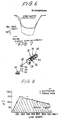
- Fig. 6 is a chart showing axial direction temperature distribution of the hearth roll at the position adjacent the inlet of the annealing furnace
- Fig. 7 is a perspective view of the preferred embodiment of a leveling roller assembly to be employed in the preferred embodiment of the leveling device according to the invention.
- Fig. 8 is a graph showing relationship between a speed difference between the metal strip and the leveling roll and a line speed.
- a annealing furnace 10 to which the preferred embodiment of a method for leveling a metal strip 12 and a leveling device 14 for implementing the preferred embodiment of the leveling method according to the invention, has an inlet side looper 16 at the position upstream of a furnace chamber 18.
- the preferred embodiment of the leveling device 14 is provided at a position upstream of the inlet side looper 16, the leveling device 14 to be employed is a tension leveling device.
- the furnace chamber 18 is divided into a plurality of zones, i.e. heating zone 18a, a soaking zone 18b, a moderate cooling zone 18c and quick cooling zone 18d.
- a plurality of hearth rolls 18e are arranged in the furnace chamber 18 to define a zig zag path for the metal strip 12.
- the hearth rolls are separated into two groups, in which one group is located adjacent the ceiling of the annealing furnace and the other group of rolls are located adjacent the floor of the furnace. Therefore, the rolls in the one group is distanced from preceding the trailing rolls in other group at a predetermined span L.
- the preferred embodiment of the leveling device 14 comprises a plurality of leveling roll assemblies 20.
- Each leveling roller assembly comprises a work roll 22, an intermediate rolls 24, back-up rolls 26 and deflector rolls 28.
- the deflector rolls 28 forming a deflector roll assembly 30 are oriented opposite side to the work roll 22, the intermediate roll 24 and the back-up rolls 26 which forms a work roll assembly 32 with respect to the metal strip path.
- the leveling roll assemblies 20 are arranged along a metal strip path in the leveling device 14 with a given interval.
- the leveling roll assemblies 20 are respectively associated with known mechanism for shifting the work roll assembly 32 toward and away from the deflector roll assembly 30 so as to release the work rolls from the metal strip while the welding joint 34 on the metal strip 12 passes through the leveling device 14.
- Bridle rolls 36 and 37 are provided at upstream end and downstream end of the leveling device 14 for controlling tension to be exerted on the metal strip 12 passing through the leveling device.
- the leveling roll assemblies 20 is operated to be open at a point 40 of the metal strip x (m) ahead of the welded joint 34 and return to closed position after x (m) from the welded joint at a point 42. Namely, when the point 40 of the metal strip arrives the leveling device 14, the leveling roll assemblies 20 are operated at the open position, in which the work roll assembly 32 are shifted away fro the deflector roll assembly 30 to make the metal strip free from rolling pressure. The leveling roll assemblies 20 are operated to the closed position to contact the work roll 22 and the deflector rolls 28 onto the opposite sides of the metal strip when the point 42 pass the outlet of the leveling device.
- the depression and so forth are set so that the steepness which is the ratio of the height of the peak H of the projecting uneveness versus the pitch P from the peak to the bottom of the depression, is suitable for satisfactorily high line speed in the annealing furnace.
- the steepness is less than or equal to 1.0%
- the line speed in the annealing furnace was higher than or equal to 550 m/min. This is satisfactory for obtaining high efficiency of the annealing furnace.
- the preferred steepness is 1.0% or smaller.
- the bridle rolls 36 and 37 are controlled to provide a tension for the metal strip passing the leveling device.
- the tension is so determined as to provide a given elongation expansion ⁇ on the metal strip.
- the metal strip elongation ⁇ (%) represents magnitude of tension force to be exerted on the metal strip.
- the tension force is determined to satisfy the following equation:
- the work rolls 22 are idle roll rotatingly driven by the metal strip fed at a given line speed. Therefore, the rotation speed of the work roll was determined corresponding to the line speed of the metal strip.
- substantial thrusting force may be exerted onto the bearing section of the work roll when it is released from the metal strip in the quick open operation.
- the work roll stops.
- the leveling roll assembly 20 to be employed in the preferred embodiment of the invention has a driving mechanism 50 for driving the work roll 22 at least when the leveling roll assembly 20 is held open position and thus the work roll 22 is held away from the metal strip.
- the driving mechanism 50 comprises an electric motor 52 which drives a driving sproket 54.
- the driving sproket 54 is connected to a driven sproket 56 associated with a power distribution mechanism 58, via a chain 60.
- the power distribution mechanism 58 is associated with the back-up rolls 26 to rotatingly drive the latter. Since rotation torque thus exerted on the back-up rolls 26 are transmitted to the work roll 22 via the intermediate rolls 24.
- a clutch 62 may be provided between the driven sproket 56 and the power distribution mechanism 58 for establishing and releasing the power train in synchronism with quick open and quick close operation of the leveling roll assembly.
- Fig. 8 shows a graph showing a relationship between the line speed LS and the speed difference ⁇ S (m/min) as a result of experimentation.
- the line speed is lower than or equal to 150 m/min, scratch was not formed even when the work roll 22 is not driven to rotate.
- the line speed is higher than 150 m/min, scratches were made when the work roll is held stopped.
- higher speed of rotation was required to reduce the difference ⁇ S. Namely, when the speed difference ⁇ S in relation to the line speed is held in a hutched range, scratch will never formed on the metal strip. Therfore, the speed of rotation of the work roll is set to satisfy the following formulae: When LS ⁇ 150 m/min,
Landscapes
- Chemical & Material Sciences (AREA)
- Engineering & Computer Science (AREA)
- Mechanical Engineering (AREA)
- Crystallography & Structural Chemistry (AREA)
- Materials Engineering (AREA)
- Metallurgy (AREA)
- Organic Chemistry (AREA)
- Physics & Mathematics (AREA)
- Thermal Sciences (AREA)
- Heat Treatment Of Strip Materials And Filament Materials (AREA)
Claims (6)
- Procédé de planage d'une bande de métal pénétrant dans un four de recuit, qui est constituée d'une succession de tronçons soudés, comportant les étapes consistant à :
prévoir un ensemble de rouleaux de planage qui comporte un premier (32) et un second (30) éléments à rouleaux disposés entre des côtés opposés d'un trajet à travers lequel progresse la bande de métal ;
prévoir des moyens pour exercer une tension d'amplitude prédéterminée sur ladite bande de métal durant l'opération de planage;
pousser lesdits premier et second éléments dudit ensemble de rouleaux de planage avec une pression prédéterminée pour planer ladite bande de métal;
dégager ledit premier élément (32) dudit ensemble de rouleaux de planage de la surface en regard de ladite bande de métal pour libérer ladite bande de métal de la pression d'application en un point situé à une distance donnée en avant de la soudure (34) et remettre en contact ledit premier élément (32) avec ladite bande de métal en un point (42) situé à une distance donnée derrière ladite soudure, et
entraîner en rotation au moins ledit premier élément (32) tandis qu'il est dégagé de ladite bande de métal, dans lequel la vitesse de rotation dudit premier élément (32) est réglée de manière à posséder une différence de vitesse donnée par rapport à la vitesse linéaire de ladite bande de métal de sorte que ladite différence de vitesse soit réduite lorsque la vitesse linéaire augmente, et
dans lequel ladite vitesse de rotation du premier élément (32) est réglée de manière à satisfaire à la formule suivante
△ S ≦αµρ¨ - a.x LS+b
où△S est la différence de vitesse,LS est la vitesse linéaire de la bande de métal,a = 0,124; etb = 168,6lorsque la vitesse linéaire est supérieure à 150 m/minute. - Procédé selon la revendication 1, qui comporte en outre une étape de réglage de ladite tension à exercer sur la bande de métal durant ladite opération de planage pour régler un allongement de ladite bande de métal selon un relation prédéterminée avec ladite distance pour satisfaire à l'équation suivante:
∅ > 0,0082 (x/8L) 1,45
où∅ est l'allongement (%);x est ladite distance; etL est la distance entre les rouleaux de sole dans ledit four de recuit. - Procédé selon la revendication 1, dans lequel ladite opération de planage doit être effectuée pour lisser la surface de ladite bande de métal pour présenter une inclinaison inférieure à environ 1%.
- Procédé selon la revendication 2, dans lequel ladite opération de planage doit être effectuée pour lisser la surface de ladite bande de métal pour présenter une inclinaison inférieure à environ 1%.
- Dispositif de planage pour planer une bande de métal pénétrant dans un four de recuit, laquelle bande de métal est constituée d'une succession de tronçons qui sont reliés par soudure (34), comportant
un ensemble de rouleaux de planage (20) qui est constitué de premier et second éléments à rouleaux (32, 30) disposés entre des côtés opposés d'un trajet à travers lequel progresse la bande de métal ;
des moyens (36,37) pour exercer une tension d'amplitude prédéterminée sur ladite bande de métal durant l'opération de planage;
des moyens pour pousser lesdits premier et second éléments dudit ensemble de rouleaux de planage (20) avec une pression prédéterminée pour planer ladite bande de métal;
des moyens pour dégager ledit premier élément (32) dudit ensemble de rouleaux de planage (20) de la surface en regard de ladite bande de métal pour libérer ladite bande de métal de ladite pression à une soudure (34) desdits tronçons de bande de métal;
des moyens (52 à 58) pour entraîner en rotation au moins ledit premier élément (32) tandis qu'il est dégagé de ladite bande de métal, dans lequel lesdits moyens d'entraînement sont aptes à régler la vitesse de rotation dudit premier élément (32) de manière à présenter une différence de vitesse donnée par rapport à la vitesse linéaire de ladite bande de métal de sorte que ladite différence de vitesse soit réduite lorsque la vitesse linéaire augmente; et
dans lequel lesdits moyens d'entraînement (52 à 58) sont commandés pour régler la vitesse de rotation dudit premier élément (32) pour satisfaire à la formule suivante:
△s ≦αµρ¨ -a. LS + b
où△S est la différence de vitesse;LS est la vitesse linéaire de la bande de métal;a = 0,124; etB = 168,6lorsque la vitesse linéaire est supérieure à 150 m/minute. - Dispositif de planage selon la revendication 5, dans lequel ledit premier élément (32) est dégagé de ladite bande de métal en un point (40) à une distance donnée en avant de la soudure (34) et remis en contact de ladite bande de métal en un point (42) à une distance donnée derrière ladite soudure.
Applications Claiming Priority (4)
| Application Number | Priority Date | Filing Date | Title |
|---|---|---|---|
| JP211909/86 | 1986-09-09 | ||
| JP21190986 | 1986-09-09 | ||
| JP23012586A JPS6384729A (ja) | 1986-09-30 | 1986-09-30 | テンシヨンレベラの運転方法 |
| JP230125/86 | 1986-09-30 |
Publications (2)
| Publication Number | Publication Date |
|---|---|
| EP0263971A1 EP0263971A1 (fr) | 1988-04-20 |
| EP0263971B1 true EP0263971B1 (fr) | 1991-02-27 |
Family
ID=26518901
Family Applications (1)
| Application Number | Title | Priority Date | Filing Date |
|---|---|---|---|
| EP87113125A Expired - Lifetime EP0263971B1 (fr) | 1986-09-09 | 1987-09-08 | Procédé et appareil pour planer une bande métallique entrant dans un four de recuit en continu |
Country Status (7)
| Country | Link |
|---|---|
| US (1) | US4870850A (fr) |
| EP (1) | EP0263971B1 (fr) |
| KR (1) | KR950013189B1 (fr) |
| AU (1) | AU594498B2 (fr) |
| BR (1) | BR8704695A (fr) |
| DE (1) | DE3768197D1 (fr) |
| ES (1) | ES2021315B3 (fr) |
Families Citing this family (4)
| Publication number | Priority date | Publication date | Assignee | Title |
|---|---|---|---|---|
| US5724845A (en) * | 1996-08-12 | 1998-03-10 | Kawasaki Steel Corporation | Bowing correction apparatus for temper rolling mill |
| CN1065460C (zh) * | 1996-08-15 | 2001-05-09 | 川崎制铁株式会社 | 调质轧机的弯曲调整装置 |
| AU714204B2 (en) * | 1996-08-15 | 1999-12-23 | Kawasaki Steel Corporation | Bowing correction apparatus for temper rolling mill |
| DE10124836C5 (de) * | 2001-05-22 | 2007-07-19 | Bwg Bergwerk- Und Walzwerk-Maschinenbau Gmbh | Verfahren zum Beseitigen von Querkrümmungen in einem Metallband |
Family Cites Families (12)
| Publication number | Priority date | Publication date | Assignee | Title |
|---|---|---|---|---|
| US2001637A (en) * | 1933-01-11 | 1935-05-14 | United Eng Foundry Co | Rolling mill feeding apparatus |
| FR1014215A (fr) * | 1949-02-22 | 1952-08-12 | Nordisk Aluminium Ind As | Procédé et dispositif permettant le passage continu d'un ruban métallique entre deux rouleaux |
| US3104567A (en) * | 1960-09-19 | 1963-09-24 | United Eng Foundry Co | Rolling mill screwdown apparatus |
| US3171464A (en) * | 1962-09-04 | 1965-03-02 | Voss Engineering Co | Method of flattening metal strip or sheet |
| DE1235847B (de) * | 1964-12-28 | 1967-03-09 | Ungerer Irma | Richtmaschine |
| US3421925A (en) * | 1965-07-30 | 1969-01-14 | Westinghouse Electric Corp | Method for producing improved metallic strip material |
| US3416340A (en) * | 1966-06-08 | 1968-12-17 | Voss Engineering Company | Automatic control and indicating systems for roller levelers |
| US3584853A (en) * | 1968-10-11 | 1971-06-15 | Westinghouse Electric Corp | Tracking system for strip processing lines |
| AT314453B (de) * | 1971-07-09 | 1974-04-10 | Bwg Bergwerk Und Walzwek Masch | Verfahren und Vorrichtung zum Reduzieren von Blechbändern in Bandstraßen |
| ZA726064B (en) * | 1971-09-22 | 1973-05-30 | Gen Electric | Method and system for controlling strip thickness in a continuous tandem rolling mill |
| JPS5914528B2 (ja) * | 1979-04-20 | 1984-04-05 | 株式会社東芝 | 連続長尺材の張力設定制御装置 |
| JPS6076223A (ja) * | 1983-09-30 | 1985-04-30 | Sumitomo Electric Ind Ltd | 線材の接続部の断線を防止する方法 |
-
1987
- 1987-09-04 US US07/094,662 patent/US4870850A/en not_active Expired - Fee Related
- 1987-09-08 DE DE8787113125T patent/DE3768197D1/de not_active Expired - Fee Related
- 1987-09-08 ES ES87113125T patent/ES2021315B3/es not_active Expired - Lifetime
- 1987-09-08 EP EP87113125A patent/EP0263971B1/fr not_active Expired - Lifetime
- 1987-09-08 KR KR1019870009900A patent/KR950013189B1/ko not_active Expired - Fee Related
- 1987-09-09 AU AU78200/87A patent/AU594498B2/en not_active Ceased
- 1987-09-09 BR BR8704695A patent/BR8704695A/pt not_active IP Right Cessation
Also Published As
| Publication number | Publication date |
|---|---|
| US4870850A (en) | 1989-10-03 |
| EP0263971A1 (fr) | 1988-04-20 |
| AU7820087A (en) | 1988-03-17 |
| BR8704695A (pt) | 1988-04-26 |
| DE3768197D1 (de) | 1991-04-04 |
| ES2021315B3 (es) | 1991-11-01 |
| KR880004109A (ko) | 1988-06-01 |
| AU594498B2 (en) | 1990-03-08 |
| KR950013189B1 (ko) | 1995-10-25 |
Similar Documents
| Publication | Publication Date | Title |
|---|---|---|
| KR960016462B1 (ko) | 강 스트립의 연속어닐링장치 및 그의 장력제어장치와 장력제어방법 | |
| EP0688625A1 (fr) | Procédé de soudage résistif par projection | |
| CN113798981B (zh) | 一种快速消除炉辊表面结瘤的方法 | |
| CA1280190C (fr) | Methode et dispositif pour controler la traction subie par un feuillard lors du passage dans un four de recuit en continu | |
| JPS607693B2 (ja) | 鋼帯の連続焼鈍方法 | |
| CA1256355A (fr) | Methode et dispositif de refroidissement de feuillard d'acier | |
| US4870850A (en) | Method and device for leveling metal strip to be fed into continuous annealing furnace | |
| CA1273786A (fr) | Methode et dispositif pour rendre un feuillard plan | |
| US4316717A (en) | Method of controlling strip temperatures | |
| EP0108328B1 (fr) | Installation de recuit continu | |
| CA1278073C (fr) | Methode et dispositif de commande-regulation de la marche d'un laminoir a passes croisees | |
| US5069427A (en) | Stand for exerting a forward or rearward drag on strips | |
| JPS60250811A (ja) | 連続式熱間圧延設備用クランク・ミル | |
| EP0230780A1 (fr) | Procédé pour le refroidissement d'une bande d'acier | |
| EP0159796A1 (fr) | Procédé de réglage du cintrage de cylindres | |
| EP0591589A1 (fr) | Procédé et machine à dresser des tôles | |
| JPH0777642B2 (ja) | 難加工性材料の冷間圧延における耳割れ防止方法 | |
| JP2001353504A (ja) | 潤滑調質冷間圧延方法 | |
| US850548A (en) | Method of coating metal sheets. | |
| JP2999098B2 (ja) | 圧延方法 | |
| SU1232305A1 (ru) | Способ прокатки листов | |
| JPS6132119B2 (fr) | ||
| JP2975147B2 (ja) | 熱間圧延における鋼片の接合方法 | |
| JPS59199107A (ja) | 圧延機のロ−ル研削方法 | |
| JPH0748626A (ja) | 局部機械的変形による電気鋼の磁区調質方法及び装置 |
Legal Events
| Date | Code | Title | Description |
|---|---|---|---|
| PUAI | Public reference made under article 153(3) epc to a published international application that has entered the european phase |
Free format text: ORIGINAL CODE: 0009012 |
|
| AK | Designated contracting states |
Kind code of ref document: A1 Designated state(s): BE DE ES FR GB IT NL |
|
| 17P | Request for examination filed |
Effective date: 19880329 |
|
| 17Q | First examination report despatched |
Effective date: 19890612 |
|
| GRAA | (expected) grant |
Free format text: ORIGINAL CODE: 0009210 |
|
| AK | Designated contracting states |
Kind code of ref document: B1 Designated state(s): BE DE ES FR GB IT NL |
|
| ITF | It: translation for a ep patent filed | ||
| REF | Corresponds to: |
Ref document number: 3768197 Country of ref document: DE Date of ref document: 19910404 |
|
| ET | Fr: translation filed | ||
| PLBE | No opposition filed within time limit |
Free format text: ORIGINAL CODE: 0009261 |
|
| STAA | Information on the status of an ep patent application or granted ep patent |
Free format text: STATUS: NO OPPOSITION FILED WITHIN TIME LIMIT |
|
| 26N | No opposition filed | ||
| PGFP | Annual fee paid to national office [announced via postgrant information from national office to epo] |
Ref country code: GB Payment date: 19970901 Year of fee payment: 11 |
|
| PGFP | Annual fee paid to national office [announced via postgrant information from national office to epo] |
Ref country code: FR Payment date: 19970909 Year of fee payment: 11 |
|
| PGFP | Annual fee paid to national office [announced via postgrant information from national office to epo] |
Ref country code: DE Payment date: 19970912 Year of fee payment: 11 |
|
| PGFP | Annual fee paid to national office [announced via postgrant information from national office to epo] |
Ref country code: ES Payment date: 19970918 Year of fee payment: 11 |
|
| PGFP | Annual fee paid to national office [announced via postgrant information from national office to epo] |
Ref country code: NL Payment date: 19970929 Year of fee payment: 11 |
|
| PGFP | Annual fee paid to national office [announced via postgrant information from national office to epo] |
Ref country code: BE Payment date: 19971104 Year of fee payment: 11 |
|
| PG25 | Lapsed in a contracting state [announced via postgrant information from national office to epo] |
Ref country code: GB Free format text: LAPSE BECAUSE OF NON-PAYMENT OF DUE FEES Effective date: 19980908 |
|
| PG25 | Lapsed in a contracting state [announced via postgrant information from national office to epo] |
Ref country code: ES Free format text: LAPSE BECAUSE OF THE APPLICANT RENOUNCES Effective date: 19980909 |
|
| PG25 | Lapsed in a contracting state [announced via postgrant information from national office to epo] |
Ref country code: BE Free format text: LAPSE BECAUSE OF NON-PAYMENT OF DUE FEES Effective date: 19980930 |
|
| BERE | Be: lapsed |
Owner name: KAWASAKI STEEL CORP. Effective date: 19980930 |
|
| PG25 | Lapsed in a contracting state [announced via postgrant information from national office to epo] |
Ref country code: NL Free format text: LAPSE BECAUSE OF NON-PAYMENT OF DUE FEES Effective date: 19990401 |
|
| GBPC | Gb: european patent ceased through non-payment of renewal fee |
Effective date: 19980908 |
|
| PG25 | Lapsed in a contracting state [announced via postgrant information from national office to epo] |
Ref country code: FR Free format text: LAPSE BECAUSE OF NON-PAYMENT OF DUE FEES Effective date: 19990531 |
|
| NLV4 | Nl: lapsed or anulled due to non-payment of the annual fee |
Effective date: 19990401 |
|
| PG25 | Lapsed in a contracting state [announced via postgrant information from national office to epo] |
Ref country code: DE Free format text: LAPSE BECAUSE OF NON-PAYMENT OF DUE FEES Effective date: 19990701 |
|
| REG | Reference to a national code |
Ref country code: FR Ref legal event code: ST |
|
| REG | Reference to a national code |
Ref country code: ES Ref legal event code: FD2A Effective date: 20001009 |
|
| PG25 | Lapsed in a contracting state [announced via postgrant information from national office to epo] |
Ref country code: IT Free format text: LAPSE BECAUSE OF NON-PAYMENT OF DUE FEES;WARNING: LAPSES OF ITALIAN PATENTS WITH EFFECTIVE DATE BEFORE 2007 MAY HAVE OCCURRED AT ANY TIME BEFORE 2007. THE CORRECT EFFECTIVE DATE MAY BE DIFFERENT FROM THE ONE RECORDED. Effective date: 20050908 |