EP0264078A2 - Durch Induktionsmotor betätigte Spannvorrichtung - Google Patents
Durch Induktionsmotor betätigte Spannvorrichtung Download PDFInfo
- Publication number
- EP0264078A2 EP0264078A2 EP87114777A EP87114777A EP0264078A2 EP 0264078 A2 EP0264078 A2 EP 0264078A2 EP 87114777 A EP87114777 A EP 87114777A EP 87114777 A EP87114777 A EP 87114777A EP 0264078 A2 EP0264078 A2 EP 0264078A2
- Authority
- EP
- European Patent Office
- Prior art keywords
- induction motor
- motor
- clamp
- power supply
- fully
- Prior art date
- Legal status (The legal status is an assumption and is not a legal conclusion. Google has not performed a legal analysis and makes no representation as to the accuracy of the status listed.)
- Withdrawn
Links
Images

Classifications
-
- B—PERFORMING OPERATIONS; TRANSPORTING
- B25—HAND TOOLS; PORTABLE POWER-DRIVEN TOOLS; MANIPULATORS
- B25B—TOOLS OR BENCH DEVICES NOT OTHERWISE PROVIDED FOR, FOR FASTENING, CONNECTING, DISENGAGING, OR HOLDING
- B25B1/00—Vices
- B25B1/06—Arrangements for positively actuating jaws
- B25B1/18—Arrangements for positively actuating jaws motor driven, e.g. with fluid drive, with or without provision for manual actuation
-
- B—PERFORMING OPERATIONS; TRANSPORTING
- B25—HAND TOOLS; PORTABLE POWER-DRIVEN TOOLS; MANIPULATORS
- B25B—TOOLS OR BENCH DEVICES NOT OTHERWISE PROVIDED FOR, FOR FASTENING, CONNECTING, DISENGAGING, OR HOLDING
- B25B5/00—Clamps
- B25B5/06—Arrangements for positively actuating jaws
Definitions
- the present invention relates to an induction motor system for driving a load, and more particularly to automatic clamping devices which cycle between clamp and unclamp positions relative to a workpiece.
- an induction motor may be caused to deliver rated torque at full load current and zero velocity -i.e., at stall - by driving the motor at a frequency equal to the slip frequency at rated load.
- an induction motor possesses a maximum no-load velocity which depends upon design frequency and number of poles, such as 1800 rpm for a four-pole 60 Hz motor.
- the motor runs at a lesser velocity, with the difference being the slip speed (or corresponding slip frequency) of that motor. It has been observed in accordance with the present invention that, when the motor is driven at such slip frequency, the motor delivers rated torque at zero velocity without exceeding the full load current.
- a preferred embodiment of the present invention overcomes the aforementioned deficiencies in the art with a clamping mechanism that employs an induction motor and two electrical power supplies for actuating the clamping device.
- One power supply causes the induction motor to move the clamping device at high speed during initial clamping and unclamping motions.
- the other power supply possesses a frequency which is equal to the slip frequency of the induction motor and a voltage which supplies full load current at stall of the induction motor.
- the second power supply thus moves the clamp more slowly to the final fully opened or fully clamped position without slamming the clamp into the clamp stop or the workpiece, and firmly holds the clamp against the stop or workpiece at full rated torque.
- a presently preferred embodiment 10 of a clamp actuator system in accordance with the invention comprises an induction motor 12 having an output shaft 14 connected through a coupler 16 to a rotatable clamp shaft 18.
- Clamp shaft 18 extends longitudinally through a plurality of work stations, only two of which are illustrated in the drawing.
- a multiplicity of clamp arms 20, 22 project radially from clamp shaft 18 and are rotatable thereby between fully opened positions in engagement with clamp stops 24, 26 and fully closed positions in clamping engagement with workpieces 28, 30.
- the clamps and workpieces are illustrated essentially schematically in the drawings, and may take any one of a multiplicity of suitable forms.
- the arc of travel of the clamp arms 20, 22 may vary depending upon the workpieces and clearances involved.
- a motor controller 32 receives power inputs from a first power supply 34 and a second power supply 36, and selectively connects one of such power supplies to the windings of induction motor 12.
- First power supply 34 possesses an output voltage and frequency selected as a function of the rated speed and torque of induction motor 12 for providing initial rapid motion at the clamp away from the clamp or unclamped position.
- Second power supply 36 has an output frequency which is equal to the slip frequency of induction motor 12 at rated torque, and has an output voltage selected to produce full rated stall current in motor 12, and thus full rated torque, when clamp arms 20, 22 are engaged with stops 24, 26 or workpieces 28, 30.
- Motor controller 32 also receives clamp/unclamped commands from an external source (not shown) and clamp position signals from a suitable sensor 38.
- Sensor 38 may comprise limit switches, proximity switches or the like for detecting approach of clamp shaft 18 and/or clamp arms 20, 22 to the fully clamped or unclamped position, and for thereby signaling controller 32 to switch from the first or rapid feed power supply 34 to the second or final feed supply 36. Controller 32 also receives an input from an operator position adjustment 40, such as variable resistors or the like, for empirically adjusting supply-switchover positions so that the clamp arms engage the stops or workpieces without slamming thereagainst.
- an operator position adjustment 40 such as variable resistors or the like
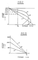
- FIG. 2 illustrates typical speed/torque characteristic curves A, B and C for so-called Class A, Class B and Class C induction motors. It is assumed for purposes of discussion that all three motors possess identical numbers of poles and design frequencies - e.g., four poles and 60 Hz - so that all motors have identical no-load speeds close to 1800 rpm. As load is applied, velocities of all three motors drop, initially substantially linearly, as a function of load toward rated torque for that motor at which the motor draws full load current. For purposes of comparison, it is assumed that all motors have identical rated torque T R . Beyond rated torque, speed continues to drop and load current increases toward stall (zero speed). Note that in each exemplary motor, stall current is greater than full load current.
- each motor has a slip speed which is inherent in the motor design, and which is equal to the difference between full load speed and the design no-load limit (1800 rpm in these examples).
- the slip speed at rated torque is 180 rpm (10%), corresponding to a slip frequency of 6 Hz.
- the slip speed and frequency are 360 rpm and 12 Hz, and for motor C 540 rpm and 18 Hz.
- FIG. 3 graphically illustrates the no-load to rated torque portion of curves A, B and C in FIG. 2 translated so as to intersect at rated torque T R and zero speed.
- Each curve in FIG. 3 thus exhibits a no-load speed corresponding to the slip speed at rated torque in FIG. 2.
- motor A is driven at 6 Hz, it will possess a no-load speed close to 180 rpm, and will deliver rated torque at full load current at stall.
- the motor may be driven indefinitely to deliver rated torque at stall.
- motor B will deliver rated torque at stall if driven at 12 Hz (with a corresponding no-load speed approaching 360 rpm), and motor C will deliver rated torque at stall if driven at 18 Hz (with a corresponding no-load speed approaching 540 rpm).
- drive voltage is selected empirically to deliver full load current at stall. Note that all of the motors in this example deliver the same rated torque T R at stall, and may be selected as a function of desired speeds during each portion of the drive cycle.
- first and second power supply means coupled to an induction motor for driving a load.
- Such first and second power supply means may comprise separate supplies as in FIG. 1, or separately selectable operating modes of a single supply.
- the first power supply means operate at the motor design frequency (e.g. 60 Hz) and possess an output voltage (e.g. 440 v) selected to deliver full load current at rated torque.
- the second power supply means operates at the slip frequency of the motor (e.g. 6 Hz) when driven at design frequency and voltage, and possesses an output voltage (e.g. 48 v) selected to deliver full load current at stall.
- a motor controller or the like selects between the first and second power supply means to achieve rapid initial motion at the load by coupling to the first supply, followed by slower load motion toward the final position and application of rated torque at stall.
- the disclosed implementation for actuating a workpiece clamp is exemplary but preferred.
Landscapes
- Engineering & Computer Science (AREA)
- Mechanical Engineering (AREA)
- Connection Of Motors, Electrical Generators, Mechanical Devices, And The Like (AREA)
- Jigs For Machine Tools (AREA)
- Control Of Multiple Motors (AREA)
Applications Claiming Priority (2)
| Application Number | Priority Date | Filing Date | Title |
|---|---|---|---|
| US06/918,899 US4812731A (en) | 1986-10-15 | 1986-10-15 | Clamp actuated by induction motor |
| US918899 | 1986-10-15 |
Publications (2)
| Publication Number | Publication Date |
|---|---|
| EP0264078A2 true EP0264078A2 (de) | 1988-04-20 |
| EP0264078A3 EP0264078A3 (de) | 1989-02-15 |
Family
ID=25441144
Family Applications (1)
| Application Number | Title | Priority Date | Filing Date |
|---|---|---|---|
| EP87114777A Withdrawn EP0264078A3 (de) | 1986-10-15 | 1987-10-09 | Durch Induktionsmotor betätigte Spannvorrichtung |
Country Status (3)
| Country | Link |
|---|---|
| US (1) | US4812731A (de) |
| EP (1) | EP0264078A3 (de) |
| JP (1) | JPS63185543A (de) |
Cited By (3)
| Publication number | Priority date | Publication date | Assignee | Title |
|---|---|---|---|---|
| EP0348802A3 (de) * | 1988-06-29 | 1991-11-13 | Eaton Corporation | Regler für eine elektrische Spannvorrichtung |
| US5139246A (en) * | 1989-11-08 | 1992-08-18 | Canon Kabushiki Kaisha | Work clamping apparatus |
| CN104289733A (zh) * | 2013-07-17 | 2015-01-21 | 通快机床两合公司 | 定位工件的夹紧装置、带夹紧装置的机床及工件定位方法 |
Families Citing this family (2)
| Publication number | Priority date | Publication date | Assignee | Title |
|---|---|---|---|---|
| US9815193B2 (en) * | 2011-06-27 | 2017-11-14 | Delaware Capital Formation, Inc. | Electric motor based holding control systems and methods |
| US11794309B2 (en) * | 2020-02-28 | 2023-10-24 | Hurco Companies, Inc. | Automated smart vise system |
Family Cites Families (14)
| Publication number | Priority date | Publication date | Assignee | Title |
|---|---|---|---|---|
| DE928097C (de) * | 1943-10-20 | 1955-05-23 | Friedrich Henze | Elektromotorisch spannbarer Schraubstock |
| GB920066A (en) * | 1958-05-09 | 1963-03-06 | Albert Honsberg Junior | An electro-mechanical chucking mechanism for clamping devices |
| GB927802A (en) * | 1960-05-06 | 1963-06-06 | Noble & Lund Ltd | Improvements in or relating to clamping or securing means |
| US3710218A (en) * | 1970-10-08 | 1973-01-09 | Micro Magnetic Ind Inc | Induction motor speed control |
| US3704879A (en) * | 1971-03-29 | 1972-12-05 | Kyoritsu Mfg Co Ltd | Electric vise |
| US3962614A (en) * | 1973-03-02 | 1976-06-08 | Litton Industrial Products, Inc. | Method for controlling the output condition of a self excited alternating current induction motor |
| US4311951A (en) * | 1979-04-24 | 1982-01-19 | General Electric Company | Apparatus and method for high slip operation of an AC electric motor at substantially zero rotation and substantially zero torque |
| JPS56103077A (en) * | 1980-01-21 | 1981-08-17 | Mitsubishi Electric Corp | Emergency driving device for elevator |
| US4559485A (en) * | 1981-08-31 | 1985-12-17 | Kollmorgen Technologies Corporation | Control systems for AC induction motors |
| JPS58119792A (ja) * | 1982-01-11 | 1983-07-16 | Hitachi Ltd | 誘導電動機の制御方法 |
| US4503371A (en) * | 1982-10-21 | 1985-03-05 | Tsudakoma Kogyo Kabushiki Kaisha | Mass driver circuit for weaving looms |
| DE3304851A1 (de) * | 1983-02-12 | 1984-08-16 | Reinhausen Maschf Scheubeck | Schaltanordnung fuer lastumschalter von stufenschaltern fuer stufentransformatoren |
| US4459533A (en) * | 1983-06-03 | 1984-07-10 | Beckman Instruments, Inc. | Variable slip drive system for induction motor |
| US4665323A (en) * | 1984-10-25 | 1987-05-12 | Zenith Electronics Corporation | Electronically switchable power source |
-
1986
- 1986-10-15 US US06/918,899 patent/US4812731A/en not_active Expired - Fee Related
-
1987
- 1987-10-09 EP EP87114777A patent/EP0264078A3/de not_active Withdrawn
- 1987-10-15 JP JP62258477A patent/JPS63185543A/ja active Pending
Cited By (8)
| Publication number | Priority date | Publication date | Assignee | Title |
|---|---|---|---|---|
| EP0348802A3 (de) * | 1988-06-29 | 1991-11-13 | Eaton Corporation | Regler für eine elektrische Spannvorrichtung |
| US5139246A (en) * | 1989-11-08 | 1992-08-18 | Canon Kabushiki Kaisha | Work clamping apparatus |
| US5293157A (en) * | 1989-11-08 | 1994-03-08 | Canon Kabushiki Kaisha | Work clamping method and apparatus using multi-positional finger members |
| CN104289733A (zh) * | 2013-07-17 | 2015-01-21 | 通快机床两合公司 | 定位工件的夹紧装置、带夹紧装置的机床及工件定位方法 |
| EP2826591A1 (de) * | 2013-07-17 | 2015-01-21 | TRUMPF Werkzeugmaschinen GmbH + Co. KG | Spannvorrichtung zum Positionieren von Werkstücken, Werkzeugmaschine mit einer derartigen Spannvorrichtung, Verfahren zum Positionieren von Werkstücken mittels einer derartigen Spannvorrichtung |
| US20150020372A1 (en) * | 2013-07-17 | 2015-01-22 | Trumpf Werkzeugmaschinen Gmbh + Co. Kg | Positioning Workpieces by Clamping Devices |
| US10016865B2 (en) * | 2013-07-17 | 2018-07-10 | Trumpf Werkzeugmaschinen Gmbh + Co. Kg | Positioning workpieces by clamping devices |
| CN104289733B (zh) * | 2013-07-17 | 2019-01-15 | 通快机床两合公司 | 定位工件的夹紧装置、带夹紧装置的机床及工件定位方法 |
Also Published As
| Publication number | Publication date |
|---|---|
| JPS63185543A (ja) | 1988-08-01 |
| US4812731A (en) | 1989-03-14 |
| EP0264078A3 (de) | 1989-02-15 |
Similar Documents
| Publication | Publication Date | Title |
|---|---|---|
| US5068587A (en) | Spindle drive control apparatus for a machine tool | |
| US4317578A (en) | Keyless chucking system | |
| GB1211456A (en) | Spindle orienting and drawbolt malfunction sensing machine tool control system | |
| WO1987005839A1 (fr) | Systeme de commande d'une operation de taraudage | |
| US4812731A (en) | Clamp actuated by induction motor | |
| US4379987A (en) | Spindle rotation control system | |
| US3731564A (en) | Machine tool | |
| AU606945B2 (en) | Method and device for braking a squirrel-cage motor | |
| KR0167825B1 (ko) | 트랜스퍼 반송장치의 비상퇴피장치 | |
| EP0401375B1 (de) | Regelungsverfahren des synchronisierten betriebs einer werkzeugmaschine | |
| EP0348802A2 (de) | Regler für eine elektrische Spannvorrichtung | |
| CN210677960U (zh) | 一种轴类自动加工设备 | |
| EP0442772B1 (de) | Roboter vom Direkt-Teach-In-Typ | |
| JP2807823B2 (ja) | 2主軸対向型cnc旋盤のワーク加工装置 | |
| KR930007539B1 (ko) | 공작기계의 주축구동장치 | |
| JPS5969815A (ja) | デイジタル位置決め制御装置 | |
| JPS5940963Y2 (ja) | ステツプ・フイ−ド工作機 | |
| JPH0283102A (ja) | 対向型2スピンドル旋盤の同期回転時のフリーラン方法 | |
| JPH01255015A (ja) | ロボットの制御装置 | |
| US2585216A (en) | Unitary mechanism for performing multiple simultaneous and successive operations | |
| JP3783253B2 (ja) | 複数ロボットの同調制御方法 | |
| JP4439063B2 (ja) | 旋盤へのバー材の供給方法 | |
| JPS6235907A (ja) | 工作機械の制御装置 | |
| CN87100434A (zh) | 液压伺服进给装置 | |
| JPS5940585B2 (ja) | スピンドル位置制御機能を有する工作機械 |
Legal Events
| Date | Code | Title | Description |
|---|---|---|---|
| PUAI | Public reference made under article 153(3) epc to a published international application that has entered the european phase |
Free format text: ORIGINAL CODE: 0009012 |
|
| AK | Designated contracting states |
Kind code of ref document: A2 Designated state(s): DE FR GB |
|
| PUAL | Search report despatched |
Free format text: ORIGINAL CODE: 0009013 |
|
| AK | Designated contracting states |
Kind code of ref document: A3 Designated state(s): DE FR GB |
|
| STAA | Information on the status of an ep patent application or granted ep patent |
Free format text: STATUS: THE APPLICATION IS DEEMED TO BE WITHDRAWN |
|
| 18D | Application deemed to be withdrawn |
Effective date: 19890816 |