EP0264172A2 - Chariot élévateur et son procédé de fabrication - Google Patents
Chariot élévateur et son procédé de fabrication Download PDFInfo
- Publication number
- EP0264172A2 EP0264172A2 EP87306117A EP87306117A EP0264172A2 EP 0264172 A2 EP0264172 A2 EP 0264172A2 EP 87306117 A EP87306117 A EP 87306117A EP 87306117 A EP87306117 A EP 87306117A EP 0264172 A2 EP0264172 A2 EP 0264172A2
- Authority
- EP
- European Patent Office
- Prior art keywords
- battery box
- assembly
- main frame
- components
- truck
- Prior art date
- Legal status (The legal status is an assumption and is not a legal conclusion. Google has not performed a legal analysis and makes no representation as to the accuracy of the status listed.)
- Withdrawn
Links
Images


Classifications
-
- B—PERFORMING OPERATIONS; TRANSPORTING
- B66—HOISTING; LIFTING; HAULING
- B66F—HOISTING, LIFTING, HAULING OR PUSHING, NOT OTHERWISE PROVIDED FOR, e.g. DEVICES WHICH APPLY A LIFTING OR PUSHING FORCE DIRECTLY TO THE SURFACE OF A LOAD
- B66F9/00—Devices for lifting or lowering bulky or heavy goods for loading or unloading purposes
- B66F9/06—Devices for lifting or lowering bulky or heavy goods for loading or unloading purposes movable, with their loads, on wheels or the like, e.g. fork-lift trucks
- B66F9/075—Constructional features or details
- B66F9/07554—Counterweights
-
- B—PERFORMING OPERATIONS; TRANSPORTING
- B66—HOISTING; LIFTING; HAULING
- B66F—HOISTING, LIFTING, HAULING OR PUSHING, NOT OTHERWISE PROVIDED FOR, e.g. DEVICES WHICH APPLY A LIFTING OR PUSHING FORCE DIRECTLY TO THE SURFACE OF A LOAD
- B66F9/00—Devices for lifting or lowering bulky or heavy goods for loading or unloading purposes
- B66F9/06—Devices for lifting or lowering bulky or heavy goods for loading or unloading purposes movable, with their loads, on wheels or the like, e.g. fork-lift trucks
- B66F9/075—Constructional features or details
- B66F9/07513—Details concerning the chassis
- B66F9/07518—Fuel or oil tank arrangements
-
- B—PERFORMING OPERATIONS; TRANSPORTING
- B66—HOISTING; LIFTING; HAULING
- B66F—HOISTING, LIFTING, HAULING OR PUSHING, NOT OTHERWISE PROVIDED FOR, e.g. DEVICES WHICH APPLY A LIFTING OR PUSHING FORCE DIRECTLY TO THE SURFACE OF A LOAD
- B66F9/00—Devices for lifting or lowering bulky or heavy goods for loading or unloading purposes
- B66F9/06—Devices for lifting or lowering bulky or heavy goods for loading or unloading purposes movable, with their loads, on wheels or the like, e.g. fork-lift trucks
- B66F9/075—Constructional features or details
- B66F9/07513—Details concerning the chassis
- B66F9/07531—Battery compartments
-
- B—PERFORMING OPERATIONS; TRANSPORTING
- B66—HOISTING; LIFTING; HAULING
- B66F—HOISTING, LIFTING, HAULING OR PUSHING, NOT OTHERWISE PROVIDED FOR, e.g. DEVICES WHICH APPLY A LIFTING OR PUSHING FORCE DIRECTLY TO THE SURFACE OF A LOAD
- B66F9/00—Devices for lifting or lowering bulky or heavy goods for loading or unloading purposes
- B66F9/06—Devices for lifting or lowering bulky or heavy goods for loading or unloading purposes movable, with their loads, on wheels or the like, e.g. fork-lift trucks
- B66F9/075—Constructional features or details
- B66F9/07545—Overhead guards
-
- B—PERFORMING OPERATIONS; TRANSPORTING
- B60—VEHICLES IN GENERAL
- B60G—VEHICLE SUSPENSION ARRANGEMENTS
- B60G2300/00—Indexing codes relating to the type of vehicle
- B60G2300/02—Trucks; Load vehicles
- B60G2300/022—Fork lift trucks, Clark
-
- Y—GENERAL TAGGING OF NEW TECHNOLOGICAL DEVELOPMENTS; GENERAL TAGGING OF CROSS-SECTIONAL TECHNOLOGIES SPANNING OVER SEVERAL SECTIONS OF THE IPC; TECHNICAL SUBJECTS COVERED BY FORMER USPC CROSS-REFERENCE ART COLLECTIONS [XRACs] AND DIGESTS
- Y10—TECHNICAL SUBJECTS COVERED BY FORMER USPC
- Y10T—TECHNICAL SUBJECTS COVERED BY FORMER US CLASSIFICATION
- Y10T29/00—Metal working
- Y10T29/49—Method of mechanical manufacture
- Y10T29/49826—Assembling or joining
- Y10T29/49828—Progressively advancing of work assembly station or assembled portion of work
- Y10T29/49829—Advancing work to successive stations [i.e., assembly line]
-
- Y—GENERAL TAGGING OF NEW TECHNOLOGICAL DEVELOPMENTS; GENERAL TAGGING OF CROSS-SECTIONAL TECHNOLOGIES SPANNING OVER SEVERAL SECTIONS OF THE IPC; TECHNICAL SUBJECTS COVERED BY FORMER USPC CROSS-REFERENCE ART COLLECTIONS [XRACs] AND DIGESTS
- Y10—TECHNICAL SUBJECTS COVERED BY FORMER USPC
- Y10T—TECHNICAL SUBJECTS COVERED BY FORMER US CLASSIFICATION
- Y10T29/00—Metal working
- Y10T29/49—Method of mechanical manufacture
- Y10T29/49826—Assembling or joining
- Y10T29/49906—Metal deforming with nonmetallic bonding
Definitions
- This invention relates to lift trucks and to a method of manufacturing same.
- one or more components are mounted in and on the all welded frame at each of many stations along the assembly line and interconnected as required as by electrical cables and hydraulic conduits to effect an operable vehicle.
- the invention is particularly adapted for use with four-wheel electric sit-down rider lift trucks.
- the present invention provides a method of manufacturing electric lift trucks comprising the steps of mounting on the main frame of the truck a plurality of components, including a traction drive unit assembly at one or more assembly stations, mounting on a battery box means adapted to receive a traction battery a plurality of components at one or more assembly stations, and mounting in the main frame said pre-assembled battery box means.
- the present invention also provides a lift truck comprising a main frame having mounted thereon a traction drive unit assembly, a battery box means adapted to receive a traction drive battery adapted to be secured to the main frame and detachable therefrom as a unit, said battery box means providing traction drive battery retainer means, said battery box means when in rigid connected relationship to the main frame functioning as a structural means of said main frame, and a plurality of components assembled on the battery box means the battery box means when detached from the main frame providing ready access for servicing of those components mounted on the battery box means as well as ready access for servicing components mounted in the main frame.
- the mounted battery box doubles both as a structural assembly of the truck frame and as a battery retainer, and on which is pre-assembled a plurality of truck components and controls. It is secured to the truck frame such as by bolts to hold it in rigid relationship thereto, except when servicing is required in the after-market.
- the battery box assembly may be readily dismounted from the truck frame for easy access and servicing of the components and controls mounted thereon and on the main frame, as well as being adaptable for receiving battery box assemblies of different sizes on the same main frame assembly for different truck operating requirements.
- two assembly stations are requred, for example, one for main frame assembly and another for battery box assembly, which assemblies may be combined at the main frame assembly station.
- a lift truck having a main frame and a body construction 10 mounted on pairs of traction and steer wheels 12 and 14, respectively, which together with the drive train comprises a chassis 15.
- An upright and fork carriage assembly 16 is mounted at the forward end of the chassis, a sub-assembly battery box and controls assembly 18 is mounted in the central section of the lift truck, and an overhead guard asembly 20, operator's steering wheel and pylon 22, and a rearwardly pivotable box-like hood device 24 having mounted thereon an operator's set 25 are mounted as shown.
- a drive or traction battery 26 is adapted to be installed in the battery box and a counterweight assembly 28 is mounted from the rear of the truck. It will be unerstood that battery 26 also provides a source of energy for all electrically operated components, such as the lift and steer pump motors, in addition to providing the energy source for the electric drive motor of the truck.
- the main frame 10 shown best in Fig. 9 is an all-welded construction which, when combined with the drive and steer wheels and associated drive line components, certain of which are shown in Figs. 6 and 7, comprises chassis 15 of the lift truck.
- the frame comprises an all-welded configured construction as illustrated including side rail box frame members 30 welded to which are a pair of inwardly projecting configured top plate portions 31, a recessed drop box 32, which also serves as a main structural transverse frame member of generally inverted triangular shape in projection, welded at its upper leg edges to plates 31 and adapted to support in known manner from an apex portion 33 one side of a steer axle assembly 34, and upstanding brackets 36 forming bolt openings 38 which together with bolt openings 39 in plates 31 are adapted to secure the battery box assembly 18 at registrable bolt openings.
- One or both sides of box frame sections 30 may be sealed to provide hydraulic oil sumps for the hydraulic system which supplies various components such as the lift and tilt cylinders and steer pump.
- a unitary drive axle and traction motor is supported rigidly from a pair of spaced frame plates 41. Wells for the drive and steer wheels are formed as shown.
- a transverse structural rail 42 at the front of the frame is secured to the upper fender sections of the traction wheel wells, secured to and extending upwardly from which is a known configuration of a front protective plate portion 44.
- Other parts of frame 10 are as illustrated in Fig. 9.
- the drive axle assembly is of well known construction having rigidly mounted thereto an electric traction drive motor 50, the complete assembly of which is mounted in known manner to the front of the truck frame at the arcuate sections of frame plates 41, the drive motor being cantilevered to extend longitudinally and rearwardly of the drive axle in the open center section of the main frame (Fig. 7).
- Upright assembly 16 is bearing mounted in known manner from the drive axle arms and is connected to the frame by tilt cylinders which are anchored to the frame at pairs of pivot connection openings 52.
- the battery box 18 (Fig. 10) comprises a three-sided welded construction having upstanding forward and rearward transverse plate members 60 and 62 forming with a bottom connecting plate 64 a side-to-side open compartment for receiving the drive or traction battery 26 (Fig. 1), a plurality of suitable openings in plates 60 and 64, as shown, being adapted to register with openings 38 and 39 in the main frame for rigidly connecting the battery box with the frame, as by volts, and thereby forming further rigid transverse structural frame members with the main frame.
- a counterweight support bracket 66 is welded to a rearwardly extending plate portion 68, in turn welded to plate 62 and to a pair of spaced vertical plates 70 forming with plate 68 a recessed area to the rear of plate 62 for receiving an assembly of SCR controls 72.
- Channel 74 at the time of assembly of the battery box to the main frame is received in the main frame opening rearwardly of the traction motor 50 and extends rearwardly through the recess formed by drop box 32.
- a pair of transversely spaced opening 76 in plate 62 combine with an opening 78 in bracket 66 to support the upper and lower counterweight assembly 28 at the time of assembly of the counterweight with the battery box assembly subsequent to the mounting of the latter on the main frame.
- An interior open section in the counterweight not shown, houses and protects the exposed portion of the SCR control. Although the latter construction is preferred it will be understood that alternatively the SCR control can be mounted and housed in the interior open section of the counterweight.
- a plurality of truck operating components mounted at the forward end of the battery box to plates 60 and 64 are a plurality of truck operating components, best shown in Figs 4 and 5.
- a main hydraulic valve assembly 80 connected to which are a plurality of flexible hydraulic conduits for coupling connection with the main lift cylinder of upright 16, a pair of upright tilt cylinders, not shown, and the lift pump of a lift pump and motor assembly 82 which is mounted from and transversely of the lower side of plate 64.
- the lift pump and motor assembly at the time of assembly of the battery box with the main frame nests transversely in the space between frame rails 30 and in a space provided between the rear end of traction motor 50 and the vertical plate of recess drop box 32.
- valve control assembly 84 Mounted on top of valve assembly 80 and secured thereto is an operator's valve control assembly 84 having valve levers 86 for controlling the operation of the pump and motor assembly 82, and the upright lift and tilt cylinders. Electric lines 86 connect the lever assembly 84 to the lift motor via a main wire harness for operating the lift pump and motor assembly.
- a steer pump and motor assembly 90 is suitably mounted at the lower front central portion of plate 60, a plurality of flexible conduits connecting the pump portion thereof to the power steering cylinder of wheels 14 via channel 74, and the motor portion thereof to the steering control in pylon 48 for drive control by the steer wheel subsequent to mounting the battery box on the main frame.
- a return line oil filter 92 is supported forwardly of the pump motor assembly 90 from a forward extending bracket 94 which is bolted to plate 60.
- Power cables 96 being connected to a battery connector 98 on plate 60 at the one ends, extend through the channel guide 74 to connect to the SCR control at the other ends. With the battery installed battery cables, not shown, are adapted to be connected to the traction motor.
- the lift motor and pump assembly 82 is supported from a bracket 100 which is connected to bottom plate 64 (Fig. 6).
- An exemplary assembly process in the manufacture of lift trucks utilizing the present invention may be as follows:
- a main frame structure having been previously welded up is first located at one end of an assembly line at the first station of which the drive motor and axle assembly, as well as electrical cables and harnesses therefor, are assembled in the forward end of the frame.
- This assembly includes traction motor 50, a drive axle, and related parts.
- a plurality of additional components are assembled on or in the main frame including power steering components and steer wheels, the drive wheels, operator pedal controls, steering wheel and drive controls in the pylon 48, upright tilt cylinders, and the like.
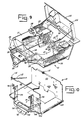
- Brackets 110 (Fig. 11) are adapted to secure the hood and seat assembly to the rear legs of the overhead guard.
- a gas charged cylinder 112 (Fig. 10) is connected by a bracket 114 to the one side of plate 62 and is adapted to be connected at the rod end to a bracket, not shown, of the horizontal under surface of the hood.
- a hood latch device of known design comprises a stud bolt 116 secured suitably to the upper edge portion of plate 60 (Fig.
- U.S. Patent 3,976,157 discloses a hood latch device which is suitable in principle to be used with this invention.
- Gas cylinder 112 is preferably precharged so that when connected to the hood it holds the hood in a slightly raised position, when the hood is latched to stud bolt 116 by pushing it down against the gas cylinder it thus becomes a rigid sub-assembly of the battery box assembly and functions as an upper frame portion thereof.
- the gas cylinder assists the operator by reducing the effort required both in raising and lowering the hood.
- Figure 11 illustrates somewhat schematically the pre-assembly of the counterweight, hood and seat assembly and overhead guard on the battery box assembly.
- battery box size may be altered to suit requirements. For example, customers may specify battery box size desired from the battery power requirements of different applications whereby battery box specifications may be altered to a variety of custom requirements while utilizing the same main frame.
- the invention significantly reduces the cost and time and space requirements for lift truck assembly. It further has the important after-market advantage of providing easy access to most major truck components by providing for the ready removal, if required, of the battery box and assembled components so as to "open up" the main frame and its assembled components while at the same time providing for removal of the battery box to a convenient location for servicing any components assembled thereon. Thus, easy access for the subsequent servicing and replacement of various components as may be required is provided.
Landscapes
- Engineering & Computer Science (AREA)
- Transportation (AREA)
- Structural Engineering (AREA)
- Civil Engineering (AREA)
- Life Sciences & Earth Sciences (AREA)
- Geology (AREA)
- Mechanical Engineering (AREA)
- Arrangement Or Mounting Of Propulsion Units For Vehicles (AREA)
- Automobile Manufacture Line, Endless Track Vehicle, Trailer (AREA)
- Forklifts And Lifting Vehicles (AREA)
- Battery Mounting, Suspending (AREA)
Applications Claiming Priority (2)
| Application Number | Priority Date | Filing Date | Title |
|---|---|---|---|
| US918957 | 1986-10-15 | ||
| US06/918,957 US4811473A (en) | 1986-01-13 | 1986-10-15 | Method of manufacturing electric lift trucks |
Publications (2)
| Publication Number | Publication Date |
|---|---|
| EP0264172A2 true EP0264172A2 (fr) | 1988-04-20 |
| EP0264172A3 EP0264172A3 (fr) | 1990-01-17 |
Family
ID=25441227
Family Applications (1)
| Application Number | Title | Priority Date | Filing Date |
|---|---|---|---|
| EP87306117A Withdrawn EP0264172A3 (fr) | 1986-10-15 | 1987-07-10 | Chariot élévateur et son procédé de fabrication |
Country Status (5)
| Country | Link |
|---|---|
| US (1) | US4811473A (fr) |
| EP (1) | EP0264172A3 (fr) |
| JP (1) | JPS63103781A (fr) |
| KR (1) | KR880005024A (fr) |
| CA (1) | CA1282377C (fr) |
Cited By (4)
| Publication number | Priority date | Publication date | Assignee | Title |
|---|---|---|---|---|
| FR2681304A1 (fr) * | 1991-09-14 | 1993-03-19 | Linde Ag | Chariot elevateur a fourche, constitue de deux groupes preassembles. |
| WO1993008064A1 (fr) * | 1991-10-24 | 1993-04-29 | Angel Ivanov Veninski | Chassis pour vehicule de manutention et materiel de manutention le comprenant |
| WO2006016233A1 (fr) * | 2004-08-05 | 2006-02-16 | V. Mariotti S.R.L. | Corps standard pour camion à fourche élévateur électrique et processus de fabrication de celui-ci |
| US20130259626A1 (en) * | 2012-04-03 | 2013-10-03 | Harnischfeger Technologies, Inc. | Counterweight system for an industrial machine |
Families Citing this family (9)
| Publication number | Priority date | Publication date | Assignee | Title |
|---|---|---|---|---|
| JPH0780466B2 (ja) * | 1987-12-25 | 1995-08-30 | 日産自動車株式会社 | 産業車両の車体構造 |
| US5836412A (en) * | 1993-11-22 | 1998-11-17 | Textron, Inc. | Method of assembling a golf car |
| US5437939A (en) * | 1994-01-06 | 1995-08-01 | Gnb Industrial Battery Company | Sealed lead-acid battery tray assemblies and motive power vehicles using such battery tray assemblies |
| DE10221312B4 (de) * | 2002-05-14 | 2006-04-06 | Jungheinrich Ag | Rahmen für das Antriebsteil eines Flurförderzeugs, insbesondere eines Hubwagens |
| DE102007052976A1 (de) * | 2007-01-27 | 2008-07-31 | Linde Material Handling Gmbh | Flurförderzeug mit einem zur Aufnahme eines Batterieblocks ausgebildeten Tragabschnitt und einem schwenkbaren Längsträger |
| US8108989B2 (en) | 2007-06-28 | 2012-02-07 | Crown Equipment Corporation | Manufacturing cell and elements of the cell |
| DE102007037098A1 (de) * | 2007-08-07 | 2009-02-12 | Jungheinrich Ag | Verfahren und Bausatzgruppe für die Herstellung von Unterbauten von Flurförderzeugen |
| CN112139696B (zh) * | 2020-09-28 | 2021-12-07 | 杭州叉车钣焊有限公司 | 一种内燃叉车车架自动化生产线 |
| CN112792359B (zh) * | 2020-12-24 | 2022-05-10 | 江苏恒力组合机床有限公司 | 一种桥壳两端车轴数控加工机床 |
Family Cites Families (10)
| Publication number | Priority date | Publication date | Assignee | Title |
|---|---|---|---|---|
| US2757447A (en) * | 1951-12-11 | 1956-08-07 | Daimler Benz Ag | Method for assembling motor vehicles |
| US2779092A (en) * | 1951-12-26 | 1957-01-29 | Progressive Welder Sales Compa | Method and apparatus for making vehicle bodies |
| FR1259133A (fr) * | 1960-05-18 | 1961-04-21 | Esslingen Maschf | Chariot élévateur |
| US3367441A (en) * | 1966-04-01 | 1968-02-06 | Allis Chalmers Mfg Co | Unitized battery case and counterweight |
| US3497090A (en) * | 1968-04-03 | 1970-02-24 | Allis Chalmers Mfg Co | Combined battery case and counterweight |
| US3721353A (en) * | 1970-12-14 | 1973-03-20 | Clark Equipment Co | Combined battery case,counterweight and overhead guard |
| US3756350A (en) * | 1971-03-01 | 1973-09-04 | Hyster Co | Materials handling truck |
| SE398468B (sv) * | 1971-12-23 | 1977-12-27 | Daimler Benz Ag | Anordning for uppberande av ett batteritrag i chassiet av ett batteridrivet fordon |
| JPS6015509B2 (ja) * | 1979-05-29 | 1985-04-19 | 日産自動車株式会社 | フオ−クリフトのリアフレ−ム構造 |
| US4312418A (en) * | 1980-03-31 | 1982-01-26 | Clark Equipment Company | Pivoted valve and hood for lift truck |
-
1986
- 1986-10-15 US US06/918,957 patent/US4811473A/en not_active Expired - Fee Related
-
1987
- 1987-06-30 CA CA000541016A patent/CA1282377C/fr not_active Expired - Lifetime
- 1987-07-10 EP EP87306117A patent/EP0264172A3/fr not_active Withdrawn
- 1987-07-14 KR KR1019870007565A patent/KR880005024A/ko not_active Ceased
- 1987-07-14 JP JP62174052A patent/JPS63103781A/ja active Pending
Cited By (6)
| Publication number | Priority date | Publication date | Assignee | Title |
|---|---|---|---|---|
| FR2681304A1 (fr) * | 1991-09-14 | 1993-03-19 | Linde Ag | Chariot elevateur a fourche, constitue de deux groupes preassembles. |
| WO1993008064A1 (fr) * | 1991-10-24 | 1993-04-29 | Angel Ivanov Veninski | Chassis pour vehicule de manutention et materiel de manutention le comprenant |
| WO2006016233A1 (fr) * | 2004-08-05 | 2006-02-16 | V. Mariotti S.R.L. | Corps standard pour camion à fourche élévateur électrique et processus de fabrication de celui-ci |
| US20130259626A1 (en) * | 2012-04-03 | 2013-10-03 | Harnischfeger Technologies, Inc. | Counterweight system for an industrial machine |
| US9702114B2 (en) * | 2012-04-03 | 2017-07-11 | Harnischfeger Technologies, Inc. | Counterweight system for an industrial machine |
| US10106956B2 (en) | 2012-04-03 | 2018-10-23 | Joy Global Surface Mining Inc | Counterweight system for an industrial machine |
Also Published As
| Publication number | Publication date |
|---|---|
| EP0264172A3 (fr) | 1990-01-17 |
| JPS63103781A (ja) | 1988-05-09 |
| US4811473A (en) | 1989-03-14 |
| CA1282377C (fr) | 1991-04-02 |
| KR880005024A (ko) | 1988-06-27 |
Similar Documents
| Publication | Publication Date | Title |
|---|---|---|
| EP0231642B1 (fr) | Chariot élévateur et procédé pour sa fabrication | |
| US4834424A (en) | Lift truck | |
| EP0264172A2 (fr) | Chariot élévateur et son procédé de fabrication | |
| US5918692A (en) | Small-sized vehicle | |
| US8047557B2 (en) | Vehicle body frame structure | |
| US11548559B2 (en) | Vehicle structure | |
| US6397965B1 (en) | Engine configuration for mass transit vehicle | |
| CN107054039A (zh) | 四轮车辆 | |
| CN107031718A (zh) | 四轮车辆 | |
| EP3738807B1 (fr) | Faux cadre de voiture électrique | |
| JP5822280B2 (ja) | 自動車の組立て方法 | |
| JP3620242B2 (ja) | 電気自動車用バッテリ搭載構造 | |
| TW472012B (en) | Scooter type vehicle | |
| US3378094A (en) | Motor vehicle | |
| US4692086A (en) | Load handling vehicle | |
| JP3950274B2 (ja) | 車輛のエンジン脱着装置 | |
| CN222247166U (zh) | 全地形车 | |
| US20240157775A1 (en) | Work Vehicle | |
| US20240157818A1 (en) | Work Vehicle | |
| JP7655288B2 (ja) | トレーラ | |
| JPS5915739Y2 (ja) | 車輛のフエンダ−取付構造 | |
| JPS62175271A (ja) | リフトトラツクとその製造方法 | |
| EP3480036B1 (fr) | Système de suspension de roues d'un véhicule | |
| WO2024070345A1 (fr) | Camion à benne basculante | |
| CN120503879A (zh) | 牵引车底盘和牵引车 |
Legal Events
| Date | Code | Title | Description |
|---|---|---|---|
| PUAI | Public reference made under article 153(3) epc to a published international application that has entered the european phase |
Free format text: ORIGINAL CODE: 0009012 |
|
| AK | Designated contracting states |
Kind code of ref document: A2 Designated state(s): DE ES FR GB GR |
|
| PUAL | Search report despatched |
Free format text: ORIGINAL CODE: 0009013 |
|
| AK | Designated contracting states |
Kind code of ref document: A3 Designated state(s): DE ES FR GB GR |
|
| STAA | Information on the status of an ep patent application or granted ep patent |
Free format text: STATUS: THE APPLICATION HAS BEEN WITHDRAWN |
|
| 17P | Request for examination filed |
Effective date: 19900702 |
|
| 18W | Application withdrawn |
Withdrawal date: 19900707 |
|
| RIN1 | Information on inventor provided before grant (corrected) |
Inventor name: LINK, DAVID HERBERT |