EP0264370B1 - Capteur de pression - Google Patents
Capteur de pression Download PDFInfo
- Publication number
- EP0264370B1 EP0264370B1 EP86903217A EP86903217A EP0264370B1 EP 0264370 B1 EP0264370 B1 EP 0264370B1 EP 86903217 A EP86903217 A EP 86903217A EP 86903217 A EP86903217 A EP 86903217A EP 0264370 B1 EP0264370 B1 EP 0264370B1
- Authority
- EP
- European Patent Office
- Prior art keywords
- pressure sensor
- substrate
- housing
- sensor according
- pressure
- Prior art date
- Legal status (The legal status is an assumption and is not a legal conclusion. Google has not performed a legal analysis and makes no representation as to the accuracy of the status listed.)
- Expired - Lifetime
Links
- 239000000758 substrate Substances 0.000 claims description 33
- 239000004020 conductor Substances 0.000 claims description 12
- 239000011324 bead Substances 0.000 claims description 7
- 150000001875 compounds Chemical class 0.000 claims description 4
- 230000001681 protective effect Effects 0.000 claims description 4
- 229910000831 Steel Inorganic materials 0.000 claims 1
- 239000010959 steel Substances 0.000 claims 1
- 230000002093 peripheral effect Effects 0.000 abstract 1
- 238000005259 measurement Methods 0.000 description 10
- DOSMHBDKKKMIEF-UHFFFAOYSA-N 2-[3-(diethylamino)-6-diethylazaniumylidenexanthen-9-yl]-5-[3-[3-[4-(1-methylindol-3-yl)-2,5-dioxopyrrol-3-yl]indol-1-yl]propylsulfamoyl]benzenesulfonate Chemical compound C1=CC(=[N+](CC)CC)C=C2OC3=CC(N(CC)CC)=CC=C3C(C=3C(=CC(=CC=3)S(=O)(=O)NCCCN3C4=CC=CC=C4C(C=4C(NC(=O)C=4C=4C5=CC=CC=C5N(C)C=4)=O)=C3)S([O-])(=O)=O)=C21 DOSMHBDKKKMIEF-UHFFFAOYSA-N 0.000 description 4
- 230000005540 biological transmission Effects 0.000 description 4
- 229910001220 stainless steel Inorganic materials 0.000 description 4
- 239000010935 stainless steel Substances 0.000 description 4
- 230000001419 dependent effect Effects 0.000 description 3
- 238000001514 detection method Methods 0.000 description 3
- 239000003822 epoxy resin Substances 0.000 description 3
- 229920000647 polyepoxide Polymers 0.000 description 3
- 238000009530 blood pressure measurement Methods 0.000 description 2
- 239000000919 ceramic Substances 0.000 description 2
- 239000013078 crystal Substances 0.000 description 2
- 238000013461 design Methods 0.000 description 2
- 229920001296 polysiloxane Polymers 0.000 description 2
- 238000004382 potting Methods 0.000 description 2
- 230000002159 abnormal effect Effects 0.000 description 1
- 230000001154 acute effect Effects 0.000 description 1
- 238000005266 casting Methods 0.000 description 1
- 230000006835 compression Effects 0.000 description 1
- 238000007906 compression Methods 0.000 description 1
- 238000010276 construction Methods 0.000 description 1
- 238000010292 electrical insulation Methods 0.000 description 1
- 238000005516 engineering process Methods 0.000 description 1
- 230000002349 favourable effect Effects 0.000 description 1
- 238000009434 installation Methods 0.000 description 1
- 239000011810 insulating material Substances 0.000 description 1
- 238000000034 method Methods 0.000 description 1
- 238000012544 monitoring process Methods 0.000 description 1
- 230000010355 oscillation Effects 0.000 description 1
- 238000012545 processing Methods 0.000 description 1
- 230000001105 regulatory effect Effects 0.000 description 1
- 238000007789 sealing Methods 0.000 description 1
- 239000004065 semiconductor Substances 0.000 description 1
- 238000005476 soldering Methods 0.000 description 1
- 239000000725 suspension Substances 0.000 description 1
- 238000003466 welding Methods 0.000 description 1
Images


Classifications
-
- B—PERFORMING OPERATIONS; TRANSPORTING
- B60—VEHICLES IN GENERAL
- B60C—VEHICLE TYRES; TYRE INFLATION; TYRE CHANGING; CONNECTING VALVES TO INFLATABLE ELASTIC BODIES IN GENERAL; DEVICES OR ARRANGEMENTS RELATED TO TYRES
- B60C23/00—Devices for measuring, signalling, controlling, or distributing tyre pressure or temperature, specially adapted for mounting on vehicles; Arrangement of tyre inflating devices on vehicles, e.g. of pumps or of tanks; Tyre cooling arrangements
- B60C23/02—Signalling devices actuated by tyre pressure
- B60C23/04—Signalling devices actuated by tyre pressure mounted on the wheel or tyre
- B60C23/0408—Signalling devices actuated by tyre pressure mounted on the wheel or tyre transmitting the signals by non-mechanical means from the wheel or tyre to a vehicle body mounted receiver
- B60C23/0422—Signalling devices actuated by tyre pressure mounted on the wheel or tyre transmitting the signals by non-mechanical means from the wheel or tyre to a vehicle body mounted receiver characterised by the type of signal transmission means
- B60C23/0427—Near field transmission with inductive or capacitive coupling means
- B60C23/043—Near field transmission with inductive or capacitive coupling means using transformer type signal transducers, e.g. rotary transformers
-
- B—PERFORMING OPERATIONS; TRANSPORTING
- B60—VEHICLES IN GENERAL
- B60C—VEHICLE TYRES; TYRE INFLATION; TYRE CHANGING; CONNECTING VALVES TO INFLATABLE ELASTIC BODIES IN GENERAL; DEVICES OR ARRANGEMENTS RELATED TO TYRES
- B60C23/00—Devices for measuring, signalling, controlling, or distributing tyre pressure or temperature, specially adapted for mounting on vehicles; Arrangement of tyre inflating devices on vehicles, e.g. of pumps or of tanks; Tyre cooling arrangements
- B60C23/02—Signalling devices actuated by tyre pressure
- B60C23/04—Signalling devices actuated by tyre pressure mounted on the wheel or tyre
- B60C23/0491—Constructional details of means for attaching the control device
- B60C23/0498—Constructional details of means for attaching the control device for rim attachments
Definitions
- the invention is directed to a pressure sensor according to the preamble of claim 1 (see e.g. DE-A-2 936 213).
- Such a pressure sensor is used to detect the air pressure inside what are known as tubeless tires of motor vehicles.
- the air pressure in such tires is of considerable importance for the road holding of the vehicle as well as for the life of the tires. Accordingly, in the context of the measurement of important motor vehicle parameters, it also appears desirable to record and monitor this tire pressure as precisely as possible.
- the problem with obtaining the corresponding measured values lies in the fact that tires are subject to considerable mechanical loads during operation of the motor vehicle as well as during assembly and disassembly, which can lead to damage to the sensors, particularly when sensors are desirable. Furthermore, there is the problem that the centrifugal forces that occur can distort measured values from pressure sensors.
- FR-A 2 241 420 US-A 3 249 916, FR-A 2 177 947 and FR-A 2 404 375 are pressure sensors for monitoring the tire pressure on vehicles known in which a switching element is provided in a wheel-fixed resonant circuit, which is opened or closed depending on the tire pressure. The switching state of the switching element is sensed by a wirelessly coupled high-frequency oscillation on the resonant circuit. Furthermore, it is known from FR-A 2 211 701 to hold a permanent magnet in an outer or inner position of a pressure sensor in the wheel rim depending on the air pressure in the tire. The position of the permanent magnet is queried by an electrical coil on the wheel suspension when the pressure sensor is turned past.
- These known solutions also have the disadvantage that they are very insensitive and only indicate that the air pressure in the tire falls below a permissible value. A temperature-dependent change in the permissible pressure value cannot be taken into account.
- the invention has for its object to design a pressure sensor of the type mentioned in such a way that a simple and reliable mounting of the entire pressure sensor on the rim is made possible, wherein the sensor elements of the pressure sensor are arranged in this tension-free and protected against damage and with the pressure and the temperature of the air in the tire should be applied.
- a particularly stress-free fastening of the substrate of the sensor elements is achieved by the potting provided according to claim 2, since the epoxy resin used for this purpose cures largely without generating stress and its temperature-dependent expansion is adapted to the substrate.
- This fastening technology therefore offers considerable advantages over mechanical fastenings such as screws or clamps, but a comparably high strength is achieved.
- soldering lugs formed by the holes provided according to claim 5 enable simple and firm reception of the connecting conductors and their contacting with the conductor tracks provided according to claim 6.
- the potting provided according to claim 7 ensures high mechanical strength and good electrical insulation, the construction being particularly simple when combined with the attachment of the substrate to the housing according to claim 8.
- the sensor elements By arranging the sensor elements on the back of the substrate according to claim 9, they are not pulled away from the substrate by possible centrifugal forces, but are pressed against them. Good heat conduction of the substrate keeps the sensor elements at the temperature of the air in the tire.
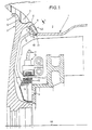
- FIG. 1 shows a section of a rim 1, which has a drum-like base body 2, to which a circumferential bead 3 (of which only one is shown in FIG. 1) adjoins the outer edges.
- Each bead 3 comprises a radially outer first section 4 and a radially inner second section 5.
- the wall 7 of a tire 8 shown only in sections abuts against the inner side 6 of the radially outer section 4.
- the radially inner section 5 of the bead 3 is provided with a bore 9 for receiving the pressure sensor 10.
- a commercially available connecting line opens into the housing 11 of the pressure sensor 10. It consists of a stainless steel tube 12, in which a plurality of connecting conductors 13 are guided separately from one another in an insulating compound, which connect the pressure sensor 10 to a data transmission device 15, which is shown only schematically and is connected to the rim by means of a screw 14.
- This data transmission device 15 is assigned a vehicle-mounted, stationary data receiver device 16, which forwards the electrical measured values emitted by the pressure sensor 10 to a central processing and display device via a line 17 which is shown schematically.
- This data transmission can be accomplished using techniques known per se. A related possibility is e.g. in U.S. Patent 4,237,728 which was mentioned at the outset.
- FIG. 2 shows the pressure sensor 10 according to the invention, which is shown only schematically in FIG. 1, in detail.
- the stainless steel tube 12 is welded at the upper end to the stainless steel housing 11 by means of the weld seam 18 by laser.
- the housing 11 has a circumferential annular groove 19 on the outside. During assembly, the housing 11 is inserted from the outside through the bore 9 in the section 5 of the rim 1, whereupon annular half-disks 24 are inserted into the annular groove 19 from both sides, which are secured radially outward through a blind hole 20 in the section 5 and come to lie in this so that the top is flush with the outer surface of the rim portion 5.
- the housing 11 has a threaded shoulder 21 with an external thread 22.
- a union nut 23 with an internal thread corresponding to the external thread 22 is screwed over this threaded attachment, the union nut 23 engaging over the bore 9 on the outside and in this way allowing the housing 11 to be clamped in the bore 9 via the ring half disks 24.
- Threaded projection 21 and housing 11 are made in one piece and provided with a longitudinal bore 25, in which the tube 12 engages.
- the pressure sensor 10 comprises two pressure-sensitive sensor elements 26, 27, which are fastened in the region of the outer edge of a ceramic substrate 28 carrying them.
- These sensor elements 26, 27 are semiconductor pressure transducers which are known per se (cf., for example, magazine "Regulatory Practice, 1982, Issue 7, page 223) and which use the piezoresistance to form pressure signals. Each sensor element 26, 27 therefore supplies its own Pressure signal.
- the ceramic substrate 28 has good heat conduction and has a central bore 29.
- a plurality of bores 30 with a smaller diameter are also provided in the central area around the central bore 29.
- the ends 31 of the conductors 13 are received in these bores 30 and are soldered to the conductor tracks 32 surrounding the bores 30 and producing the connection to the connections of the sensor elements 26, 27.
- a central recess 33 of the housing facing the interior of the tire is encapsulated with an undercut 34 with epoxy resin, the substrate 28 being seated on the recess 33 with a ring 36 made of insulating material on the housing 11.
- the epoxy resin also passes through the central bore 29 of the substrate and covers its upper side.
- the poorly heat-conducting casting compound passes behind the undercut 34.
- the sensors 26, 27 are arranged on the rear side, that is to say on the side of the substrate 28 facing away from the inside of the tire.
- the housing In the area below the sensors 26, 27, the housing has an annular recess 35 which is filled with a silicone gel which protects the sensors 26, 27 and the bonded connections 38, but which at the same time also enables pressure transmission.
- the top of the substrate 28 is protected by a cover cap 39 which is fastened by a flange 40 at the front end and has openings, not shown in detail, which are dimensioned in such a way that they enable pressure equalization.
- the housing wall region of the pressure sensor 10, which comes to lie in the bore 9, has an annular groove 41 for a sealing ring 42, as a result of which a hermetic seal between the outer region and the interior of the tire is achieved.
- the arrangement according to the invention ensures that the longitudinal axis 43 of the sensor encloses an acute angle with the rim axis 44. In other words, this means that the pressure-sensitive sensor surfaces are almost perpendicular to the rim axis 44 or are almost in the wheel plane. Accordingly, the pressure measurement by the pressure sensor 10 or by the sensor elements is hardly influenced by centrifugal forces. As a result of the arrangement of the sensor elements on the back of the substrate 28, the gel 37 is not pulled away from the substrate 28 by possible components of the centrifugal forces acting in the longitudinal axis of the pressure sensor 10, but is pressed against it. Measurements have shown that measurement errors caused thereby may be less than if the sensor elements 26, 27 were arranged on the front side of the substrate 28.
- the outer shape of the plate-shaped substrate 28 which can be seen in FIG. 3 must be selected such that the compressed air in the tire can act laterally past the substrate 28 on the sensor elements 26, 27 arranged on the rear side.
- the air pressure to be measured is transmitted through the gel 37 covering the sensor elements.
- the structure of the pressure sensor 10 is designed so that it can be mounted in a bore 9 provided at any point on the rim 1. Since the mass of the sensor elements 26, 27 is very small, their centrifugal forces acting on the sensor elements also remain very low and cause only insignificant measurement errors. The arrangement of the pressure sensor 10 in a radial section of the rim 1 ensures, however, that the centrifugal forces acting on the gel 37 covering the sensor elements 26, 27 also cause no or negligible measurement errors.
Landscapes
- Engineering & Computer Science (AREA)
- Mechanical Engineering (AREA)
- Measuring Fluid Pressure (AREA)
Abstract
Claims (10)
Applications Claiming Priority (2)
| Application Number | Priority Date | Filing Date | Title |
|---|---|---|---|
| DE19853523774 DE3523774A1 (de) | 1985-07-03 | 1985-07-03 | Drucksensor |
| DE3523774 | 1986-07-03 |
Publications (2)
| Publication Number | Publication Date |
|---|---|
| EP0264370A1 EP0264370A1 (fr) | 1988-04-27 |
| EP0264370B1 true EP0264370B1 (fr) | 1990-08-29 |
Family
ID=6274849
Family Applications (1)
| Application Number | Title | Priority Date | Filing Date |
|---|---|---|---|
| EP86903217A Expired - Lifetime EP0264370B1 (fr) | 1985-07-03 | 1986-05-20 | Capteur de pression |
Country Status (5)
| Country | Link |
|---|---|
| US (1) | US4768375A (fr) |
| EP (1) | EP0264370B1 (fr) |
| JP (1) | JPS62503160A (fr) |
| DE (2) | DE3523774A1 (fr) |
| WO (1) | WO1987000128A1 (fr) |
Families Citing this family (21)
| Publication number | Priority date | Publication date | Assignee | Title |
|---|---|---|---|---|
| DE3708937A1 (de) * | 1987-03-19 | 1988-09-29 | Bosch Gmbh Robert | Drucksensor |
| FR2615042B1 (fr) * | 1987-05-07 | 1989-06-16 | Michelin & Cie | Support destine a monter sur la jante un element utilise pour la surveillance des pneumatiques |
| DE3727875A1 (de) * | 1987-08-21 | 1989-03-02 | Wabco Westinghouse Fahrzeug | Warneinrichtung fuer ein luftbereiftes rad eines fahrzeugs |
| DE3728043C1 (en) * | 1987-08-22 | 1989-02-09 | Bosch Gmbh Robert | Sensor for determining pressure and temperature of the air in a vehicle tyre |
| DE3815677A1 (de) * | 1988-05-07 | 1989-11-16 | Bosch Gmbh Robert | Drucksensor zur erfassung des reifendrucks |
| DE3817947A1 (de) * | 1988-05-27 | 1989-11-30 | Bayerische Motoren Werke Ag | Fahrzeugrad mit einem signalgeber |
| DE3818207A1 (de) * | 1988-05-28 | 1989-11-30 | Bosch Gmbh Robert | Reifendruck- und temperatursensor |
| DE3825505C2 (de) * | 1988-07-27 | 1994-12-22 | Hofmann Gmbh & Co Kg Maschinen | Vorrichtung zur Überwachung und Steuerung eines Reifenfülldruckes bei einer Reifenprüfmaschine |
| DE4007797C1 (en) * | 1990-03-12 | 1991-05-02 | Mercedes-Benz Aktiengesellschaft, 7000 Stuttgart, De | Circular coil fastener for attachment to motor vehicle - connects to pressure sensor for contactless transmission of tyre pressure signals |
| DE4016207A1 (de) * | 1990-05-19 | 1991-11-21 | Werner Seider | Druckmessvorrichtung zur ueberwachung des luftdruckes in fahrzeugreifen |
| DE4106502A1 (de) * | 1991-03-01 | 1992-09-03 | Bayerische Motoren Werke Ag | Vorrichtung zum befestigen eines gehaeuses, insbesondere eines reifendrucksensors, in einer fahrzeugradfelge |
| US5196827A (en) * | 1991-05-13 | 1993-03-23 | Allen William J | Alarm apparatus for handgun security |
| CH684397A5 (de) * | 1991-09-18 | 1994-09-15 | Fischer Georg Fahrzeugtech | Fahrzeugfelgenanordnung. |
| US5717135A (en) * | 1991-09-30 | 1998-02-10 | Carl A. Fiorletta | Tire pressure monitoring system utilizing a pressure activated transducer and sensor |
| US5289160A (en) * | 1991-09-30 | 1994-02-22 | Fiorletta Carl A | Tire pressure monitoring system |
| US5844130A (en) | 1996-04-03 | 1998-12-01 | Ssi Technologies | Apparatus for maintaining a constant radial distance between a transmitting circuit and an antenna coil |
| US5798689A (en) * | 1996-12-23 | 1998-08-25 | Huang; Tien-Tsai | Tire pressure indicator |
| US6400269B1 (en) | 1999-12-01 | 2002-06-04 | Anthony Savastano | Firearm alarm |
| FR2950691B1 (fr) * | 2009-09-30 | 2012-05-04 | Michelin Soc Tech | Organe de mesure de pression etanche |
| US9381779B2 (en) * | 2012-07-09 | 2016-07-05 | Meggitt (Orange County), Inc. | System and method for thermal mitigation for tire pressure measurement electronics |
| DE102014205921A1 (de) * | 2014-03-31 | 2015-10-01 | Aktiebolaget Skf | Modul |
Family Cites Families (12)
| Publication number | Priority date | Publication date | Assignee | Title |
|---|---|---|---|---|
| US3249916A (en) * | 1963-03-07 | 1966-05-03 | Gen Motors Corp | Tire condition monitoring system |
| JPS48111181U (fr) * | 1972-03-27 | 1973-12-20 | ||
| JPS4989583A (fr) * | 1972-12-26 | 1974-08-27 | ||
| IT998462B (it) * | 1973-08-23 | 1976-01-20 | Pirelli | Cerchio per pneumatici con trasduttore di segnali |
| JPS50791A (fr) * | 1973-05-04 | 1975-01-07 | ||
| US3974477A (en) * | 1974-05-09 | 1976-08-10 | Hester Sam R | Pneumatic pressure monitoring system |
| US4085620A (en) * | 1975-09-30 | 1978-04-25 | Tokyo Shibaura Electric Co., Ltd. | Pressure-electric transducers |
| IT7753514U1 (it) * | 1977-09-27 | 1979-03-27 | Borletti Spa | Dispositivo rilevatore di insufficiente pressione per pneumatici di autoveicoli |
| US4237728A (en) * | 1979-04-30 | 1980-12-09 | Gould Inc. | Low tire warning system |
| DE2936213A1 (de) * | 1979-09-05 | 1981-03-19 | Günter 2211 Wirst Pruss | Vorrichtung zur pruefung und anzeige des reifendruckes |
| FR2497342A1 (fr) * | 1980-12-29 | 1982-07-02 | Labinal | Dispositif de mesure d'un parametre sur un organe rotatif, notamment pour la mesure de la pression d'un pneumatique sur une roue |
| DE3310052C1 (de) * | 1983-03-19 | 1988-05-05 | Daimler-Benz Ag, 7000 Stuttgart | Reifendruckkontrollsystem |
-
1985
- 1985-07-03 DE DE19853523774 patent/DE3523774A1/de not_active Ceased
-
1986
- 1986-05-20 DE DE8686903217T patent/DE3673824D1/de not_active Expired - Lifetime
- 1986-05-20 EP EP86903217A patent/EP0264370B1/fr not_active Expired - Lifetime
- 1986-05-20 WO PCT/DE1986/000211 patent/WO1987000128A1/fr not_active Ceased
- 1986-05-20 JP JP61502965A patent/JPS62503160A/ja active Pending
- 1986-05-20 US US07/032,340 patent/US4768375A/en not_active Expired - Fee Related
Also Published As
| Publication number | Publication date |
|---|---|
| EP0264370A1 (fr) | 1988-04-27 |
| JPS62503160A (ja) | 1987-12-17 |
| DE3523774A1 (de) | 1987-01-08 |
| WO1987000128A1 (fr) | 1987-01-15 |
| DE3673824D1 (de) | 1990-10-04 |
| US4768375A (en) | 1988-09-06 |
Similar Documents
| Publication | Publication Date | Title |
|---|---|---|
| EP0264370B1 (fr) | Capteur de pression | |
| EP0368947B1 (fr) | Detecteur de la pression de de la temperature des pneumatiques | |
| DE3884506T2 (de) | Reifenprüfeinrichtung. | |
| EP0346335B1 (fr) | Capteur de mesure | |
| DE3930314C2 (fr) | ||
| EP2069739B1 (fr) | Capteur enfichable avec mesure combinée de pression et de température | |
| DE3036676C2 (de) | Piezoelektrischer Schwingungssensor | |
| EP0615611B1 (fr) | Dispositif pour la fixation d'un boitier | |
| EP0718612B1 (fr) | Bougie avec élément de mesure de force et isolateur divisé | |
| DE102010020338A1 (de) | Gehäuseanordnung für Ultraschall-Durchflussmesser sowie Ultaschall-Durchflussmesser | |
| DE102007007840A1 (de) | Rotationserfassungsvorrichtung | |
| WO1993022646A1 (fr) | Dispositif permettant de mesurer la pression et la pression differentielle | |
| EP2047223B1 (fr) | Dispositif de détection de pression | |
| WO1993013424A1 (fr) | Dispositif de mesure de parametres de rotation | |
| WO1998034089A1 (fr) | Composant capteur de pression a raccord de tuyau | |
| EP0287558B1 (fr) | Detecteur de la pression des pneus d'un vehicule a moteur | |
| DE69504826T2 (de) | Vorrichtung und verfahren zur befestigung eines sensors an einem gegenstand | |
| DE4234289C1 (de) | Drucksensor | |
| DE69010073T2 (de) | Konstruktion einer Einschnappassung für eine billige druckempfindliche Maschine. | |
| WO2020200564A1 (fr) | Détermination de la position dans un espace à haute pression | |
| EP0349529B1 (fr) | Detecteur de pression | |
| DE3728043C1 (en) | Sensor for determining pressure and temperature of the air in a vehicle tyre | |
| US7107697B2 (en) | Measuring point bolt and method of making the bolt | |
| DE3531245A1 (de) | Vorrichtung zum messen der achslast von fahrzeugen | |
| EP1904822B1 (fr) | Ensemble capteur |
Legal Events
| Date | Code | Title | Description |
|---|---|---|---|
| PUAI | Public reference made under article 153(3) epc to a published international application that has entered the european phase |
Free format text: ORIGINAL CODE: 0009012 |
|
| 17P | Request for examination filed |
Effective date: 19870825 |
|
| AK | Designated contracting states |
Kind code of ref document: A1 Designated state(s): DE FR GB IT SE |
|
| 17Q | First examination report despatched |
Effective date: 19890818 |
|
| GRAA | (expected) grant |
Free format text: ORIGINAL CODE: 0009210 |
|
| AK | Designated contracting states |
Kind code of ref document: B1 Designated state(s): DE FR GB IT SE |
|
| ET | Fr: translation filed | ||
| REF | Corresponds to: |
Ref document number: 3673824 Country of ref document: DE Date of ref document: 19901004 |
|
| GBT | Gb: translation of ep patent filed (gb section 77(6)(a)/1977) | ||
| ITF | It: translation for a ep patent filed | ||
| ITTA | It: last paid annual fee | ||
| PLBE | No opposition filed within time limit |
Free format text: ORIGINAL CODE: 0009261 |
|
| STAA | Information on the status of an ep patent application or granted ep patent |
Free format text: STATUS: NO OPPOSITION FILED WITHIN TIME LIMIT |
|
| 26N | No opposition filed | ||
| PGFP | Annual fee paid to national office [announced via postgrant information from national office to epo] |
Ref country code: DE Payment date: 19940727 Year of fee payment: 9 |
|
| EAL | Se: european patent in force in sweden |
Ref document number: 86903217.7 |
|
| PGFP | Annual fee paid to national office [announced via postgrant information from national office to epo] |
Ref country code: GB Payment date: 19950426 Year of fee payment: 10 |
|
| PGFP | Annual fee paid to national office [announced via postgrant information from national office to epo] |
Ref country code: FR Payment date: 19950512 Year of fee payment: 10 |
|
| PGFP | Annual fee paid to national office [announced via postgrant information from national office to epo] |
Ref country code: SE Payment date: 19950522 Year of fee payment: 10 |
|
| PG25 | Lapsed in a contracting state [announced via postgrant information from national office to epo] |
Ref country code: DE Effective date: 19960201 |
|
| PG25 | Lapsed in a contracting state [announced via postgrant information from national office to epo] |
Ref country code: GB Effective date: 19960520 |
|
| PG25 | Lapsed in a contracting state [announced via postgrant information from national office to epo] |
Ref country code: SE Effective date: 19960521 |
|
| GBPC | Gb: european patent ceased through non-payment of renewal fee |
Effective date: 19960520 |
|
| PG25 | Lapsed in a contracting state [announced via postgrant information from national office to epo] |
Ref country code: FR Effective date: 19970131 |
|
| EUG | Se: european patent has lapsed |
Ref document number: 86903217.7 |
|
| REG | Reference to a national code |
Ref country code: FR Ref legal event code: ST |
|
| PG25 | Lapsed in a contracting state [announced via postgrant information from national office to epo] |
Ref country code: IT Free format text: LAPSE BECAUSE OF NON-PAYMENT OF DUE FEES;WARNING: LAPSES OF ITALIAN PATENTS WITH EFFECTIVE DATE BEFORE 2007 MAY HAVE OCCURRED AT ANY TIME BEFORE 2007. THE CORRECT EFFECTIVE DATE MAY BE DIFFERENT FROM THE ONE RECORDED. Effective date: 20050520 |