EP0264509B1 - Optischer Seismikdetektor - Google Patents
Optischer Seismikdetektor Download PDFInfo
- Publication number
- EP0264509B1 EP0264509B1 EP86402297A EP86402297A EP0264509B1 EP 0264509 B1 EP0264509 B1 EP 0264509B1 EP 86402297 A EP86402297 A EP 86402297A EP 86402297 A EP86402297 A EP 86402297A EP 0264509 B1 EP0264509 B1 EP 0264509B1
- Authority
- EP
- European Patent Office
- Prior art keywords
- light
- accelerometer
- detector
- receiving means
- light source
- Prior art date
- Legal status (The legal status is an assumption and is not a legal conclusion. Google has not performed a legal analysis and makes no representation as to the accuracy of the status listed.)
- Expired
Links
Images


Classifications
-
- G—PHYSICS
- G01—MEASURING; TESTING
- G01V—GEOPHYSICS; GRAVITATIONAL MEASUREMENTS; DETECTING MASSES OR OBJECTS; TAGS
- G01V1/00—Seismology; Seismic or acoustic prospecting or detecting
- G01V1/16—Receiving elements for seismic signals; Arrangements or adaptations of receiving elements
- G01V1/18—Receiving elements, e.g. seismometer, geophone or torque detectors, for localised single point measurements
- G01V1/181—Geophones
-
- G—PHYSICS
- G01—MEASURING; TESTING
- G01P—MEASURING LINEAR OR ANGULAR SPEED, ACCELERATION, DECELERATION, OR SHOCK; INDICATING PRESENCE, ABSENCE, OR DIRECTION, OF MOVEMENT
- G01P15/00—Measuring acceleration; Measuring deceleration; Measuring shock, i.e. sudden change of acceleration
- G01P15/02—Measuring acceleration; Measuring deceleration; Measuring shock, i.e. sudden change of acceleration by making use of inertia forces using solid seismic masses
- G01P15/08—Measuring acceleration; Measuring deceleration; Measuring shock, i.e. sudden change of acceleration by making use of inertia forces using solid seismic masses with conversion into electric or magnetic values
- G01P15/13—Measuring acceleration; Measuring deceleration; Measuring shock, i.e. sudden change of acceleration by making use of inertia forces using solid seismic masses with conversion into electric or magnetic values by measuring the force required to restore a proofmass subjected to inertial forces to a null position
- G01P15/132—Measuring acceleration; Measuring deceleration; Measuring shock, i.e. sudden change of acceleration by making use of inertia forces using solid seismic masses with conversion into electric or magnetic values by measuring the force required to restore a proofmass subjected to inertial forces to a null position with electromagnetic counterbalancing means
Definitions
- the present invention relates generally to a detector for detecting the acceleration of a point as defined in claim 1. More specifically, the present invention relates to a servo accelerometer which is particularly suited for use as an optical seismic detector for detecting and mapping an underground stratum structure.
- Seismic detectors called geophones are well known in the art.
- the geophone is basically a seismic-to-electrical transducer, and, when used, it is typically planted in the surface of the earth. When a disturbance is generated at a location away from the place where the geophone is planted, it propagates into the ground and the reflected disturbance is collected by the geophone for use in the analysis of the underground structure.
- the geophone basically detects the motion of the ground surface, i.e., the acceleration, the velocity or the displacement of a point of the ground surface.
- the geophone is mainly comprised of a moving mass, a spring for suspending the mass and a case for housing therein the moving mass suspended by the spring.
- the servo accelerometer is basically an accelerometer with a feedback circuit and thus it defines a closed-loop detector system.
- the accelerometer has been used for measuring the vibration of machine tools and buildings, and it is mainly comprised of a moving mass for detecting the acceleration and a spring for supporting the moving mass. In such an accelerometer, the force applied to the moving mass due to the acceleration is electrically detected for measurement of the acceleration.
- Such an accelerometer usually defines an open-loop detector system.
- the acceleration-responsive geophone may be considered as a kind of accelerometer.
- the servo accelerometer is an improvement over the above-described normal accelerometer and it is so structured to measure the acceleration from an electric current which is required to produce a force or torque to bring the moving mass back to the original position.
- the servo accelerometer is significantly enhanced in accuracy as well as stability as compared with the normal open-loop type accelerometer.
- One of the remarkable features of the servo accelerometer is the static acceleration sensitivity, which allows the servo accelerometer to be used for the measurement of the angle or orientation, indicating the possibility for the application in the attitude control.
- the servo accelerometer is far superior to the open-loop type accelerometer in many respects, but still it needs to be further improved so as to allow wider and more extensive applications.
- the present invention has been made in view of the above-described circumstances, and, it has its primary object to provide an improved detector capable of detecting the acceleration of a point of interest with high resolution and increased sensitivity.
- a further object of the present invention is to provide a detector for detecting the acceleration, the velocity or the displacement of a point of interest, which is reliable in operation and compact in size.
- a servo accelerometer according to the invention is defined in claim 1.
- FIG. 1 there is schematically shown a system of offshore vertical seismic measurement, in which an optical seismic detector constructed in accordance with one embodiment of the present invention can be advantageously used.
- an offshore rig l to support thereon a measurement and control unit 2.
- a downhole cable 4 extends from the measurement and control unit 2 through a borehole 3 drilled in the earth and is provided with a downhole tool 5 at its bottom end.
- the downhole tool 5 houses therein an optical seismic detector of the present invention, which is operatively coupled to the measurement and control unit 2 via the cable 4.
- the optical seismic detector provided inside of the downhole tool 5 is fundamentally constructed from a servo accelerometer and thus it detects the acceleration at the site of the downhole tool 5.
- a boat 6 floating at the surface of the water at a location away from the offshore rig l has a seismic source 7, which may be comprised of an air gun.
- the seismic source 7 When the seismic source 7 generates a seismic wave or disturbance, the seismic wave propagates into the earth which includes several strata 8a, 8b, 8c and 8d in the illustrated example.
- the stratum 8c may be assumed as an oil reservoir.
- the seismic wave 7a propagates through the strata 8a, 8b and 8c and is reflected at the interface between the strata 8b and 8d to reach the optical seismic detector inside of the downhole tool 5.
- another seismic wave 7c directly reaches the optical seismic detector inside of the downhole tool 5 after travelling through the strata 8a, 8b and 8c.
- Fig. 2 schematically shows in perspective an optical seismic detector l0 constructed in accordance with the present invention, and, as will be appreciated, the illustrated optical seismic detector has a basic structure of a servo accelerometer. Although not shown for the purpose of clarity, in the practical application, the entire structure shown in Fig. 2 is completely enclosed in a sealed case, which, in turn, is fixedly mounted inside of the downhole tool 5.
- the optical seismic detector l0 includes a base plate ll, which may be fixedly attached to the above-mentioned case (not shown). On the base plate l0 is fixedly mounted a flexible hinge or a deflectable connector plate l3 as standing upright.
- the connector plate l3 is generally rectangular in shape and provided with a horizontal groove l3a on opposite sides to make the plate l3 locally extremely thin to remove the springy characteristic as much as possible.
- the connector plate l3 is also provided with a center rectangular hole to provide an even enhanced deflectability. It will be appreciated that the connector plate l3 deflects only in one direction, i.e., in the direction perpendicular to the plane of the connector plate l3 in the undeflected condition.
- a vertical supporting rod l2 is fixedly attached to the top end surface of the connector plate l3 as extending vertically, and a horizontal supporting rod l5 is fixedly mounted on the vertical supporting rod l2.
- the vertical supporting rod l2 extends through the horizontal supporting rod l5 at the center thereof perpendicularly, thereby defining a cross-shaped supporting structure.
- the horizontal supporting rod l5 effectively defines a moving mass in the present accelerometer structure.
- a l/4 pitch gradient index rod lens l4 also referred to as selfoc lens
- the present invention is not limited to the gradient index rod lens having the l/4 pitch and use may be made of a gradient index rod lens of any pitch; however, the use of such a rod lens is preferred because of its high structural integrity and manufacturing simplicity. That is, it is only necessary to provide a hole in the vertical supporting rod l2 and to have the rod lens l4 inserted into the hole thus formed with an appropriate adhesive agent.
- the rod lens has a diameter ranging from l - 2 mm and the longitudinal length ranging from 2 to 5 mm.
- a pair of torque coils l6a and l6b are provided as wound around the horizontal supporting rod l5, one at each side of the vertical supporting rod l2.
- a pair of permanent magnets l7a and l7b are disposed on both sides of the horizontal supporting rod l5 such that each of the magnets l7a and l7b has a predetermined magnetic pole, e.g., N or S pole, located facing to the corresponding end surface of the supporting rod l5 as spaced apart over a predetermined distance.
- the horizontal supporting rod l5 may be moved closer to the selected one of the permanent magnets l7a and l7b as deflected as the connector plate l3.
- These permanent magnets l7a and l7b are provided fixed in position and they are preferably provided as fixedly mounted on the before-mentioned case.
- a light source l8 which is preferably comprised of a laser diode or a light-emitting diode, and the light source l8 is connected to a power supply l9 which supplies a constant driving current to the light source l8.
- the light source l8 is also preferably fixedly mounted on the before mentioned case.
- a light-receiving element 20 At the side opposite to the light source l8 with respect to the rod lens l4 is disposed a light-receiving element 20 which is a one-chip dual-photodiode element in the illustrated embodiment.
- the element 20 is comprised of a single semiconductor chip in a monolithic structure and it is provided with a pair of photodiodes arranged side-by-side with a predetermined small gap therebetween.
- the gap between the pair of built-in photodiodes may be made extremely small, e.g. in the range between a few microns and l0 microns, and, thus, together with the focusing function provided by the rod lens l4, which allows to provide a light beam having a similarly small spot diameter, the sensitivity or resolution of the present system can be significantly enhanced.
- the illustrated photodiode element 20 is also provided with a third photodiode 20c, which is generally U-shaped and thus substantially surrounds the paired photodiodes 20a and 20b.
- This third photodiode 20c is used for the purpose of alignment. That is, in the present system, since the spot of a light beam used in the present system is very small, it is sometimes difficult to find where the beam spot is located. And, thus, it is desirous to provide such an alignment region surrounding the pair of detector photodiodes 20a and 20b.
- the photodiode element 20 is also preferably fixedly mounted on the before-mentioned case and it is electrically connected to a servo amplifier 22 through three separate lines 2la, 2lb and 2lc which are connected to the built-in photodiodes 20a, 20b and 20c, respectively.
- the servo amplifier 22, the detailed structure of which will be described later, is connected to a terminal 25 for a.c. output and also to one end of the paired torque coils l6a, l6b through a line l7.
- the other end of the paired torque coils l6a, l6b is connected to another terminal 24 for d.c. output and to one end of an output resistor 23, the other end of which is connected to ground, via a line 26.
- the horizontal supporting rod l5 is located at the center between the pair of permanent magnets l7a and l7b, and, thus, the rod lens l4 is positioned in alignment with the optical path defined between the light source l8 and the photodetector 20.
- the rod l5 swings from the center position due to the inertial force resulting from the applied acceleration.
- Such a swinging motion is detected by the photodetector 20, which thus produces an electrical signal having the information as to the amount of such a swinging motion.
- the electrical signal thus produced is applied to the servo amplifier 22 which then supplies a feedback current to the pair of torque coils l6a and l6b such that the torque coils l6a and l6b produce electromagnetic fields for bringing the horizontal supporting rod l5 back into the original center position. That is, the torque coils l6a and l6b are so located to reside in the respective magnetic fields generated by the permanent magnets l7a and l7b, respectively, so that when a feedback current is passed through the torque coils l6a and l6b, there are produced electromagnetic fields which can interact with the magnetic fields emanating from the permanent magnets l7a and l7b. Since the permanent magnets l7a and l7b are fixed in position and the rod l5 is swingable, the rod l5 is caused to move as a result of the interaction between these two magnetic fields.
- the feedback current supplied to the torque coils l6a and l6b from the servo amplifier 22 is proportional to the acceleration applied to the rod l5 (here, it is assumed that the moving mass is substantially defined by the mass of the horizontally supporting rod l5, but, in reality, the moving mass includes other elements, such as coils l6a and l6b, vertical supporting rod l2 and rod lens l4), so that the acceleration applied to the rod l5 may be measured by measuring the feedback current.
- the servo accelerometer differs significantly in structure from the open-loop type accelerometer, in which the force applied to the moving mass is directly measured in an open-loop circuit.
- the servo accelerometer is not easily susceptible to external disturbance and is excellent in frequency characteristic, which thus allows to obtain high accuracy and stability.
- the dual photodetector 20 includes a pair of detector photodiodes 20a and 20b as arranged side-by-side with a small gap therebetween.
- the beam spot is substantially equal in size to the gap between the pair of detector photodiodes 20a and 20b and in the order of a few microns to l0 microns.
- the rod lens l4 also moves thereby causing the light beam passing therethrough to shift in position on the surface of the photodetector 20.
- the beam spot gradually moves into the corresponding one of the pair of detector photodiodes 20a and 20b, thereby causing the corresponding photodiode 20a or 20b to produce an electrical signal having the information as to the degree of deviation of the beam spot from the center position.
- Fig. 3 shows in plan view the detailed structure of the dual photodetector 20 provided in the optical seismic detector shown in Fig. 2.
- the dual photodetector 20 is constructed in the form of a single semiconductor chip and it is provided with a pair of first and second photodiodes 20a and 20b spaced apart from each other over a small distance d , which preferably ranges from a few microns to l0 microns, and with a third photodiode 20c, which is generally U-shaped and which substantially surrounds the pair of first and second photodiodes 20a and 20b.
- the pair of first and second photodiodes 20a and 20b are somewhat elongated in the vertical direction, and the first and second photodiodes 20a and 20b are connected to electrode pads 30a and 30b through leads 3la and 3lb, respectively, for connection to external circuity. Similarly, the third photodiode 20c is connected to the remaining electrode pad 30c via a lead 3lc. It is to be noted that since the dual photodetector 20 is manufactured in the form of a single semiconductor chip, the gap d between the pair of detector photodiodes 20a and 20b can be determined as small as practically possible, which, thus, allows to increase the resolution significantly.
- Fig. 4 is a circuit diagram showing one embodiment of the servo amplifier 22 provided in the optical seismic detector shown in Fig. 2.
- the servo amplifier 22 includes a first input terminal 32 which is connected to the first detector photodiode 20a and a second input terminal 33 which is connected to the second detector photodiode 20b.
- the first input terminal 32 is connected to the inverting input of operational amplifier (hereinafter, simply referred to as "op amp") 34 whose output is connected through a resistor R5 to the inverting output of op amp 38 and to the inverting input of op amp 39 through a resistor R8.
- op amp operational amplifier
- the second input terminal 33 is connected to the inverting input of op amp 35 which has its output connected to the non-inverting input of op amp 38 through a resistor R7 and to the inverting input of op amp 39 through a resistor R9.
- the op amps 34 and 35 each convert the photoelectric current signals from the respective detector photodiodes 20a and 20b into voltage signals.
- Test terminals 36 and 37 are provided as connected to the output of op amps 34 and 35, respectively.
- the op amp 38 in effect, functions as a comparator and has its output connected to the inverting input of an op amp 48 through a resistor Rl5 and to the inverting input of an op amp 46 through a resistor Rl3.
- the op amp 38 supplies at its output a difference signal between the two detection signals from the detector photodiodes 20a and 20b, which is proportional to the displacement of the lens l4 with respect to the center position.
- an a.c. output terminal 45 which is connected to the terminal 25 shown in Fig. 2.
- the op amp 46 has its non-inverting input connected to ground through a resistor Rl4 and has its output connected to a d.c. output terminal 47, which, in turn, is connected to the terminal 24 shown in Fig. 2.
- the op amp 46 is, in effect, a low pass filter for filtering out the high frequency component beyond a predetermined cut-off frequency thereby allowing to obtain the low frequency component.
- the op amp 48 has its non-inverting input connected to ground through a resistor Rl8 and has its output connected to a signal output terminal 49, which is connected to one end of the torque coils l6a and l6b shown in Fig. 2.
- the op amp 48 receives a sum of the displacement signal from the op amp 38 and the low frequency component of the displacement signal from the op amp 46 and then supplies a driving current to the coils l6a and l6b proportional to the summed signal. Accordingly, the input signals supplied at the first and second input terminals 32 and 33 are, after having been suitably amplified by the respective op amps 34 and 35, are compared at the op amp 38, serving as a comparator, whose output signal is supplied to the signal output terminal 49 after amplification by the op amp 48.
- the present system functions as a servo accelerometer if the system operates in a frequency region which is lower than the cut-off frequency of op amp 46.
- the time constant of the servo mechanism in the structure shown in Fig. 2 is set to range from l msec to 3 sec.
- the remaining op amp 39 has its non-inverting input connected to a variable resistor 40, which is connected in series with a resistor Rl0 but in parallel with a Zener diode 4l serving as a voltage reference, and its output connected to a Darlington pair 42, which, in turn, is connected to a light source output terminal 44 and to ground through a diode 43.
- the Darlington pair 42 is also connected to a voltage supply, -l5V in the illustrated example.
- the light source output terminal 44 may be connected to the power supply l9 shown in Fig. 2.
- the op amp 39 receives a sum of the two signals from the respective detector photodiodes 20a and 20b and compares this sum signal with a comparison signal produced by a combination of voltage reference 4l and variable resistor 40 thereby supplying a difference signal as its output.
- This difference signal is amplified by the Darlington pair 42 to be used for driving the light source l8. As a result, it is so controlled that the light source l8 always emits constant light proportional to the comparison signal.
- resistors R and capacitors C are also provided as connected as shown.
- Fig. 4 is suitable for use as the servo amplifier 22 in the optical seismic detector shown in Fig. 2, but the present invention should not be limited only to the servo amplifier illustrated and a servo amplifier of an other structure may also be used.
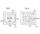
- Figs. 5 and 6 show alternative structures of the dual photodetector 20, which are suitable for use in the present displacement detector.
- a photodetector 50 in the form of a single semiconductor chip is provided with a pair of detector photodiodes 55a and 55b arranged side-by-side with a predetermined gap d therebetween.
- the gap d is set approximately at 10 microns using the beam spot having a diameter of approximately 10 microns as magnified approximately 5 times by the lens, the displacement of the lens in the order of 2 angstroms can be detected.
- the photodetector 55 is also provided with four alignment photodiodes 55c-55f, which are arranged to substantially surround the pair of detector photodiodes 55a and 55b.
- Fig. 6 shows a multiple photodetector 56 which includes a plurality (6 in the illustrated embodiment) of photodiodes 56a arranged in a line as spaced apart from one another over a predetermined distance d with their longitudinal axis directed perpendicular to the line of arrangement. Such a structure allows to expand the operational range of the present displacement detector.
- the photodetector 56 is also provided with alignment photodiodes 56b and 56c.
- a detector for detecting the acceleration, the velocity, the displacement or the vibration of a point of interest at high accuracy and sensitivity.
- the resolution and sensitivity can be increased significantly and the mounting process can be greatly simplified since it does not require the alignment between the two photodiodes.
- the structural integrity is extremely high thereby allowing for use in the roughest condition without causing any problem.
- a rod lens e.g., selfoc lens
- the structural integrity of the detector can be further increased while facilitating the manufacturing process.
Landscapes
- Physics & Mathematics (AREA)
- Engineering & Computer Science (AREA)
- Remote Sensing (AREA)
- Life Sciences & Earth Sciences (AREA)
- General Physics & Mathematics (AREA)
- Acoustics & Sound (AREA)
- Environmental & Geological Engineering (AREA)
- Geology (AREA)
- General Life Sciences & Earth Sciences (AREA)
- Geophysics (AREA)
- Electromagnetism (AREA)
- Measurement Of Mechanical Vibrations Or Ultrasonic Waves (AREA)
Claims (6)
- Ein Servo-Accelerometer, umfassend:
einen festen Support (11) und einen beweglichen Support (12, 13, 15),
mindestens einen Permanentmagneten (17a, 17b) und mindestens eine Spule (16a, 16b), die so positioniert ist, daß sie ein Magnetfeld erzeugen kann, das mit dem Permanentmagneten in magnetische Wechselwirkung tritt, welche Spule und welcher Magnet jeweils an einem der Supports (11 bzw. 12, 13, 15) montiert sind,
eine positionsfeste Lichtquelle (18) für das Emittieren eines Lichtstrahls,
positionsfeste Lichtempfangsmittel (20) für den Empfang des Lichtstrahls von der Lichtquelle (18), welche Lichtempfangsmittel (20) ein für die Auftreffposition des Lichtstrahls indikatives Signal erzeugen,
ein auf dem beweglichen Support (12, 13, 15) fest montiertes optisches System (14) für das Richten des Lichtstrahls von der Lichtquelle auf die Lichtempfangsmittel (20), und
einen Regelverstärker (22) für das Einspeisen eines Erregerstromes in die Spule (16a, 16b) im Ansprechen auf das von den Lichtempfangsmitteln (20) erzeugte Signal,
dadurch gekennzeichnet,
daß das optische System eine an dem beweglichen Support (12, 13, 15) angebrachte Gradientindex-Stablinse umfaßt für das Fokussieren des Lichtstrahls auf die Lichtempfangsmittel (20), und
daß die Lichtempfangsmittel auf einem einzigen Halbleiterchip mindestens zwei Detektor-Photodioden (20a, 20b) umfassen, die voneinander einen vorbestimmten Abstand aufweisen, sowie mindestens eine die Detektor-Photodioden (20a, 20b) mindestens teilweise umschließende Ausfluchtungs-Photodiode (20c). - Das Accelerometer nach Anspruch 1, dadurch gekennzeichnet, daß der Abstand zwischen den beiden Detektor-Photodioden zwischen wenigen Mikrometern und etwa 10 Mikrometern liegt.
- Das Accelerometer nach Anspruch 1 oder 2, dadurch gekennzeichnet, daß die Lichtquelle (18) aus der aus Lichtemissionsdiode, Laserdiode, EL-Komponente und Plasmaentladungskomponente bestehenden Gruppe ausgewählt ist.
- Das Accelerometer nach einem der Ansprüche 1 bis 3, dadurch gekennzeichnet, daß der bewegliche Support (12, 13, 15) umfaßt:
eine vertikale Stützstange (12), in der die Stablinse (14) fest eingefügt ist, und
eine auslenkbare Stützplatte (13), deren eines Ende positionsfest ist und deren entgegengesetztes Ende starr am Fußende der vertikalen Stützstange (12) befestigt ist. - Das Accelerometer nach Anspruch 4, dadurch gekennzeichnet, daß die auslenkbare Verbinderplatte (13) mit einer horizontalen Nut (13a) auf entgegengesetzten Oberflächen derselben versehen ist zum Bereitstellen eines verdünnten Bereichs, wodurch der Verbinderplatte (13) ermöglicht wird, sich längs des verdünnten Bereichs zu biegen.
- Das Accelerometer nach Anspruch 5, dadurch gekennzeichnet, daß die auslenkbare Verbinderplatte (13) mit einem zentralen Loch (13b) versehen ist, um eine vergrößerte Auslenkbarkeit bereitzustellen.
Priority Applications (2)
| Application Number | Priority Date | Filing Date | Title |
|---|---|---|---|
| DE8686402297T DE3683942D1 (de) | 1986-10-15 | 1986-10-15 | Optischer seismikdetektor. |
| EP86402297A EP0264509B1 (de) | 1985-04-16 | 1986-10-15 | Optischer Seismikdetektor |
Applications Claiming Priority (2)
| Application Number | Priority Date | Filing Date | Title |
|---|---|---|---|
| JP60079365A JPH0664084B2 (ja) | 1985-04-16 | 1985-04-16 | 光感震器 |
| EP86402297A EP0264509B1 (de) | 1985-04-16 | 1986-10-15 | Optischer Seismikdetektor |
Publications (2)
| Publication Number | Publication Date |
|---|---|
| EP0264509A1 EP0264509A1 (de) | 1988-04-27 |
| EP0264509B1 true EP0264509B1 (de) | 1992-02-19 |
Family
ID=13687852
Family Applications (1)
| Application Number | Title | Priority Date | Filing Date |
|---|---|---|---|
| EP86402297A Expired EP0264509B1 (de) | 1985-04-16 | 1986-10-15 | Optischer Seismikdetektor |
Country Status (3)
| Country | Link |
|---|---|
| US (1) | US4792931A (de) |
| EP (1) | EP0264509B1 (de) |
| JP (1) | JPH0664084B2 (de) |
Cited By (1)
| Publication number | Priority date | Publication date | Assignee | Title |
|---|---|---|---|---|
| WO2003096071A1 (en) * | 2002-05-10 | 2003-11-20 | Thales Underwater Systems Pty Limited | Improved seismic sensors |
Families Citing this family (21)
| Publication number | Priority date | Publication date | Assignee | Title |
|---|---|---|---|---|
| NL8802000A (nl) * | 1988-08-11 | 1990-03-01 | Jacobus Wilhelmus Petrus Van D | Geofoonstelsel. |
| US4870290A (en) * | 1988-09-26 | 1989-09-26 | Honeywell Inc. | Object motion sensing and measuring apparatus using position sensing detectors |
| JPH0692980B2 (ja) * | 1989-03-24 | 1994-11-16 | リオン株式会社 | 振動測定装置 |
| JP2687242B2 (ja) * | 1989-08-10 | 1997-12-08 | ジェコー株式会社 | サーボ加速度計 |
| US5229603A (en) * | 1990-07-31 | 1993-07-20 | Canon Kabushiki Kaisha | Vibration detection apparatus |
| US5228893A (en) * | 1991-11-27 | 1993-07-20 | At&T Bell Laboratories | Optical fiber tension monitoring technique |
| US5223710A (en) * | 1992-03-06 | 1993-06-29 | Digital Equipment Corporation | Optical angular position sensing system for use with a galvanometer |
| IL107807A0 (en) * | 1993-11-30 | 1994-02-27 | Aaron Lewis | Simple microamplitude vibration detector |
| US5528936A (en) * | 1994-07-25 | 1996-06-25 | Falk; John E. | Optoelectronic spatial acceleration sensor |
| US5936294A (en) * | 1996-05-28 | 1999-08-10 | Motorola, Inc. | Optical semiconductor component and method of fabrication |
| US5789677A (en) * | 1996-12-19 | 1998-08-04 | Infrastructure Instruments Inc. | Dual-axis force feedback accelerometer |
| US6494095B1 (en) * | 2000-03-28 | 2002-12-17 | Opticnet, Inc. | Micro electromechanical switch for detecting acceleration or decelaration |
| US6325172B1 (en) * | 2000-05-25 | 2001-12-04 | Pvt-Wrl, Llc | Geophone including laser interferometer |
| US6867411B2 (en) * | 2000-10-30 | 2005-03-15 | The Charles Stark Draper Laboratory, Inc. | Optically rebalanced accelerometer |
| DE10344558A1 (de) * | 2003-09-25 | 2005-05-12 | Send Signal Elektronik Gmbh | Verfahren und Vorrichtung zur Erfassung von seismisch bedingten Bewegungen |
| US7382002B2 (en) * | 2004-12-09 | 2008-06-03 | Litton Systems, Inc. | Photo-detector and related instruments |
| US8913464B2 (en) | 2010-09-14 | 2014-12-16 | Schlumberger Technology Corporation | Methods and systems for seismic signal detection |
| US9435644B2 (en) | 2013-05-10 | 2016-09-06 | Schlumberger Technology Corporation | Digital compensation for non-linearity in displacement sensors |
| CN111465875A (zh) * | 2017-09-21 | 2020-07-28 | 俄罗斯石油公司 | 地震传感器 |
| US12135398B2 (en) | 2021-12-13 | 2024-11-05 | International Business Machines Corporation | Multiple dipole line trap system |
| US11835333B2 (en) | 2021-12-17 | 2023-12-05 | International Business Machines Corporation | Rotational oscillation sensor with a multiple dipole line trap system |
Family Cites Families (20)
| Publication number | Priority date | Publication date | Assignee | Title |
|---|---|---|---|---|
| US2695165A (en) * | 1950-07-14 | 1954-11-23 | Hughes Aircraft Co | Electromagnetic accelerometer |
| US3564928A (en) * | 1967-08-30 | 1971-02-23 | North American Rockwell | High sensitivity accelerometer |
| NL6801683A (de) * | 1968-02-06 | 1969-08-08 | ||
| US3480908A (en) * | 1968-05-16 | 1969-11-25 | Gravimetrics Inc | Seismograph |
| US4028659A (en) * | 1972-10-18 | 1977-06-07 | Kinemetrics, Inc. | Strong motion accelerograph with self-starter and electrical as well as light outputs |
| US3789674A (en) * | 1972-10-27 | 1974-02-05 | Us Navy | Optical accelerometer |
| GB1513249A (en) * | 1974-09-03 | 1978-06-07 | Decca Ltd | Remote movement detector |
| US3998106A (en) * | 1975-06-30 | 1976-12-21 | The Singer Company | Selective flotation mechanism for a pendulous accelerometer proof mass |
| US4152940A (en) * | 1976-10-15 | 1979-05-08 | Oki Electric Industry Co., Ltd. | Vibration detector |
| JPS5856092B2 (ja) * | 1977-05-09 | 1983-12-13 | 沖電気工業株式会社 | 振動検出装置 |
| US4285570A (en) * | 1977-10-14 | 1981-08-25 | Nippon Electric Company, Ltd. | Light branching device |
| DE3004878C2 (de) * | 1979-02-09 | 1984-04-19 | Ricoh Co., Ltd., Tokio/Tokyo | Einrichtung zur Bestimmung der Scharfeinstellung einer Kamera |
| SU817635A1 (ru) * | 1979-02-28 | 1981-03-30 | Каунасский Политехнический Институтим. Ahtahaca Снечкуса | Автокомпенсатор |
| SE435427B (sv) * | 1979-10-29 | 1984-09-24 | Asea Ab | Anordning for metning av strom, genomflytande en eller flera ljusemitterande strukturer |
| JPS5710551A (en) * | 1980-06-21 | 1982-01-20 | Agency Of Ind Science & Technol | Transmission system of optical information |
| US4376390A (en) * | 1981-03-20 | 1983-03-15 | Sanders Associates, Inc. | Fiber optic angular accelerometer |
| SU962768A1 (ru) * | 1981-03-27 | 1982-09-30 | Могилевский Машиностроительный Институт | Устройство дл контрол параметров вибрации |
| US4409842A (en) * | 1981-05-18 | 1983-10-18 | Scott Science & Technology, Inc. | Structural information detector |
| JPS5890173A (ja) * | 1981-11-25 | 1983-05-28 | Tokyo Keiki Co Ltd | 加速度計の偏位検出装置 |
| US4493212A (en) * | 1982-09-20 | 1985-01-15 | Aetna Telecommunications Laboratories | Fiber optic mass sensor |
-
1985
- 1985-04-16 JP JP60079365A patent/JPH0664084B2/ja not_active Expired - Lifetime
-
1986
- 1986-09-23 US US06/910,585 patent/US4792931A/en not_active Expired - Lifetime
- 1986-10-15 EP EP86402297A patent/EP0264509B1/de not_active Expired
Cited By (1)
| Publication number | Priority date | Publication date | Assignee | Title |
|---|---|---|---|---|
| WO2003096071A1 (en) * | 2002-05-10 | 2003-11-20 | Thales Underwater Systems Pty Limited | Improved seismic sensors |
Also Published As
| Publication number | Publication date |
|---|---|
| JPS61239164A (ja) | 1986-10-24 |
| JPH0664084B2 (ja) | 1994-08-22 |
| US4792931A (en) | 1988-12-20 |
| EP0264509A1 (de) | 1988-04-27 |
Similar Documents
| Publication | Publication Date | Title |
|---|---|---|
| EP0264509B1 (de) | Optischer Seismikdetektor | |
| US7719690B2 (en) | Optical inclination sensor | |
| US4932261A (en) | Micro-machined accelerometer with tilt compensation | |
| US9702992B2 (en) | Closed loop control techniques for displacement sensors with optical readout | |
| US4800267A (en) | Optical fiber microbend horizontal accelerometer | |
| EP0082524A2 (de) | Geophysisches Explorationssystem | |
| US4567771A (en) | Optical accelerometer | |
| US3865467A (en) | Retroreflecting beam splitter and apparatus for measuring gravity gradients embodying the same | |
| US6473187B1 (en) | High-sensitivity interferometric accelerometer | |
| WO2003096071A1 (en) | Improved seismic sensors | |
| US3074279A (en) | Position detecting transducer | |
| EP0229448A2 (de) | Beschleunigungsmesser mit Ringlaser | |
| US5789677A (en) | Dual-axis force feedback accelerometer | |
| EP0175298A2 (de) | Bohrlochmessgerät mit einem optischen Rotationsfühler | |
| US4119173A (en) | Optical seismograph | |
| RU191766U1 (ru) | Устройство для определения колебаний земной поверхности | |
| Lopez-Higuera et al. | New low-cost fiber optic accelerometer system for stator winding monitoring of hydroelectric generating machines | |
| JP2877507B2 (ja) | 重力勾配計 | |
| RU2004787C1 (ru) | Датчик зенитного угла буровой скважины | |
| USRE27532E (en) | Position detecting transducer | |
| JPS61100608A (ja) | 角速度検出器 | |
| CN120891225A (zh) | 基于光强度调制的momes加速度计 | |
| JP3220527B2 (ja) | 光電型エンコーダ及びそれを用いた振動ジャイロ | |
| Hirata et al. | Silicon micromachined fiber-optic accelerometer for downhole seismic measurement | |
| Farah | Interferometric fiber optic accelerometer |
Legal Events
| Date | Code | Title | Description |
|---|---|---|---|
| PUAI | Public reference made under article 153(3) epc to a published international application that has entered the european phase |
Free format text: ORIGINAL CODE: 0009012 |
|
| AK | Designated contracting states |
Kind code of ref document: A1 Designated state(s): DE FR GB IT NL |
|
| 17P | Request for examination filed |
Effective date: 19880928 |
|
| 17Q | First examination report despatched |
Effective date: 19891211 |
|
| GRAA | (expected) grant |
Free format text: ORIGINAL CODE: 0009210 |
|
| AK | Designated contracting states |
Kind code of ref document: B1 Designated state(s): DE FR GB IT NL |
|
| REF | Corresponds to: |
Ref document number: 3683942 Country of ref document: DE Date of ref document: 19920326 |
|
| ITF | It: translation for a ep patent filed | ||
| ET | Fr: translation filed | ||
| PLBE | No opposition filed within time limit |
Free format text: ORIGINAL CODE: 0009261 |
|
| STAA | Information on the status of an ep patent application or granted ep patent |
Free format text: STATUS: NO OPPOSITION FILED WITHIN TIME LIMIT |
|
| 26N | No opposition filed | ||
| PGFP | Annual fee paid to national office [announced via postgrant information from national office to epo] |
Ref country code: GB Payment date: 19981001 Year of fee payment: 13 |
|
| PGFP | Annual fee paid to national office [announced via postgrant information from national office to epo] |
Ref country code: NL Payment date: 19981030 Year of fee payment: 13 |
|
| PGFP | Annual fee paid to national office [announced via postgrant information from national office to epo] |
Ref country code: DE Payment date: 19981214 Year of fee payment: 13 |
|
| PGFP | Annual fee paid to national office [announced via postgrant information from national office to epo] |
Ref country code: FR Payment date: 19990915 Year of fee payment: 14 |
|
| PG25 | Lapsed in a contracting state [announced via postgrant information from national office to epo] |
Ref country code: GB Free format text: LAPSE BECAUSE OF NON-PAYMENT OF DUE FEES Effective date: 19991015 |
|
| PG25 | Lapsed in a contracting state [announced via postgrant information from national office to epo] |
Ref country code: NL Free format text: LAPSE BECAUSE OF NON-PAYMENT OF DUE FEES Effective date: 20000501 |
|
| GBPC | Gb: european patent ceased through non-payment of renewal fee |
Effective date: 19991015 |
|
| NLV4 | Nl: lapsed or anulled due to non-payment of the annual fee |
Effective date: 20000501 |
|
| PG25 | Lapsed in a contracting state [announced via postgrant information from national office to epo] |
Ref country code: DE Free format text: LAPSE BECAUSE OF NON-PAYMENT OF DUE FEES Effective date: 20000801 |
|
| PG25 | Lapsed in a contracting state [announced via postgrant information from national office to epo] |
Ref country code: FR Free format text: LAPSE BECAUSE OF NON-PAYMENT OF DUE FEES Effective date: 20010629 |
|
| REG | Reference to a national code |
Ref country code: FR Ref legal event code: ST |
|
| PG25 | Lapsed in a contracting state [announced via postgrant information from national office to epo] |
Ref country code: IT Free format text: LAPSE BECAUSE OF NON-PAYMENT OF DUE FEES Effective date: 20051015 |