EP0264574B1 - Druckquelle, insbesondere für eine hydraulische Bremsanlage - Google Patents
Druckquelle, insbesondere für eine hydraulische Bremsanlage Download PDFInfo
- Publication number
- EP0264574B1 EP0264574B1 EP87112140A EP87112140A EP0264574B1 EP 0264574 B1 EP0264574 B1 EP 0264574B1 EP 87112140 A EP87112140 A EP 87112140A EP 87112140 A EP87112140 A EP 87112140A EP 0264574 B1 EP0264574 B1 EP 0264574B1
- Authority
- EP
- European Patent Office
- Prior art keywords
- pressure
- pump
- pressure source
- accumulator
- reducing means
- Prior art date
- Legal status (The legal status is an assumption and is not a legal conclusion. Google has not performed a legal analysis and makes no representation as to the accuracy of the status listed.)
- Expired - Lifetime
Links
Images
Classifications
-
- B—PERFORMING OPERATIONS; TRANSPORTING
- B60—VEHICLES IN GENERAL
- B60T—VEHICLE BRAKE CONTROL SYSTEMS OR PARTS THEREOF; BRAKE CONTROL SYSTEMS OR PARTS THEREOF, IN GENERAL; ARRANGEMENT OF BRAKING ELEMENTS ON VEHICLES IN GENERAL; PORTABLE DEVICES FOR PREVENTING UNWANTED MOVEMENT OF VEHICLES; VEHICLE MODIFICATIONS TO FACILITATE COOLING OF BRAKES
- B60T17/00—Component parts, details, or accessories of power brake systems not covered by groups B60T8/00, B60T13/00 or B60T15/00, or presenting other characteristic features
- B60T17/02—Arrangements of pumps or compressors, or control devices therefor
-
- B—PERFORMING OPERATIONS; TRANSPORTING
- B60—VEHICLES IN GENERAL
- B60T—VEHICLE BRAKE CONTROL SYSTEMS OR PARTS THEREOF; BRAKE CONTROL SYSTEMS OR PARTS THEREOF, IN GENERAL; ARRANGEMENT OF BRAKING ELEMENTS ON VEHICLES IN GENERAL; PORTABLE DEVICES FOR PREVENTING UNWANTED MOVEMENT OF VEHICLES; VEHICLE MODIFICATIONS TO FACILITATE COOLING OF BRAKES
- B60T8/00—Arrangements for adjusting wheel-braking force to meet varying vehicular or ground-surface conditions, e.g. limiting or varying distribution of braking force
- B60T8/32—Arrangements for adjusting wheel-braking force to meet varying vehicular or ground-surface conditions, e.g. limiting or varying distribution of braking force responsive to a speed condition, e.g. acceleration or deceleration
- B60T8/34—Arrangements for adjusting wheel-braking force to meet varying vehicular or ground-surface conditions, e.g. limiting or varying distribution of braking force responsive to a speed condition, e.g. acceleration or deceleration having a fluid pressure regulator responsive to a speed condition
- B60T8/40—Arrangements for adjusting wheel-braking force to meet varying vehicular or ground-surface conditions, e.g. limiting or varying distribution of braking force responsive to a speed condition, e.g. acceleration or deceleration having a fluid pressure regulator responsive to a speed condition comprising an additional fluid circuit including fluid pressurising means for modifying the pressure of the braking fluid, e.g. including wheel driven pumps for detecting a speed condition, or pumps which are controlled by means independent of the braking system
- B60T8/4036—Pump units characterised by their failure-responsive means
-
- F—MECHANICAL ENGINEERING; LIGHTING; HEATING; WEAPONS; BLASTING
- F15—FLUID-PRESSURE ACTUATORS; HYDRAULICS OR PNEUMATICS IN GENERAL
- F15B—SYSTEMS ACTING BY MEANS OF FLUIDS IN GENERAL; FLUID-PRESSURE ACTUATORS, e.g. SERVOMOTORS; DETAILS OF FLUID-PRESSURE SYSTEMS, NOT OTHERWISE PROVIDED FOR
- F15B1/00—Installations or systems with accumulators; Supply reservoir or sump assemblies
- F15B1/02—Installations or systems with accumulators
- F15B1/027—Installations or systems with accumulators having accumulator charging devices
- F15B1/033—Installations or systems with accumulators having accumulator charging devices with electrical control means
Definitions
- the invention relates to a pressure source, in particular for a hydraulic brake system, consisting of an accumulator, a pump and a pressure switch, which switches off the pump drive when the target pressure in the accumulator is reached, a relief line branching off the pump delivery flow, into which a safety device is switched on.
- an overpressure valve is provided in the known device as a safety device, which limits the pressure to a certain level.
- the pump constantly works against a very high pressure if the pressure switch is inoperative, so that overheating of the pump and the pump drive cannot be ruled out. It is therefore necessary to provide an overheating switch that switches off the pump drive in the event of overheating. Shutting off the pump or destroying it if no overheating switch is provided means that after the storage tank has been drained of pressure, no pressure medium can be made available under pressure.
- Such a device can not be used in particular in the pressure source for the brake system of a motor vehicle, since, in the event that the rupture disc safety device is activated, no more pressure can be built up in the memory, and depending on the type of brake system, braking the vehicle is impossible becomes.
- the invention is therefore based on the object of creating a pressure source which works when the pressure switch is inoperative in such a way that too high a pressure is not built up in the memory, and the pressure supply does not completely collapse. At the same time, overheating of the pump and the pump drive should be avoided.
- the safety device has a rupture disk and a pressure reducing device connected downstream of the rupture disk.
- the operational safety of the pressure source is ensured by connecting a check valve between the pump and the accumulator, which opens towards the accumulator.
- the pressure minority can be realized in different ways.
- a throttle can be provided. This choke is simple and cheap to manufacture. However, the pressure drop depends on the pressure medium flow.
- Another possibility is to represent the pressure reducing unit by means of a pressure differential valve, e.g. a spring-loaded check valve can be used.
- a pressure differential valve e.g. a spring-loaded check valve
- a favorable arrangement of the elements is obtained if the safety device is connected in a line between the pump outlet and an unpressurized expansion tank.
- the design of the throttle or the pressure differential valve is linked in a favorable manner with the continuous load capacity of the pump and the pump drive. This is achieved in that the components of the pressure reducing device, which determine the back pressure upstream of the pressure reducing device, are designed such that, in the event of a defective pressure switch and broken rupture disk, the pump works continuously against the back pressure without overheating.
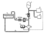
- the reservoir 1 is supplied with pressure medium under pressure by the pump 2, which is driven by the electric motor 3, via the pressure medium line 4 and the check valve 5.
- the pump inlet is connected to a pressure-free expansion tank 7 via a pressure medium line 6.
- the pressure in the memory 1 is passed on to a consumer 8, in particular the braking system of a vehicle.
- the pressure switch 9 is used to regulate the pressure in the store 1. If a specific target pressure is reached, the pressure switch 9 switches off the drive motor 3 of the pump 2, so that no further pressure increase can take place.
- a pressure line 10 branches off from the pressure line 4 to the unpressurized expansion tank 7.
- a rupture disk 11 is first connected to this pressure line and then a throttle 13 or a pressure differential valve 14.
- the pressure source works in the manner already described.
- the pump 2 is driven until the setpoint pressure has built up in the store 1 and the pump drive 3 is switched off using the pressure switch 9.
- the pump drive 3 is not switched off and a pressure is built up in the memory which is above the set pressure. This pressure is not only present in the reservoir 1, but also in front of the rupture disk 11.
- the pump outlet is connected to the unpressurized expansion tank 7. So that there is no complete pressure drop, a throttle 13 or a pressure differential valve 14 is connected in line 10, so that a small residual pressure remains at the pump outlet. This can e.g. be 40 bar if the normal pressure in the accumulator is approx. 180 bar.
Landscapes
- Engineering & Computer Science (AREA)
- Physics & Mathematics (AREA)
- Fluid Mechanics (AREA)
- Mechanical Engineering (AREA)
- Transportation (AREA)
- General Engineering & Computer Science (AREA)
- Valves And Accessory Devices For Braking Systems (AREA)
- Fluid-Pressure Circuits (AREA)
Description
- Die Erfindung bezieht sich auf eine Druckquelle, insbesondere für eine hydraulische Bremsanlage, bestehend aus enem Speicher, einer Pumpe und einem Druckschalter, der den Pumpenantrieb bei Erreichen des Solldrucks im Speicher abschaltet, wobei vom Pumpenförderstrom eine Entlastungsleitung abzweigt, in die eine Sicherheitseinrichtung eingeschaltet ist.
- Eine derartige Druckquelle ist in der nicht vorveröffentlichten DE-A 3 541 833 (OT 4.6.87 der A. Teves GmbH beschrieben.
- Damit bei einer Funktionsunfähigkeit des Druckschalters der Speicher und die angeschlossenen Verbraucher nicht mit zu großen Drücken versorgt werden, ist bei der bekannten Einrichtung als Sicherheitseinrichtung ein Überdruckventil vorgesehen, das den Druck auf ein bestimmtes Niveau begrenzt.
- Bei dieser Anlage arbeitet die Pumpe bei Funktionsunfähigkeit des Druckschalters ständig gegen einen sehr hohen Druck, so daß eine Überhitzung der Pumpe und des Pumpenantriebs nicht ausgeschlossen werden kann. Es ist daher ein Überhitzungsschalter vorzusehen, der den Pumpenantrieb bei Überhitzung ausschaltet. Das Abschaften der Pumpe bzw. ihre Zerstörung, wenn kein Überhitzungsschalter vorgesehen ist, hat zur Folge, daß nach Druckentleerung des Speichers kein Druckmittel unter Druck mehr zur Verfügung gestellt werden kann.
- Aus der DE-A 2 009 526 ist weiterhin eine Berstscheibensicherheitseinrichtung für einen Druckbehälter bekannt geworden.
- Eine derartige Einrichtung kann aber insbesondere bei der Druckquelle für die Bremsanlage eines Kraftfahrzeuges nicht eingesetzt werden, da, für den Fall, daß die Berstscheibensicherheitseinrichtung aktiviert wird, kein Druck mehr im Speicher aufgebaut werden kann, und je nach Art der Bremsanlage eine Abbremsung des Fahrzeugs unmöglich wird.
- Die Erfindung geht daher von der Aufgabe aus, eine Druckquelle zu schaffen, die bei Funktionsunfähigkeit des Druckschafters so arbeitet, daß im Speicher weder ein zu hoher Druck aufgebaut wird, noch die Druckversorgung vollständig zusammenfällt. Gleichzeitig soll eine Uberhitzung der Pumpe und des Pumpenantriebs vermieden werden.
- Die Aufgabe wird dadurch gelöst, daß die Sicherheitseinrichtung eine Berstscheibe und eine der Berstscheibe nachgeschaltete Druckmindereinrichtung aufweist.
- Die Betriebssicherheit der Druckquelle wird sichergestellt, indem zwischen die Pumpe und den Speicher ein Rückschlagventil geschaltet wird, das zum Speicher hin öffnet.
- Die Druckminderenheit kann in verschiedener Weise realisiert werden. Zum einen kann eine Drossel vorgesehen werden. Diese Drossel ist einfach und billig herzustellen. Das Druckgefälle hängt allerdings vom Druckmittelstrom ab.
- Eine weitere Möglichkeit besteht darin, die Druckmindereinheit durch ein Druckdifferenzventil darzustellen, wobei z.B. ein federkraftbeaufschagtes Rückschlagventil zum Einsatz kommen kann.
- Eine günstige Anordnung der Elemente erhält man, wenn die Sicherheitseinrichtung in eine Leitung zwischen dem Pumpenausgang und einem drucklosen Ausgleichsbehälter geschaltet ist.
- Die Auslegung der Drossel bzw. des Druckdifferenzventils wird in günstiger Weise mit der Dauerbelastungsfähigkeit der Pumpe und des Pumpenantriebs verknüpft. Dies wird dadurch erreicht, daß die Bauelemente der Druckmindereinrichtung, die den Staudruck vor der Druckmindereinrichtung bestimmen, so ausgebildet sind, daß bei einem defekten Druckschalter und gebrochener Berstscheibe die Pumpe ständig, ohne Überhitzung, gegen den Staudruck arbeitet.
- In der Figur ist schematisch ein Ausführungsbeispiel der Erfindung dargestellt. Der Speicher 1 wird über die Druckmittelleitung 4 und dem Rückschlagventil 5 von der Pumpe 2, die von dem Elektromotor 3 angetrieben wird, mit Druckmittel unter Druck versorgt.
- Der Pumpeneingang ist über eine Druckmittelleitung 6 an einen drucklosen Ausgleichsbehälter 7 angeschlossen.
- Der Druck im Speicher 1 wird an einen Verbraucher 8, das ist insbesondere die Bremsanlage von einem Fahrzeug, weitergeleitet.
- Mit dem Druckschalter 9 erfolgt eine Regelung des Drucks im Speicher 1. Wird ein bestimmter Solldruck erreicht, so schaltet der Druckschalter 9 den Antriebsmotor 3 der Pumpe 2 aus, so daß keine weitere Druckerhöhung erfolgen kann.
- Von der Druckleitung 4 zweigt eine Druckleitung 10 zum drucklosen Ausgleichsbehälter 7 ab. In diese Druckleitung ist zunächst eine Berstscheibe 11 geschaltet und dann eine Drossel 13 bzw. ein Druckdifferenzventil 14.
- Im Normalfall arbeitet die Druckquelle in der schon beschriebenen Art. Die Pumpe 2 wird so lange angetrieben, bis sich im Speicher 1 der Solldruck aufgebaut hat und mt Hilfe des Druckschalters 9 der Pumpenantrieb 3 ausgeschaltet wird.
- Sollte diese Schaltung versagen, so wird der Pumpenantrieb 3 nicht ausgeschaltet, und es wird im Speicher ein Druck aufgebaut, der über dem Solldruck liegt. Dieser Druck steht nicht nur im Speicher 1, sondern auch vor der Berstscheibe 11 an.
- Sobald der Berstdruck erreicht ist, also der Druck, bei dem die Scheibe aufgrund ihrer Konstruktion bricht, ist der Pumpenausgang an den drucklosen Ausgleichsbehälter 7 angeschlossen. Damit kein vollständiger Druckabfall erfolgt, ist in die Leitung 10 eine Drossel 13 bzw. ein Druckdifferenzventil 14 geschaltet, so daß am Pumpenausgang ein geringer Restdruck verbleibt. Dieser kann z.B. bei 40 bar liegen, wenn der Normaldruck im Speicher bei ca. 180 bar liegt.
- Da der Druckschalter 9 weiterhin funktionsunfähig ist, wird die Pumpe gegen dieses Druckmittel zum Verbraucher 8 in den Speicher 1 und in den Ausgleichsbehälter 7 pumpen. Die dabei umgesetzte Energie ist aber nicht so groß, daß dies zu einer Überhitzung von Pumpe und Pumpenantrieb führt. Gleichzeitig wird dem Verbraucher aber ein Druck zur Verfügung gestellt, der eine Notbetätigung des Verbrauchers möglich macht.
-
- 1 Speicher
- 2 Pumpe
- 3 Pumpenantrieb
- 4 Druckleitung
- 5 Rückschlagventil
- 6 Druckleitung
- 7 Ausgleichsbehälter
- 8 Verbraucher
- 9 Druckschalter
- 10 Druckleitung
- 11 Berstscheibe
- 12 Druckmindereinrichtung
- 13 Drossel
- 14 Druckreduzierventil
Claims (6)
Applications Claiming Priority (2)
| Application Number | Priority Date | Filing Date | Title |
|---|---|---|---|
| DE19863635055 DE3635055A1 (de) | 1986-10-15 | 1986-10-15 | Druckquelle, insbesondere fuer eine hydraulische bremsanlage |
| DE3635055 | 1986-10-15 |
Publications (3)
| Publication Number | Publication Date |
|---|---|
| EP0264574A2 EP0264574A2 (de) | 1988-04-27 |
| EP0264574A3 EP0264574A3 (en) | 1989-01-11 |
| EP0264574B1 true EP0264574B1 (de) | 1990-05-09 |
Family
ID=6311752
Family Applications (1)
| Application Number | Title | Priority Date | Filing Date |
|---|---|---|---|
| EP87112140A Expired - Lifetime EP0264574B1 (de) | 1986-10-15 | 1987-08-21 | Druckquelle, insbesondere für eine hydraulische Bremsanlage |
Country Status (2)
| Country | Link |
|---|---|
| EP (1) | EP0264574B1 (de) |
| DE (2) | DE3635055A1 (de) |
Families Citing this family (5)
| Publication number | Priority date | Publication date | Assignee | Title |
|---|---|---|---|---|
| DE4030862A1 (de) * | 1990-09-29 | 1992-04-02 | Bosch Gmbh Robert | Hydraulisches system, wie kraftfahrzeug-bremsanlage oder dergleichen |
| DE4241095A1 (de) * | 1992-12-07 | 1994-06-09 | Teves Gmbh Alfred | Druckversorgung, insbesondere für eine hydraulische Bremsanlage |
| DE10060608C1 (de) * | 2000-12-05 | 2002-04-18 | Webasto Thermosysteme Gmbh | Vorrichtung zum Verschluß der Rücklaufbohrung einer Hochdruckpumpe |
| FR2938021A1 (fr) * | 2008-11-06 | 2010-05-07 | Afhymat | Dispositif de protection pour actionneur hydraulique |
| CN114278626B (zh) * | 2021-12-23 | 2023-11-07 | 中国航空工业集团公司金城南京机电液压工程研究中心 | 一种电动增压储能流量补偿的机载应急液压系统及方法 |
Citations (2)
| Publication number | Priority date | Publication date | Assignee | Title |
|---|---|---|---|---|
| DE2009526A1 (de) * | 1970-02-28 | 1971-09-09 | Black Sivalls & Bryson Inc | Sicherheitsschaltvornchtung fur einen Druckkessel mit einer sich ausbeulenden Zerreisscheibe |
| DE3541833A1 (de) * | 1985-11-27 | 1987-06-04 | Teves Gmbh Alfred | Schlupfgeregelte bremsanlage |
Family Cites Families (11)
| Publication number | Priority date | Publication date | Assignee | Title |
|---|---|---|---|---|
| DE724070C (de) * | 1939-03-22 | 1942-08-17 | Cie Internationale Des Freins | Hydropneumatische Bremseinrichtung fuer Fahrzeuge |
| GB820897A (en) * | 1956-08-13 | 1959-09-30 | Aro Equipment Corp | Improvements in or relating to relief valves |
| GB1202673A (en) * | 1968-04-05 | 1970-08-19 | Alfred Fischbach | Hydraulic supply systems |
| FR2121951A5 (de) * | 1971-01-13 | 1972-08-25 | Agiman Jacques | |
| FR2134126B1 (de) * | 1971-04-21 | 1975-07-04 | Dba | |
| GB1373143A (en) * | 1973-02-23 | 1974-11-06 | Marston Excelsior Ltd | Safety pressure relief apparatus |
| DE2555460C2 (de) * | 1975-12-10 | 1982-11-18 | FAG Kugelfischer Georg Schäfer & Co, 8720 Schweinfurt | Auslösevorrichtung für einen pneumatischen Temperaturwächter |
| US4041990A (en) * | 1976-04-05 | 1977-08-16 | The Bendix Corporation | Accumulator for use in a hydraulic system |
| DD133840A1 (de) * | 1977-10-31 | 1979-01-24 | Dieter Kabisch | Einrichtung zum auffuellen von druckfluessigkeitsspeichern mit druckoel |
| JPS57164395U (de) * | 1981-04-10 | 1982-10-16 | ||
| DE3512110A1 (de) * | 1985-04-03 | 1986-10-09 | Alfred Teves Gmbh, 6000 Frankfurt | Vorrichtung zur ueberwachung einer hydraulikanlage |
-
1986
- 1986-10-15 DE DE19863635055 patent/DE3635055A1/de not_active Withdrawn
-
1987
- 1987-08-21 DE DE8787112140T patent/DE3762652D1/de not_active Expired - Lifetime
- 1987-08-21 EP EP87112140A patent/EP0264574B1/de not_active Expired - Lifetime
Patent Citations (2)
| Publication number | Priority date | Publication date | Assignee | Title |
|---|---|---|---|---|
| DE2009526A1 (de) * | 1970-02-28 | 1971-09-09 | Black Sivalls & Bryson Inc | Sicherheitsschaltvornchtung fur einen Druckkessel mit einer sich ausbeulenden Zerreisscheibe |
| DE3541833A1 (de) * | 1985-11-27 | 1987-06-04 | Teves Gmbh Alfred | Schlupfgeregelte bremsanlage |
Also Published As
| Publication number | Publication date |
|---|---|
| DE3762652D1 (de) | 1990-06-13 |
| EP0264574A3 (en) | 1989-01-11 |
| EP0264574A2 (de) | 1988-04-27 |
| DE3635055A1 (de) | 1988-04-21 |
Similar Documents
| Publication | Publication Date | Title |
|---|---|---|
| WO1998031576A1 (de) | Hydraulische fahrzeugbremsanlage | |
| DE102010053811A1 (de) | Störungssicheres Betätigungssystem | |
| EP2675672B1 (de) | Mehrkreisschutzventil für eine druckluftversorgungseinrichtung eines fahrzeugs und verfahren zum betreiben eines mehrkreisschutzventils | |
| DE69410330T2 (de) | Hydraulikanlage | |
| DE2143733A1 (de) | Vierkreis-schutzventil | |
| EP0264574A2 (de) | Druckquelle, insbesondere für eine hydraulische Bremsanlage | |
| EP1527974B1 (de) | Luftaufbereitungsanlage und Verfahren zum Versorgen einer Nutzkraftfahrzeugbremsanlage mit Druckluft | |
| DE2941566A1 (de) | Steuersystem fuer eine fahrzeugbremsanlage | |
| EP3411275B1 (de) | Bremssystem für ein nutzfahrzeug | |
| DE2233144B2 (de) | Absperrvorrichtung für den oder die beschädigten Bremskreise einer pneumatischen Fahrzeug-Mehrkreisbremsanlage | |
| DE102004021242A1 (de) | Luftaufbereitungsanlage und Verfahren zum Versorgen einer Nutzkraftfahrzeugbremsanlage mit Druckluft | |
| EP0749380B1 (de) | Hydraulische bremsanlage mit bremsschlupf- und antriebsschlupfregelung | |
| DE2212912C3 (de) | Blockierschutz-Einrichtung für Kraftfahrzeuge | |
| DE19740358C2 (de) | Druckhaltevorrichtung | |
| DE1555083A1 (de) | Vorrichtung zum Ablassen des Druckes von Druckakkumulatoren | |
| DE2733883A1 (de) | Fluiddruckbetaetigtes antiblockier- bremssystem | |
| DE2852724C3 (de) | Hydraulisch betriebene Lenkanlage mit Druckregeleinrichtung | |
| DE102018006380A1 (de) | System zum Laden und Entladen mindestens eines Hydrospeichers | |
| DE2047960C2 (de) | Steuereinrichtung einer Konstantdruck-Hydraulikanlage | |
| DE4301012C2 (de) | Speicherschaltung für einen Lenkkreislauf | |
| DE2504712A1 (de) | Vorrichtung zum fuellen mehrerer druckspeicher, insbesondere bei kraftfahrzeugen | |
| DE2023660A1 (de) | Hydraulikanordnung | |
| DE1500256C3 (de) | Sicherheitseinrichtung für Druckmittelbehälter | |
| DE2232120A1 (de) | Vierkreis-schutzventil | |
| DE69507867T2 (de) | Hydraulisches System zum Steuern der Neigung eines Eisenbahnwagenkastens mit einer Vorrichtung zur Druckentlastung eines Stelltriebs |
Legal Events
| Date | Code | Title | Description |
|---|---|---|---|
| PUAI | Public reference made under article 153(3) epc to a published international application that has entered the european phase |
Free format text: ORIGINAL CODE: 0009012 |
|
| 17P | Request for examination filed |
Effective date: 19870821 |
|
| AK | Designated contracting states |
Kind code of ref document: A2 Designated state(s): DE FR GB IT |
|
| PUAL | Search report despatched |
Free format text: ORIGINAL CODE: 0009013 |
|
| AK | Designated contracting states |
Kind code of ref document: A3 Designated state(s): DE FR GB IT |
|
| 17Q | First examination report despatched |
Effective date: 19890811 |
|
| ITF | It: translation for a ep patent filed | ||
| GRAA | (expected) grant |
Free format text: ORIGINAL CODE: 0009210 |
|
| AK | Designated contracting states |
Kind code of ref document: B1 Designated state(s): DE FR GB IT |
|
| REF | Corresponds to: |
Ref document number: 3762652 Country of ref document: DE Date of ref document: 19900613 |
|
| ET | Fr: translation filed | ||
| GBT | Gb: translation of ep patent filed (gb section 77(6)(a)/1977) | ||
| PLBI | Opposition filed |
Free format text: ORIGINAL CODE: 0009260 |
|
| 26 | Opposition filed |
Opponent name: BENDIX EUROPE SERVICES TECHNIQUES Effective date: 19901015 |
|
| ITTA | It: last paid annual fee | ||
| PLBN | Opposition rejected |
Free format text: ORIGINAL CODE: 0009273 |
|
| STAA | Information on the status of an ep patent application or granted ep patent |
Free format text: STATUS: OPPOSITION REJECTED |
|
| 27O | Opposition rejected |
Effective date: 19911116 |
|
| PGFP | Annual fee paid to national office [announced via postgrant information from national office to epo] |
Ref country code: FR Payment date: 19920724 Year of fee payment: 6 |
|
| PGFP | Annual fee paid to national office [announced via postgrant information from national office to epo] |
Ref country code: GB Payment date: 19920804 Year of fee payment: 6 |
|
| PGFP | Annual fee paid to national office [announced via postgrant information from national office to epo] |
Ref country code: DE Payment date: 19920911 Year of fee payment: 6 |
|
| PG25 | Lapsed in a contracting state [announced via postgrant information from national office to epo] |
Ref country code: GB Effective date: 19930821 |
|
| GBPC | Gb: european patent ceased through non-payment of renewal fee |
Effective date: 19930821 |
|
| PG25 | Lapsed in a contracting state [announced via postgrant information from national office to epo] |
Ref country code: FR Effective date: 19940429 |
|
| REG | Reference to a national code |
Ref country code: FR Ref legal event code: ST |
|
| PG25 | Lapsed in a contracting state [announced via postgrant information from national office to epo] |
Ref country code: DE Effective date: 19940901 |
|
| PG25 | Lapsed in a contracting state [announced via postgrant information from national office to epo] |
Ref country code: IT Free format text: LAPSE BECAUSE OF NON-PAYMENT OF DUE FEES;WARNING: LAPSES OF ITALIAN PATENTS WITH EFFECTIVE DATE BEFORE 2007 MAY HAVE OCCURRED AT ANY TIME BEFORE 2007. THE CORRECT EFFECTIVE DATE MAY BE DIFFERENT FROM THE ONE RECORDED. Effective date: 20050821 |