EP0264690A2 - Verfahren und Vorrichtung zur Entschäumung - Google Patents
Verfahren und Vorrichtung zur Entschäumung Download PDFInfo
- Publication number
- EP0264690A2 EP0264690A2 EP87114401A EP87114401A EP0264690A2 EP 0264690 A2 EP0264690 A2 EP 0264690A2 EP 87114401 A EP87114401 A EP 87114401A EP 87114401 A EP87114401 A EP 87114401A EP 0264690 A2 EP0264690 A2 EP 0264690A2
- Authority
- EP
- European Patent Office
- Prior art keywords
- central
- liquid
- foam
- amount
- foam channel
- Prior art date
- Legal status (The legal status is an assumption and is not a legal conclusion. Google has not performed a legal analysis and makes no representation as to the accuracy of the status listed.)
- Granted
Links
- 238000000034 method Methods 0.000 title claims description 6
- 239000007788 liquid Substances 0.000 claims abstract description 22
- 239000006260 foam Substances 0.000 claims abstract description 17
- 238000005188 flotation Methods 0.000 claims abstract description 16
- 239000000725 suspension Substances 0.000 claims description 4
- 238000007872 degassing Methods 0.000 claims description 2
- 230000000149 penetrating effect Effects 0.000 claims 1
- 238000010586 diagram Methods 0.000 description 2
- 238000005336 cracking Methods 0.000 description 1
- 238000000605 extraction Methods 0.000 description 1
- 239000010802 sludge Substances 0.000 description 1
Images

Classifications
-
- B—PERFORMING OPERATIONS; TRANSPORTING
- B03—SEPARATION OF SOLID MATERIALS USING LIQUIDS OR USING PNEUMATIC TABLES OR JIGS; MAGNETIC OR ELECTROSTATIC SEPARATION OF SOLID MATERIALS FROM SOLID MATERIALS OR FLUIDS; SEPARATION BY HIGH-VOLTAGE ELECTRIC FIELDS
- B03D—FLOTATION; DIFFERENTIAL SEDIMENTATION
- B03D1/00—Flotation
- B03D1/14—Flotation machines
- B03D1/1418—Flotation machines using centrifugal forces
-
- B—PERFORMING OPERATIONS; TRANSPORTING
- B01—PHYSICAL OR CHEMICAL PROCESSES OR APPARATUS IN GENERAL
- B01D—SEPARATION
- B01D19/00—Degasification of liquids
- B01D19/02—Foam dispersion or prevention
-
- B—PERFORMING OPERATIONS; TRANSPORTING
- B03—SEPARATION OF SOLID MATERIALS USING LIQUIDS OR USING PNEUMATIC TABLES OR JIGS; MAGNETIC OR ELECTROSTATIC SEPARATION OF SOLID MATERIALS FROM SOLID MATERIALS OR FLUIDS; SEPARATION BY HIGH-VOLTAGE ELECTRIC FIELDS
- B03D—FLOTATION; DIFFERENTIAL SEDIMENTATION
- B03D1/00—Flotation
- B03D1/02—Froth-flotation processes
-
- B—PERFORMING OPERATIONS; TRANSPORTING
- B03—SEPARATION OF SOLID MATERIALS USING LIQUIDS OR USING PNEUMATIC TABLES OR JIGS; MAGNETIC OR ELECTROSTATIC SEPARATION OF SOLID MATERIALS FROM SOLID MATERIALS OR FLUIDS; SEPARATION BY HIGH-VOLTAGE ELECTRIC FIELDS
- B03D—FLOTATION; DIFFERENTIAL SEDIMENTATION
- B03D1/00—Flotation
- B03D1/14—Flotation machines
- B03D1/1443—Feed or discharge mechanisms for flotation tanks
- B03D1/1462—Discharge mechanisms for the froth
-
- B—PERFORMING OPERATIONS; TRANSPORTING
- B03—SEPARATION OF SOLID MATERIALS USING LIQUIDS OR USING PNEUMATIC TABLES OR JIGS; MAGNETIC OR ELECTROSTATIC SEPARATION OF SOLID MATERIALS FROM SOLID MATERIALS OR FLUIDS; SEPARATION BY HIGH-VOLTAGE ELECTRIC FIELDS
- B03D—FLOTATION; DIFFERENTIAL SEDIMENTATION
- B03D1/00—Flotation
- B03D1/14—Flotation machines
- B03D1/1443—Feed or discharge mechanisms for flotation tanks
- B03D1/1475—Flotation tanks having means for discharging the pulp, e.g. as a bleed stream
-
- B—PERFORMING OPERATIONS; TRANSPORTING
- B03—SEPARATION OF SOLID MATERIALS USING LIQUIDS OR USING PNEUMATIC TABLES OR JIGS; MAGNETIC OR ELECTROSTATIC SEPARATION OF SOLID MATERIALS FROM SOLID MATERIALS OR FLUIDS; SEPARATION BY HIGH-VOLTAGE ELECTRIC FIELDS
- B03D—FLOTATION; DIFFERENTIAL SEDIMENTATION
- B03D1/00—Flotation
- B03D1/14—Flotation machines
- B03D1/1406—Flotation machines with special arrangement of a plurality of flotation cells, e.g. positioning a flotation cell inside another
-
- B—PERFORMING OPERATIONS; TRANSPORTING
- B03—SEPARATION OF SOLID MATERIALS USING LIQUIDS OR USING PNEUMATIC TABLES OR JIGS; MAGNETIC OR ELECTROSTATIC SEPARATION OF SOLID MATERIALS FROM SOLID MATERIALS OR FLUIDS; SEPARATION BY HIGH-VOLTAGE ELECTRIC FIELDS
- B03D—FLOTATION; DIFFERENTIAL SEDIMENTATION
- B03D1/00—Flotation
- B03D1/14—Flotation machines
- B03D1/1412—Flotation machines with baffles, e.g. at the wall for redirecting settling solids
-
- B—PERFORMING OPERATIONS; TRANSPORTING
- B03—SEPARATION OF SOLID MATERIALS USING LIQUIDS OR USING PNEUMATIC TABLES OR JIGS; MAGNETIC OR ELECTROSTATIC SEPARATION OF SOLID MATERIALS FROM SOLID MATERIALS OR FLUIDS; SEPARATION BY HIGH-VOLTAGE ELECTRIC FIELDS
- B03D—FLOTATION; DIFFERENTIAL SEDIMENTATION
- B03D1/00—Flotation
- B03D1/14—Flotation machines
- B03D1/1443—Feed or discharge mechanisms for flotation tanks
- B03D1/1456—Feed mechanisms for the slurry
Definitions
- the invention relates to a method for defoaming according to the preamble of claim 1 and useful devices therefor.
- the liquid cleaned in the secondary flotation stage is fed back to the primary flotation stage. This is where the invention intervenes and solves the problem of enabling trouble-free pump operation without oversizing the pump.
- the apparatus according to the invention is shown at 10 in the circuit diagram.
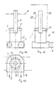
- the liquid inlet connection of the apparatus 10 is designated 5 and the discharge connection 6. They are arranged in parallel and are located on the same side of the lower part 1, namely at its edges, so that both the supply and the discharge of the liquid takes place tangentially.
- the lower part 1 is followed by the concentric central part 2, the radius of which is at least about 20% smaller than that of the rounded wall part of the lower part 1, which is opposite the supply and discharge connections.
- the height of the cylindrical part 2 is at least as large as its diameter.
- the entry region in the upper part of the middle part 2 for the foamed liquid is formed by a pot-like part 3, which forms an annular entry cross section 17 to the upper edge of the middle part 2.
- the gas exhaust pipe 4 projects centrally through the pot part 3 and into the upper region of the middle part 2. It's going up preferably led beyond the overflow edge 8 of the foam extraction weir 24 shown in broken lines and preferably still ends within the foam channel 22, also shown in broken lines.
- One boundary wall of this foam channel is the side wall 20 of the flotation cell arrangement 20 of the primary stage (also shown in broken lines).
- the diameter of the gas exhaust pipe 4 is preferably at least 60% smaller than the diameter of the central part 2.
- the central part 2 preferably projects a small distance (approximately 20% of the height of the lower part 1) into the lower part 1.
- the diameter ratio of the middle part 2 to the cylinder corresponding to the round walls of the lower part 1 is preferably between 0.6 and 08.
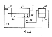
- FIG. 2 shows the arrangement of the apparatus 10 in the foam channel 22 of the primary flotation cell arrangement 20 with the entrance area 21.
- the pump 35 conveys the cleaned amount of recirculation liquid drawn off from the secondary flotation cell arrangement 30 provided with foam drainage channel 31 into the apparatus 10; the other part enters the input part 21 of the primary flotation cell arrangement 20 via line 43.
- the amount of recirculation liquid introduced into the inlet connection 5 generates a rotational flow in the lower part 1, essentially in the form of a potential vortex, which also propagates into the central part 2 and thus also detects the foamed liquid quantity of the foam discharge channel 22, as a result of which the gas contained therein (Air) collects centrally and can be discharged via the gas exhaust pipe 4.
- the cross-section of the discharge nozzle 6 is chosen to be somewhat larger than that of the feed nozzle 5, since a larger amount must be removed than is supplied.
- the amount of recirculation to be supplied by the apparatus 10 is 60-85% of the total amount of recirculation, so that only the smaller remainder is fed to the input part 21 of the primary flotation cell arrangement via line 43, with a flotation sludge discharge of approximately 3%.
- FIGS. 3a and 3b show another embodiment of the degassing device in which the middle part of FIGS. 1a to 1c is the upper part 2 ⁇ of the device. For this, the lower part 1 ⁇ is divided into two parts lying one above the other.
- the figures of this device have the corresponding reference numerals for the essentially same parts as in FIGS. 1a to 1c, but with a comma.
- the upper part 31 of the lower part 1 ⁇ is designed as an inlet spiral for the amount of suspension carried in the bypass, as can be seen from FIG. 3b.
- the entry region of the lower part 32 has an inlet funnel 34 which tapers downwards, the inclination of its generators in the vertical being between 10 and 20 °.
- the lower part 32 has a guide cylinder 35, the diameter of which is between 0.2 to 0.3 times the diameter of the inlet opening of the funnel part 34.
- the inlet cylinder extends into the area of the inlet opening of the lower part 32.
- the lower part 32 has a central outlet channel 33 through which the degassed suspension of a feed pump flows.
- the height ratios between the upper part (inlet spiral) 31 and the lower part 32 of the lower part 1 ⁇ are between 0.8: 1 and 1.2: 1.
- the ratio to the height of the middle part 2 or upper part 2 ⁇ and its diameter is at least about 0.8: 1.
Landscapes
- Life Sciences & Earth Sciences (AREA)
- Engineering & Computer Science (AREA)
- Biotechnology (AREA)
- Chemical & Material Sciences (AREA)
- Dispersion Chemistry (AREA)
- Chemical Kinetics & Catalysis (AREA)
- Degasification And Air Bubble Elimination (AREA)
- Other Liquid Machine Or Engine Such As Wave Power Use (AREA)
- Apparatus Associated With Microorganisms And Enzymes (AREA)
Abstract
Description
- Die Erfindung betrifft ein Verfahren zur Entschäumung entsprechend dem Oberbegriff des Patentanspruchs 1 sowie zweckmäßige Einrichtungen dafür.
- Es besteht die Schwierigkeit, den im allgemeinen in einer Schaumrinne in der Primär-Flotationszellenanordnung gesammelten Schaum konstant einer Pumpe zuzuführen, die diese Flüssigkeitsmenge (Schaum) den Sekundär-Flotationsstufen zuführt. Wegen des sehr großen Luftanteils könnte eine starke Überdimensionierung der Pumpe in Frage kommen, jedoch ist dies relativ aufwendig und für die hin und wieder auftretenden Betriebsfälle, daß in jener Flüssigkeitsmenge ein nur geringer Gasanteil vorhanden ist, könnte die Regelung sehr leicht aus dem Gleichgewicht geraten, weil die Pumpe dann zu viel Flüssigkeit fördern würde.
- Bekanntlich wird ja die in der Sekundär-Flotationsstufe gereinigte Flüssigkeit wieder der Primär-Flotationsstufe zugeführt. Hieran greift die Erfindung ein und löst das Problem, einen einwandfreien Pumpenbetrieb ohne Überdimensionierung der Pumpe zu ermöglichen.
- Diese Aufgabe wird erfindungsgemäß durch die kennzeichnenden Merkmale des Patentanspruchs 1 gelöst.
- Bevorzugte Ausführungsformen einer erfindungsgemäßen Apparatur gehen aus den Unteransprüchen ab dem dritten hervor.
- Im folgenden wird die Erfindung anhand zweier in den Figuren der Zeichnung dargestellter Ausführungsbeispiele erläutert. Dabei stellt
- Fig. 1a eine Ansicht,
- Fig. 1b eine Draufsicht und
- Fig. 1c einen Querschnitt entsprechend einer Seitenansicht zu Fig. 1a im dargestellten Rißschema und
- Fig. 2 eine Prinzipsskizze der erfindungsgemäßen Schaltung und
- Fig. 3a einen Querschnitt und
- Fig. 3b eine Draufsicht einer anderen Ausführungsform dar.
- Dabei ist die erfindungsgemäße Apparatur mit 10 im Schaltungsschema aufgeführt. Der Flüssigkeitseintrittsstutzen der Apparatur 10 ist mit 5 und der Abzugsstutzen mit 6 bezeichnet. Sie sind parallel angeordnet und befinden sich an derselben Seite des Unterteils 1, und zwar an dessen Kanten, so daß sowohl die Zufuhr als auch die Abfuhr der Flüssigkeit tangential erfolgt. Nach oben hin schließt sich an das Unterteil 1 das konzentrische Mittelteil 2 an, dessen Radius mindestens etwa 20 % kleiner als der des abgerundeten Wandteils des Unterteils 1 beträgt, das Zufuhr- und Abzugsstutzen gegenüberliegt. Die Höhe des zylindrischen Teils 2 ist mindestens so groß wie sein Durchmesser beträgt. Der Eintrittsbereich im oberen Teil des Mittelteils 2 für die verschäumte Flüssigkeit wird durch ein topfartiges Teil 3 gebildet, das zu der Oberkante des Mittelteils 2 einen ringförmigen Eintrittsquerschnitt 17 bildet. Durch das Topfteil 3 und in den oberen Bereich des Mittelteils 2 ragt das Gasabzugsrohr 4 zentral hinein. Es wird nach oben vorzugsweise über die Überlaufkante 8 des strichliert dargestellten Schaumabzugswehres 24 hinausgeführt und endet aber noch vorzugsweise innerhalb der ebenfalls strichpunktiert dargestellten Schaumrinne 22. Die eine Begrenzungswand dieser Schaumrinne ist die Seitenwand 20 der Flotationszellenanordnung 20 der Primärstufe (ebenfalls strichpunktiert dargestellt). Vorzugsweise ist der Durchmesser des Gasabzugsrohres 4 mindestens 60 % kleiner als der Durchmesser des Mittelteils 2. Ferner ragt vorzugsweise das Mittelteil 2 ein kleines Stück (etwa 20 % der Höhe des Unterteils 1) in das Unterteil 1 hinein.
- Das Durchmesserverhältnis des mittleren Teils 2 zu dem den runden Wänden des Unterteils 1 entsprechenden Zylinder beträgt vorzugsweise zwischen 0,6 und 08.
- In Figur 2 wird die Anordnung des Apparats 10 in der Schaumrinne 22 der Primär-Flotationszellenanordnung 20 mit Eingangsbereich 21 deutlich. Die Pumpe 35 fördert dabei die aus der mit Schaumabzugsrinne 31 versehenes Sekundär-Flotationszellenanordnung 30 abgezogene, gereinigte Rezirkulations-Flüssigkeitsmenge zum Teil in den Apparat 10 hinein; der andere Teil gelangt über Leitung 43 in den Eingangsteil 21 der Primär-Flotationszellenanordnung 20 hinein.
- Die in den Eintrittsstutzen 5 eingeleitete Rezirkulations-Flüssigkeitsmenge erzeugt in dem Unterteil 1 eine Rotationsströmung, in Form im wesentlichen eines Potentialwirbels, der sich auch in das Mittelteil 2 hinein fortpflanzt und somit auch die verschäumte Flüssigkeitsmenge der Schaumabzugsrinne 22 erfaßt, wodurch sich das darin enthaltene Gas (Luft) zentral sammelt und über das Gasabzugsrohr 4 abgeführt werden kann.
- Wichtig für das Funktionieren des Verfahrens und der Apparatur ist geringer Druckverlust der letzteren, da nur eine geringe Niveau-Differenz zwischen Boden der Schaumrinne 22 und Einlaufstutzen der Pumpe 35 besteht. Diese Bedingung ist aber, wie Versuche ergeben haben, bei dieser Apparatur sehr gut erfüllt. Vorzugsweise wird der Querschnitt des Abzugsstutzens 6 etwas größer gewählt als derjenige des Zufuhrstutzens 5, da ja eine größere Menge abgeführt werden muß als zugeführt wird.
- Vorzugsweise ist die durch die Apparatur 10 zuleitende Rezirkulationsmenge 60 - 85 % der Gesamt-Rezirkulationsmenge, so daß durch Leitung 43 nur der kleinere Rest dem Eingangsteil 21 der Primär-Flotationszellenanordnung zugeführt wird, wobei ein Abgang von ca. 3 % durch Flotationsschlamm anzusetzen ist.
- In Figur 3a und 3b ist eine andere Ausführungsform der Entgasungseinrichtung dargestellt, bei der das Mittelteil der Figuren 1a bis 1c das Oberteil 2ʹ der Einrichtung ist. Dafür ist das Unterteil 1ʹ in zwei übereinanderliegende Teile zergliedert. Die Figuren dieser Einrichtung weisen für die im wesentlichen gleichen Teile wie in Figur 1a bis 1c die entsprechenden Bezugszeichen, aber mit Beistrich versehen, auf.
- Der obere Teil 31 des Unterteils 1ʹ ist dabei als Einlaufspirale für die im Bypass geführte Suspensionsmenge ausgebildet, wie man aus Figur 3b erkennt. Der Eintrittsbereich des Unterteils 32 weist einen sich nach unten verjüngenden Einlauftrichter 34 auf, wobei die Neigung seiner Erzeugenden in die Vertikale zwischen 10 und 20° beträgt. Zentral weist das Unterteil 32 einen Leitzylinder 35 auf, dessen durchmesser zwischen dem 0,2- bis 0,3-fachen des Durchmessers der Einlauföffnung des Trichterteils 34 beträgt. Der Einlaufzylinder reicht bis in den Bereich der Einlauföffnung des Unterteils 32. Zentral weist das Unterteil 32 einen Auslaufkanal 33 auf, durch welches die entgaste Suspension einer Förderpumpe zuströmt. Die Höhenverhältnisse zwischen dem oberen Teil (Einlaufspirale) 31 und dem unteren Teil 32 des Unterteils 1ʹ liegen zwischen 0,8:1 und 1,2:1.
- Das Verhältnis zur Höhe des Mittelteils 2 bzw. Oberteils 2ʹ und dessen Durchmesser beträgt mindestens etwa 0,8:1.
Claims (12)
Priority Applications (1)
| Application Number | Priority Date | Filing Date | Title |
|---|---|---|---|
| AT87114401T ATE84449T1 (de) | 1986-10-21 | 1987-10-02 | Verfahren und vorrichtung zur entschaeumung. |
Applications Claiming Priority (2)
| Application Number | Priority Date | Filing Date | Title |
|---|---|---|---|
| DE3635713 | 1986-10-21 | ||
| DE19863635713 DE3635713A1 (de) | 1986-10-21 | 1986-10-21 | Verfahren zur entschaeumung |
Publications (3)
| Publication Number | Publication Date |
|---|---|
| EP0264690A2 true EP0264690A2 (de) | 1988-04-27 |
| EP0264690A3 EP0264690A3 (en) | 1990-01-31 |
| EP0264690B1 EP0264690B1 (de) | 1993-01-13 |
Family
ID=6312115
Family Applications (1)
| Application Number | Title | Priority Date | Filing Date |
|---|---|---|---|
| EP87114401A Expired - Lifetime EP0264690B1 (de) | 1986-10-21 | 1987-10-02 | Verfahren und Vorrichtung zur Entschäumung |
Country Status (6)
| Country | Link |
|---|---|
| US (1) | US4818377A (de) |
| EP (1) | EP0264690B1 (de) |
| JP (1) | JPS63141612A (de) |
| AT (1) | ATE84449T1 (de) |
| DE (2) | DE3635713A1 (de) |
| ES (1) | ES2038145T3 (de) |
Families Citing this family (3)
| Publication number | Priority date | Publication date | Assignee | Title |
|---|---|---|---|---|
| DE3911233A1 (de) * | 1989-04-07 | 1990-10-11 | Voith Gmbh J M | Verfahren zur regelung einer flotationsanlage |
| DE102007060736A1 (de) * | 2007-12-17 | 2009-06-18 | Voith Patent Gmbh | Verfahren zur Entfernung von Störstoffen aus einer wässrigen Papierfasersuspension mit Hilfe mindestens einer Flotationsanlage |
| FR3057750B1 (fr) * | 2016-10-24 | 2018-11-16 | Seb S.A. | Appareil electromenager de preparation culinaire chauffant presentant un conduit d’evacuation |
Family Cites Families (14)
| Publication number | Priority date | Publication date | Assignee | Title |
|---|---|---|---|---|
| DE687966C (de) * | 1936-09-10 | 1940-02-09 | Amag Hilpert Pegnitzhuette Akt | Vorrichtung zur Gasabscheidung in Fluessigkeitsfoerderanlagen |
| NL75693C (de) * | 1952-06-19 | |||
| NL79978C (de) * | 1952-06-19 | |||
| US3669883A (en) * | 1970-08-21 | 1972-06-13 | Guido Huckstedt | Foam flotation separation system particularly suitable for separating dissolved protein compounds and toxic metallic ions from aquarium water |
| SU441026A1 (ru) * | 1971-04-23 | 1974-08-30 | Предприятие П/Я В-8796 | Пенно-вихревой аппарат |
| FR2319401A1 (fr) * | 1975-07-31 | 1977-02-25 | Aquitaine Petrole | Dispositif pour la destruction des mousses |
| DD122483A1 (de) * | 1975-10-14 | 1976-10-12 | ||
| SU844062A1 (ru) * | 1978-01-09 | 1981-07-07 | Кузнецкий Научно-Исследовательскийи Проектно-Конструкторский Институтуглеобогащения | Способ разрушени пенного продуктафлОТАции |
| SU865326A1 (ru) * | 1979-09-18 | 1981-09-23 | Украинский научно-исследовательский углехимический институт | Пеногаситель |
| SU1031452A2 (ru) * | 1981-01-12 | 1983-07-30 | Предприятие П/Я А-3226 | Устройство дл пеногашени |
| SU1031453A1 (ru) * | 1981-01-13 | 1983-07-30 | Вологодский Политехнический Институт | Устройство дл отделени флотационной пены |
| US4460387A (en) * | 1981-12-16 | 1984-07-17 | American Sterilizer Company | Discharge evacuation system |
| US4475932A (en) * | 1983-01-21 | 1984-10-09 | Amtrol Inc. | Gas-liquid vortex separator-eliminator |
| US4708793A (en) * | 1986-06-13 | 1987-11-24 | Atlantic Richfield Company | System for separating gas-liquid flowstreams |
-
1986
- 1986-10-21 DE DE19863635713 patent/DE3635713A1/de not_active Withdrawn
-
1987
- 1987-10-01 JP JP62249060A patent/JPS63141612A/ja active Pending
- 1987-10-02 DE DE8787114401T patent/DE3783555D1/de not_active Expired - Fee Related
- 1987-10-02 ES ES198787114401T patent/ES2038145T3/es not_active Expired - Lifetime
- 1987-10-02 EP EP87114401A patent/EP0264690B1/de not_active Expired - Lifetime
- 1987-10-02 AT AT87114401T patent/ATE84449T1/de not_active IP Right Cessation
- 1987-10-21 US US07/110,931 patent/US4818377A/en not_active Expired - Fee Related
Also Published As
| Publication number | Publication date |
|---|---|
| EP0264690B1 (de) | 1993-01-13 |
| ES2038145T3 (es) | 1993-07-16 |
| DE3783555D1 (de) | 1993-02-25 |
| EP0264690A3 (en) | 1990-01-31 |
| DE3635713A1 (de) | 1988-04-28 |
| ATE84449T1 (de) | 1993-01-15 |
| US4818377A (en) | 1989-04-04 |
| JPS63141612A (ja) | 1988-06-14 |
Similar Documents
| Publication | Publication Date | Title |
|---|---|---|
| DE68913120T2 (de) | Separator. | |
| DE69600998T2 (de) | Verfahren und vorrichtung zur trennung von nicht löslichen teilchen aus einer flüssigkeit | |
| EP0338198B1 (de) | Absetzbehälter für eine Belebtschlamm-Abwasser-Suspension | |
| EP1034023A1 (de) | Verfahren zur reinigung von filterkerzen eines kerzenfilters | |
| DE3018660A1 (de) | Separator fuer zwei sich nicht vermischende fluessigkeiten | |
| EP0699462B1 (de) | Einrichtung zum Trennen von Flüssigkeiten unterschiedlicher Dichte | |
| EP0036600B1 (de) | Verfahren und Vorrichtung zur Begasung von Flüssigkeiten | |
| EP0801989B1 (de) | Flotationsverfahren | |
| EP0798416A1 (de) | Flotationsverfahren und Vorrichtung zur Abscheidung von Feststoff aus einer papierfaserhaltigen Suspension | |
| DE2517617C3 (de) | Wasserreinigungs-Reaktor | |
| EP0264690A2 (de) | Verfahren und Vorrichtung zur Entschäumung | |
| EP0588778B1 (de) | Anlage zur Reinigung von Waschwasser, insbesondere bei Fahrzeugwaschanlagen | |
| DE2512104A1 (de) | Zyklon | |
| DE3537906A1 (de) | Zyklon-abscheider | |
| DE2837554A1 (de) | Fluessigkeitsabscheider, insbesondere benzin- oder oelabscheider | |
| DE2944081A1 (de) | Vorrichtung zur biologischen abwasserreinigung | |
| EP0264877A2 (de) | Vorrichtung zum Abscheiden und Rückhalten nicht gelöster Kohlenwasserstoffe aus Wasser | |
| DE1517391B2 (de) | Vorrichtung zum klaeren von wasser | |
| EP1148951B1 (de) | Tangentiale feststoffabtrennungs-vorrichtung | |
| EP0459089B1 (de) | Flotations-Deinking-Vorrichtung | |
| DE69306923T2 (de) | Vorrichtung zur Flüssigkeitsbegasung | |
| DE2757209A1 (de) | Verfahren und vorrichtung zum kontinuierlichen filtrieren von fluessigkeiten | |
| DE3428533C2 (de) | ||
| CH623484A5 (en) | Centrifugal separator for solid and liquid particles from flowing gases | |
| DE19541940C2 (de) | Abwasserbelebungsanlage zur biologischen Klärung von Abwässern |
Legal Events
| Date | Code | Title | Description |
|---|---|---|---|
| PUAI | Public reference made under article 153(3) epc to a published international application that has entered the european phase |
Free format text: ORIGINAL CODE: 0009012 |
|
| AK | Designated contracting states |
Kind code of ref document: A2 Designated state(s): AT BE CH DE ES FR GB IT LI NL SE |
|
| PUAL | Search report despatched |
Free format text: ORIGINAL CODE: 0009013 |
|
| AK | Designated contracting states |
Kind code of ref document: A3 Designated state(s): AT BE CH DE ES FR GB IT LI NL SE |
|
| 17P | Request for examination filed |
Effective date: 19900710 |
|
| 17Q | First examination report despatched |
Effective date: 19910218 |
|
| RTI1 | Title (correction) | ||
| GRAA | (expected) grant |
Free format text: ORIGINAL CODE: 0009210 |
|
| AK | Designated contracting states |
Kind code of ref document: B1 Designated state(s): AT BE CH DE ES FR GB IT LI NL SE |
|
| REF | Corresponds to: |
Ref document number: 84449 Country of ref document: AT Date of ref document: 19930115 Kind code of ref document: T |
|
| REF | Corresponds to: |
Ref document number: 3783555 Country of ref document: DE Date of ref document: 19930225 |
|
| ET | Fr: translation filed | ||
| ITF | It: translation for a ep patent filed | ||
| GBT | Gb: translation of ep patent filed (gb section 77(6)(a)/1977) |
Effective date: 19930129 |
|
| REG | Reference to a national code |
Ref country code: ES Ref legal event code: FG2A Ref document number: 2038145 Country of ref document: ES Kind code of ref document: T3 |
|
| PG25 | Lapsed in a contracting state [announced via postgrant information from national office to epo] |
Ref country code: GB Effective date: 19931002 Ref country code: AT Effective date: 19931002 |
|
| PG25 | Lapsed in a contracting state [announced via postgrant information from national office to epo] |
Ref country code: SE Effective date: 19931003 |
|
| PG25 | Lapsed in a contracting state [announced via postgrant information from national office to epo] |
Ref country code: ES Free format text: LAPSE BECAUSE OF THE APPLICANT RENOUNCES Effective date: 19931004 |
|
| PG25 | Lapsed in a contracting state [announced via postgrant information from national office to epo] |
Ref country code: LI Effective date: 19931031 Ref country code: CH Effective date: 19931031 Ref country code: BE Effective date: 19931031 |
|
| PLBE | No opposition filed within time limit |
Free format text: ORIGINAL CODE: 0009261 |
|
| STAA | Information on the status of an ep patent application or granted ep patent |
Free format text: STATUS: NO OPPOSITION FILED WITHIN TIME LIMIT |
|
| 26N | No opposition filed | ||
| BERE | Be: lapsed |
Owner name: J.M. VOITH G.M.B.H. Effective date: 19931031 |
|
| PG25 | Lapsed in a contracting state [announced via postgrant information from national office to epo] |
Ref country code: NL Effective date: 19940501 |
|
| GBPC | Gb: european patent ceased through non-payment of renewal fee |
Effective date: 19931002 |
|
| NLV4 | Nl: lapsed or anulled due to non-payment of the annual fee | ||
| PG25 | Lapsed in a contracting state [announced via postgrant information from national office to epo] |
Ref country code: FR Effective date: 19940630 |
|
| REG | Reference to a national code |
Ref country code: CH Ref legal event code: PL |
|
| PG25 | Lapsed in a contracting state [announced via postgrant information from national office to epo] |
Ref country code: DE Effective date: 19940701 |
|
| REG | Reference to a national code |
Ref country code: FR Ref legal event code: ST |
|
| EUG | Se: european patent has lapsed |
Ref document number: 87114401.0 Effective date: 19940510 |
|
| REG | Reference to a national code |
Ref country code: ES Ref legal event code: FD2A Effective date: 19991007 |
|
| PG25 | Lapsed in a contracting state [announced via postgrant information from national office to epo] |
Ref country code: IT Free format text: LAPSE BECAUSE OF NON-PAYMENT OF DUE FEES;WARNING: LAPSES OF ITALIAN PATENTS WITH EFFECTIVE DATE BEFORE 2007 MAY HAVE OCCURRED AT ANY TIME BEFORE 2007. THE CORRECT EFFECTIVE DATE MAY BE DIFFERENT FROM THE ONE RECORDED. Effective date: 20051002 |