EP0264868B1 - Laminoir à fers moyens et marchands - Google Patents
Laminoir à fers moyens et marchands Download PDFInfo
- Publication number
- EP0264868B1 EP0264868B1 EP87115220A EP87115220A EP0264868B1 EP 0264868 B1 EP0264868 B1 EP 0264868B1 EP 87115220 A EP87115220 A EP 87115220A EP 87115220 A EP87115220 A EP 87115220A EP 0264868 B1 EP0264868 B1 EP 0264868B1
- Authority
- EP
- European Patent Office
- Prior art keywords
- cooling
- stands
- rolling mill
- train
- finishing
- Prior art date
- Legal status (The legal status is an assumption and is not a legal conclusion. Google has not performed a legal analysis and makes no representation as to the accuracy of the status listed.)
- Revoked
Links
Images
Classifications
-
- B—PERFORMING OPERATIONS; TRANSPORTING
- B21—MECHANICAL METAL-WORKING WITHOUT ESSENTIALLY REMOVING MATERIAL; PUNCHING METAL
- B21B—ROLLING OF METAL
- B21B45/00—Devices for surface or other treatment of work, specially combined with or arranged in, or specially adapted for use in connection with, metal-rolling mills
- B21B45/02—Devices for surface or other treatment of work, specially combined with or arranged in, or specially adapted for use in connection with, metal-rolling mills for lubricating, cooling, or cleaning
- B21B45/0203—Cooling
- B21B45/0209—Cooling devices, e.g. using gaseous coolants
- B21B45/0215—Cooling devices, e.g. using gaseous coolants using liquid coolants, e.g. for sections, for tubes
- B21B45/0224—Cooling devices, e.g. using gaseous coolants using liquid coolants, e.g. for sections, for tubes for wire, rods, rounds, bars
-
- B—PERFORMING OPERATIONS; TRANSPORTING
- B21—MECHANICAL METAL-WORKING WITHOUT ESSENTIALLY REMOVING MATERIAL; PUNCHING METAL
- B21B—ROLLING OF METAL
- B21B1/00—Metal-rolling methods or mills for making semi-finished products of solid or profiled cross-section; Sequence of operations in milling trains; Layout of rolling-mill plant, e.g. grouping of stands; Succession of passes or of sectional pass alternations
- B21B1/16—Metal-rolling methods or mills for making semi-finished products of solid or profiled cross-section; Sequence of operations in milling trains; Layout of rolling-mill plant, e.g. grouping of stands; Succession of passes or of sectional pass alternations for rolling wire rods, bars, merchant bars, rounds wire or material of like small cross-section
- B21B1/18—Metal-rolling methods or mills for making semi-finished products of solid or profiled cross-section; Sequence of operations in milling trains; Layout of rolling-mill plant, e.g. grouping of stands; Succession of passes or of sectional pass alternations for rolling wire rods, bars, merchant bars, rounds wire or material of like small cross-section in a continuous process
-
- B—PERFORMING OPERATIONS; TRANSPORTING
- B21—MECHANICAL METAL-WORKING WITHOUT ESSENTIALLY REMOVING MATERIAL; PUNCHING METAL
- B21B—ROLLING OF METAL
- B21B37/00—Control devices or methods specially adapted for metal-rolling mills or the work produced thereby
- B21B37/74—Temperature control, e.g. by cooling or heating the rolls or the product
-
- C—CHEMISTRY; METALLURGY
- C21—METALLURGY OF IRON
- C21D—MODIFYING THE PHYSICAL STRUCTURE OF FERROUS METALS; GENERAL DEVICES FOR HEAT TREATMENT OF FERROUS OR NON-FERROUS METALS OR ALLOYS; MAKING METAL MALLEABLE, e.g. BY DECARBURISATION OR TEMPERING
- C21D8/00—Modifying the physical properties of ferrous metals or ferrous alloys by deformation combined with, or followed by, heat treatment
Definitions
- the invention relates to a fine or medium steel mill with a preliminary relay, at least one intermediate relay and at least one finishing relay, an upstream of this furnace, in which scaffolding of the finished relay is followed by water cooling sections with assigned heat compensation sections; see for example DE-A-3 039 101.
- Such fine or medium steel mills are widely used to roll down stronger starting material, for example square square billets with 200 mm profile lengths, by means of caliber rolls to changing, desired dimensions.
- Such a fine or medium steel mill is usually followed by a water cooling section, which on the one hand is intended to prevent excessive scale formation after leaving the street and by means of which favorable mechanical properties of the rolling stock are also to be achieved.
- the invention is therefore based on the object of designing a fine or medium steel mill in such a way that a rolling stock of advantageous structure and thus improved mechanical properties is achieved.
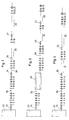
- FIG. 1 A typical fine steel mill for the invention is shown schematically in FIG. 1.
- the street itself is formed by scaffolding 1 to 21; here change horizontal with vertical stands, and only the finishing stand 21 is designed as a universal stand.
- the stands 1 and 2 still rolling rectangular cross sections, while the following stands 3 to 20 Alternate oval and round cross sections effect and the finishing stand 21 also rolled round cross sections.
- the billets to be rolled are preheated to the rolling temperature in the furnace 22.
- a water cooling section 24 is provided between the stands 12 and 13, a water cooling section 25 with a subsequent recovery section 26 is arranged behind the stand 16, and a further water cooling section with a subsequent long recovery section 28 is incorporated behind the stand 18.
- the water cooling section 24 is only effective in special cases, for example when a material is rolled in which higher core temperatures are to be avoided. But the water cooling sections 25 and 27 are already in operation during normal rolling.
- the water cooling section 25 causes pre-cooling, and the actual cooling to the optimum rolling temperature for the finishing batch takes place only in the water cooling section 27; the downstream long recovery section 28 causes a large temperature adjustment of the surface of the rolling stock to the temperature of the core, so that there is a largely homogeneous temperature field within the rolling cross section for the final deformation.
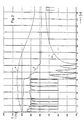
- curves then result, as exemplified diagrammatically in FIG. 2.
- Curve a indicates the core temperature as a function of the path covered within the fine steel mill
- curve b represents the temperature of the surface of the rolling stock
- curve c represents the mean temperature
- the surface of the rolling stock is already cooled as it passes through a stand by direct contact with the cool jackets of the rolls within the forming area.
- the temperature rises due to the conversion of the deformation energy into heat.
- the surface temperature also recovers to a certain extent.
- the surface is cooled by four successive exposures to water, and the surface temperature recovers between the individual cooling units.
- the mean temperature is also reduced; however, an impact on the core temperature only takes place after going through a considerable recovery distance, which is almost too high in the diagram. 80 m length was chosen.
- the average rolling temperature of about 1000 ° before reaching the finishing line is significantly reduced by about 200 °, so that the grain growth is delayed accordingly and after leaving the last stand under the influence of one downstream of the road , further cooling section not taken into account in the figures is further slowed down, so that a fine steel mill equipped in this way and working in accordance with the invention works in the finishing line with a reduced temperature, which provides a fine-grained and excellent mechanical properties starting material.
- the temperature diagram of FIG. 2 illustrates in detail the conditions prevailing when rolling round steel 62 mm mm.
- the stands 1 to 10 of FIG. 1 are in their position shown in FIG. 1, the stands 11 to 20 are extended from the rolling line, and the stands 11 and 12 corresponding to the stands are instead of the stands 19 and 20 Finishing stand 21 arranged upstream.
- Four water cooling sections corresponding to the water cooling sections 25 and 27 are used in the space which has been freed by the extension of the scaffolding 11 to 16; there is also the possibility to use the built-in water cooling sections 24 and 25 and between to install two more water cooling lines.
- the length measurement starts here in the central plane of the scaffold 1.
- the last two spikes of curve b pointing downward now represent the cooling in the stands 11 and 12 in places 19 and 20, and the cooling within the finishing stand 21 is no longer shown in the diagram.
- FIG. 3 Another version of a fine steel mill is shown in FIG. 3.
- horizontal and vertical stands 1 to 20 are alternately provided to achieve the same performance in order to achieve the smallest dimensions to be rolled on the fine steel mill, and the stands 19 effective in the finishing line and 20 is a universal scaffold 21 downstream.
- a cropping shear and a descaling device 34 are arranged upstream of the road, and rotating shears 35 and 36 are provided in the road.
- a transverse transport 29 is provided, offset against the rolling direction, which is capable of picking up billets and feeding the further stands, which are arranged offset, of the fine steel mill.
- This transverse transport is designed in such a way that it can pick up several, for example up to six or up to ten, billets and can hold them in place for cooling over appropriate times, only shifted transversely.
- a longer pre-cooling time can lower undesirably high core temperatures.
- water cooling sections 25 and 27 are provided, each with recreational sections 26 and 28 arranged after them, which operate when the billets are fully rolled out to the smallest cross-sections.
- the finishing stand 21 remains in its place, but is operated with positions or calibres corresponding to the dimensions of the desired finished product.
- the increased drive torque requirement due to the rolling of larger dimensions in the finished group can also be taken into account here by using correspondingly stronger drive motors, comb mill stands, spindles or spindle heads.
- comb stands with different transmission ratios
- comb stands with a selectively effective transmission ratio, or additional transmission stages arranged upstream of the comb rolling stand, so that at predetermined ones Performance an adjustment of the torque given off by the comb rolling mill to the increased torque requirement is possible.
- FIG. 4 Another possibility is explained with reference to FIG. 4.
- the furnace 22, cropping shears and descaling device 34 as well as rotating shears 35 are shown between a number of stands, which in turn was selected for a total of 21.
- the stands 17 and 18, however, have also been incorporated into the finished series, so that when cooling by means of the cooling device 32, the cooling process relates to rolling stock that runs more slowly and can thus be designed more effectively.
- the temperature compensation serving stretch 33 is suitably adapted to the stronger cooling and heat compensation of stronger material.
- the stands 19 and 20 are first removed, and the stands 17 and 18 can move up in their place.
- additional stands are removed from the rolling line, the last still effective stands moving to the positions of stands 19 and 20 or, when changing over four stands, to places 17 to 20.
- the total number of stands to be used for the fine steel mill depends on the smallest cross section to be rolled on this fine steel mill or the highest reduction to be carried out from the incoming semi-finished product to the finished product, whereby an optimal caliber distribution on the rollers must be taken into account as well as an optimization of the Roll diameter on the cross section to be rolled.
- the last of the stands combined to form a finished scale, are used to finish-roll the finished product, and in order to achieve favorable stress values for the finished product, the rolling in the finished scale is brought about at such a reduced temperature that the required drive torques result as a result the temperature-related increase in the forming work of the material can be increased, with a corresponding reduction in the finishing scaffold, preferably in the finishing stand, the resulting trimmer structure of the grain growth that decreases with the reduced rolling temperature is only offered because of this slight grain growth when the austenite is converted to pearlite to get fine-grained, fine-streaked pearlite.
- the cooling of the rolling stock entering the last or the last stands which is essential for achieving an optimal structure, is effected by means of water cooling sections, one of which is arranged upstream of the finishing relay while maintaining a sufficient recovery section.
- the scaffold locations that have become free can be made effective instead of or in addition to the originally intended water cooling sections by equipping the vacant places with the spray devices of the water cooling sections.
- the available recovery section can also be extended, thus achieving better temperature compensation between the core and the outer skin of the rolling stock.
- the water cooling sections are preferably arranged in such a way that they run on round or square cross sections.
- the water cooling sections are preferably provided in the area of the last stands, so that a maximum cooling effect is achieved and, due to the small number of subsequent stands, the smallest rewarming of the rolling stock is achieved due to the deformations that occur. Late cooling has also proven its worth, since with the onset of cooling, the deformation work increases and, on the one hand, the drive is subjected to greater stress, but, on the other hand, the wear on the scaffolding also increases due to stronger forces and moments.
- each of the water cooling sections 25 and 27 is followed by a relaxation section 26 and 28; however, the recovery section 26 initially run is only intended to allow the core temperature to approximate to the outside temperature in order to enable sufficient cooling in the subsequent water cooling section without the surface being undercooled.
- the last of the recreational routes is dimensioned such that the temperature compensation is advanced as desired during the finishing rolling in the finishing season. If the relaxation zones required here become undesirably long, the water cooling sections upstream of them can be moved forward against the rolling direction will.
- the diameter of the rolls can advantageously be minimized since only a narrowly limited cross-sectional area is rolled in each of the stands, except that of the finished group.
- These possible small roll diameters result in a reduced width with a correspondingly increased lengthening of the rolling stock, and consequently only a smaller decrease in height is required in the following stands or an increased reduction is made possible, so that lower rolling forces, lower drive torques and a reduced motor output with a correspondingly reduced Energy consumption can be achieved.
- Since essentially the same cross-sections are reduced in every scaffolding, with the exception of those of the prefabricated structure, any changes to the dimensions of the finished product which are required are also reduced to a minimum. Except for the finished scale, when changing the program it is necessary to extend or retract certain stands, but not to change the rollers.
- cooling is provided within the fine steel mill, which, however, is essentially effected before the finishing relay, and which is followed by a correspondingly long recreational route, in order to achieve a large temperature balance between the inner and the outer to secure outer districts of the rolling stock.
- an additional cooling section with a shorter recovery section can be arranged in front, and for material that is sensitive to an increase in the core temperature, a corresponding upstream cooling device can also be used, which is designed as a water cooling section or as a storing and cooling transport that allows cooling can be.
- it has proven effective not to lower the temperature in the front of the scaffolding in order to be able to drive with the previous drive powers, and to carry out the desired temperature reduction only before the last of the scaffolding.
Landscapes
- Engineering & Computer Science (AREA)
- Mechanical Engineering (AREA)
- Chemical & Material Sciences (AREA)
- Materials Engineering (AREA)
- Crystallography & Structural Chemistry (AREA)
- Thermal Sciences (AREA)
- Physics & Mathematics (AREA)
- Metallurgy (AREA)
- Organic Chemistry (AREA)
- Metal Rolling (AREA)
- Lubricants (AREA)
- Disintegrating Or Milling (AREA)
- Electrochromic Elements, Electrophoresis, Or Variable Reflection Or Absorption Elements (AREA)
Claims (7)
- Train de laminage à fers marchands ou train de laminage pour acier moyen présentant un groupe de départ, au moins un groupe intermédiaire ainsi qu'au moins un groupe finisseur et un four disposé avant ledit train dans lequel on a disposé, après les cages du groupe finisseur, des zones de refroidissement à eau comportant des zones d'équilibrage de la température, caractérisé en ce que, pour le laminage d'aciers au carbone usuels, la zone d'équilibrage (28) disposée après la zone de refroidissement (27) se trouvant avant le dernier groupe des cages (19 à 21) du groupe finisseur présente une longueur garantissant dans une large mesure un équilibrage entra la température du noyau et la température de surface du produit à laminer et en ce que la réduction minimale du groupe finisseur, de préférence de la dernière cage (21), dépasse 19 %.
- Train de laminage à fers marchands selon la revendication 1, caractérisé en ce que d'autres zones de refroidissement (24, 25) sont prévues avant ou dans le groupe intermédiaire.
- Train de laminage à fers marchands selon la revendication 1 ou 2, caractérisé en ce qu'une zone de refroidissement prévue avant ou dans le groupe intermédiaire est exécutée sous forme d'un transport transversal (29).
- Train de laminage à fers marchands selon une quelconque des revendications 1 à 3, caractérisé an ce que, lors de l'adaptation à des sections de départ plus grandes, les deux dernières cages parmi les cages ne participant pas sont enlevées et en ce que ces deux dernières cages sont introduites de manière correspondante dans le groupe finisseur.
- Train de laminage à fers marchands selon une quelconque des revendications 1 à 4, caractérisé en ce que le train finisseur présente une cage à pignons double réversible ou une cage à pignons précédée de démultiplications pouvant être utilisées au choix.
- Train de laminage à fers marchands selon une quelconque des revendications 4 ou 5, caractérisé en ce que les zones libérées par les cages enlevées sont équipées de zones de refroidissement à eau supplémentaires.
- Train de laminage à fers marchands selon une quelconque des revendications 1 à 6, caractérisé par des dispositifs de commande et/ou de réglage des zones de refroidissement (24, 25, 27, 30, 32) qui empêchent le cas échéant le dépassement dos températures maximales prédéfinies du noyau dans les zones de refroidissement disposées avant le groupe finisseur et qui provoquent, grâce à des zones du refroidissement (24, 25) disposées ultérieurement, des propriétés mécaniques et des tailles de particules optimales assurant des températures de laminage sûres pour le groupe finisseur.
Priority Applications (1)
| Application Number | Priority Date | Filing Date | Title |
|---|---|---|---|
| AT87115220T ATE101065T1 (de) | 1986-10-20 | 1987-10-17 | Fein- oder mittelstahlstrasse. |
Applications Claiming Priority (2)
| Application Number | Priority Date | Filing Date | Title |
|---|---|---|---|
| DE8627940 | 1986-10-20 | ||
| DE8627940U | 1986-10-20 |
Publications (3)
| Publication Number | Publication Date |
|---|---|
| EP0264868A2 EP0264868A2 (fr) | 1988-04-27 |
| EP0264868A3 EP0264868A3 (en) | 1989-03-22 |
| EP0264868B1 true EP0264868B1 (fr) | 1994-02-02 |
Family
ID=6799400
Family Applications (1)
| Application Number | Title | Priority Date | Filing Date |
|---|---|---|---|
| EP87115220A Revoked EP0264868B1 (fr) | 1986-10-20 | 1987-10-17 | Laminoir à fers moyens et marchands |
Country Status (3)
| Country | Link |
|---|---|
| EP (1) | EP0264868B1 (fr) |
| AT (1) | ATE101065T1 (fr) |
| DE (1) | DE3788996D1 (fr) |
Cited By (1)
| Publication number | Priority date | Publication date | Assignee | Title |
|---|---|---|---|---|
| DE10032833B4 (de) * | 1999-07-26 | 2010-04-01 | Siemens Vai Metals Technologies Gmbh | Walzwerksanlage |
Families Citing this family (9)
| Publication number | Priority date | Publication date | Assignee | Title |
|---|---|---|---|---|
| DE3830101A1 (de) * | 1988-09-05 | 1990-03-15 | Schloemann Siemag Ag | Verfahren zum betrieb eines stabstahlwalzwerkes mit auf einer walzlinie angeordneter kuehlstrecke zum thermomechanischen fertigwalzen und stabstahlwalzwerk zur durchfuehrung des verfahrens |
| IT1235119B (it) * | 1989-07-10 | 1992-06-18 | Danieli Off Mecc | Gabbia di laminazione con rulli a sbalzo multipli per laminazione veloce. |
| DE4207296A1 (de) * | 1992-03-07 | 1993-09-09 | Schloemann Siemag Ag | Feinstahl/drahtstrasse |
| DE4207298A1 (de) * | 1992-03-07 | 1993-09-09 | Schloemann Siemag Ag | Verfahren und walzwerk zum praezisionswalzen von draht bzw. von walzgut mit rundquerschnitt |
| DE4217149A1 (de) * | 1992-05-23 | 1993-11-25 | Schloemann Siemag Ag | Walzwerk für Draht oder Stabstahl mit einer kontinuierlichen Feinstahl- oder Drahtstraße |
| IT1288849B1 (it) * | 1996-02-12 | 1998-09-25 | Danieli Off Mecc | Procedimento perfezionato per la laminazione di prodotti lunghi e linea di laminazione che realizza detto procedimento |
| DE19806267A1 (de) * | 1997-11-10 | 1999-05-20 | Siemens Ag | Verfahren und Einrichtung zur Steuerung einer hüttentechnischen Anlage |
| IT1391760B1 (it) * | 2008-11-11 | 2012-01-27 | Danieli Off Mecc | Processo di trattamento termico di laminati |
| CN114951316B (zh) * | 2022-06-28 | 2024-12-31 | 山东莱钢永锋钢铁有限公司 | 一种多切分扁料控轧控冷工艺 |
Family Cites Families (10)
| Publication number | Priority date | Publication date | Assignee | Title |
|---|---|---|---|---|
| SE328602B (fr) * | 1962-08-24 | 1970-09-21 | Morgan Construction Co | |
| ES291345A1 (es) * | 1962-08-24 | 1963-11-01 | Morgan Construction Co | Procedimiento para enfriamiento regulado de acero en barras continuas |
| DE1533999A1 (fr) * | 1967-01-17 | 1970-12-10 | ||
| BE709228A (fr) * | 1968-01-11 | 1968-05-16 | ||
| FR2196207A1 (fr) * | 1972-08-18 | 1974-03-15 | Morgan Construction Co | |
| CA1028535A (fr) * | 1973-11-15 | 1978-03-28 | Bethlehem Steel Corporation | Methode de controle thermique au cours du laminage a chaud sur trains continus a chaud |
| DE2602656C2 (de) * | 1975-01-29 | 1986-09-11 | Centre de Recherches Métallurgiques - Centrum voor Research in de Metallurgie - Association sans but lucratif - Vereniging zonder winstoogmerk, Brüssel/Bruxelles | Verfahren zur Herstellung von Walzstahl für Bewehrungszwecke |
| DE2717780B2 (de) * | 1977-04-21 | 1979-11-29 | Hamburger Stahlwerke Gmbh, 2103 Hamburg | Herstellung von Walzdraht |
| DE3039101A1 (de) * | 1980-10-16 | 1982-05-13 | Schloemann-Siemag AG, 4000 Düsseldorf | Anordnung einer kontinuierlich arbeitenden feinstahl-drahtwalzstrasse zum auswalzen von draht oder rundquerschnitten aus edelstaehlen oder hochwertigen legierungen |
| DD236885A1 (de) * | 1985-05-06 | 1986-06-25 | Thaelmann Schwermaschbau Veb | Verfahren zum ueberwachen der walzguttemperatur |
-
1987
- 1987-10-17 AT AT87115220T patent/ATE101065T1/de not_active IP Right Cessation
- 1987-10-17 EP EP87115220A patent/EP0264868B1/fr not_active Revoked
- 1987-10-17 DE DE87115220T patent/DE3788996D1/de not_active Revoked
Cited By (1)
| Publication number | Priority date | Publication date | Assignee | Title |
|---|---|---|---|---|
| DE10032833B4 (de) * | 1999-07-26 | 2010-04-01 | Siemens Vai Metals Technologies Gmbh | Walzwerksanlage |
Also Published As
| Publication number | Publication date |
|---|---|
| EP0264868A3 (en) | 1989-03-22 |
| EP0264868A2 (fr) | 1988-04-27 |
| ATE101065T1 (de) | 1994-02-15 |
| DE3788996D1 (de) | 1994-03-17 |
Similar Documents
| Publication | Publication Date | Title |
|---|---|---|
| DE69125926T2 (de) | System und verfahren zum formen dünner flacher warmgewalzter metallbänder | |
| DE69201993T2 (de) | Verfahren zum kontinuierlichen Warmwalzen langer Stahlprodukte. | |
| DE19518144C2 (de) | Verfahren zum Herstellen von Warmband und kombinierte Stranggieß- und Warmwalz-Anlage | |
| DE69411971T3 (de) | Warmwalzwerk für Stahlblech und Walzverfahren | |
| DE69116981T2 (de) | Kontinuierliches Warmband-Walzsystem | |
| EP2437900B1 (fr) | Train de laminoir économe en énergie et procédé économe en énergie permettant de faire fonctionner une installation combinée de coulée et de laminage | |
| EP0593001B1 (fr) | Méthode et dispositif pour manufacture de tÔles ou poutres laminées à chaud en matière coulée | |
| DE10038292A1 (de) | Produktionsverfahren und -anlage zur Erzeugung von dünnen Flachprodukten | |
| DE3730471A1 (de) | Kompaktwalzwerk und arbeitsverfahren zum walzen von formstahl | |
| DE3830101A1 (de) | Verfahren zum betrieb eines stabstahlwalzwerkes mit auf einer walzlinie angeordneter kuehlstrecke zum thermomechanischen fertigwalzen und stabstahlwalzwerk zur durchfuehrung des verfahrens | |
| EP0264868A2 (fr) | Laminoir à fers moyens et marchands | |
| DE4009861C2 (de) | Verfahren zur Herstellung von warmgewalztem Stangenmaterial wie Feinstahl oder Draht und Anlage zur Durchführung des Verfahrens | |
| DE1452020A1 (de) | Verfahren zum Walzen von Schienenprofilen | |
| DE60314256T2 (de) | Verfahren und anlage zum heisswalzen von schienen | |
| AT410063B (de) | Verfahren und anlage zum walzen von erwärmtem metallischem gut | |
| DE69204545T2 (de) | Verfahren zur Herstellung von Profilen und/oder Stäben im kalten Zustand. | |
| DE2437684C2 (de) | Walzwerk zur Herstellung von Draht und Rippenstahl | |
| EP0560093B1 (fr) | Laminoir à fers marchands et à fil d'acier | |
| DE102013212951A1 (de) | Gießwalzanlage und Verfahren zum Herstellen von metallischem Walzgut | |
| EP0571789B1 (fr) | Laminoir pour fils ou barres avec un train continu à fils ou à barres | |
| EP1463591A1 (fr) | Procede et installation de laminage permettant de produire du fil metallique, des barres ou des tuyaux sans soudure | |
| DE10261632B4 (de) | Verfahren und Walzanlage zum Herstellen von Draht, Stäben oder nahtlosen Rohren | |
| DE3045920A1 (de) | "verfahren und vorrichtung zum walzen von stahlrohlingen" | |
| EP0919296B1 (fr) | Adaption des trains de laminage chauds pour laminer des bandes minces | |
| DE202010018534U1 (de) | Giess- und kontinuierliche Walzanlage zur Herstellung von langen metallischen Walzerzeugnissen |
Legal Events
| Date | Code | Title | Description |
|---|---|---|---|
| PUAI | Public reference made under article 153(3) epc to a published international application that has entered the european phase |
Free format text: ORIGINAL CODE: 0009012 |
|
| 17P | Request for examination filed |
Effective date: 19871106 |
|
| AK | Designated contracting states |
Kind code of ref document: A2 Designated state(s): AT BE DE FR GB IT SE |
|
| PUAL | Search report despatched |
Free format text: ORIGINAL CODE: 0009013 |
|
| AK | Designated contracting states |
Kind code of ref document: A3 Designated state(s): AT BE DE FR GB IT SE |
|
| 17Q | First examination report despatched |
Effective date: 19901016 |
|
| GRAA | (expected) grant |
Free format text: ORIGINAL CODE: 0009210 |
|
| AK | Designated contracting states |
Kind code of ref document: B1 Designated state(s): AT BE DE FR GB IT SE |
|
| PG25 | Lapsed in a contracting state [announced via postgrant information from national office to epo] |
Ref country code: FR Effective date: 19940202 Ref country code: BE Effective date: 19940202 |
|
| REF | Corresponds to: |
Ref document number: 101065 Country of ref document: AT Date of ref document: 19940215 Kind code of ref document: T |
|
| REF | Corresponds to: |
Ref document number: 3788996 Country of ref document: DE Date of ref document: 19940317 |
|
| ITF | It: translation for a ep patent filed | ||
| GBT | Gb: translation of ep patent filed (gb section 77(6)(a)/1977) |
Effective date: 19940506 |
|
| EN | Fr: translation not filed | ||
| PG25 | Lapsed in a contracting state [announced via postgrant information from national office to epo] |
Ref country code: GB Effective date: 19941017 |
|
| PLBI | Opposition filed |
Free format text: ORIGINAL CODE: 0009260 |
|
| 26 | Opposition filed |
Opponent name: DANIELI & C. OFFICINE MECCANICHE SPA Effective date: 19941027 |
|
| EAL | Se: european patent in force in sweden |
Ref document number: 87115220.3 |
|
| GBPC | Gb: european patent ceased through non-payment of renewal fee |
Effective date: 19941017 |
|
| RDAH | Patent revoked |
Free format text: ORIGINAL CODE: EPIDOS REVO |
|
| APAC | Appeal dossier modified |
Free format text: ORIGINAL CODE: EPIDOS NOAPO |
|
| APAE | Appeal reference modified |
Free format text: ORIGINAL CODE: EPIDOS REFNO |
|
| APAC | Appeal dossier modified |
Free format text: ORIGINAL CODE: EPIDOS NOAPO |
|
| PGFP | Annual fee paid to national office [announced via postgrant information from national office to epo] |
Ref country code: AT Payment date: 19990923 Year of fee payment: 13 |
|
| PGFP | Annual fee paid to national office [announced via postgrant information from national office to epo] |
Ref country code: DE Payment date: 19990927 Year of fee payment: 13 |
|
| RAP2 | Party data changed (patent owner data changed or rights of a patent transferred) |
Owner name: SMS DEMAG AG |
|
| APAC | Appeal dossier modified |
Free format text: ORIGINAL CODE: EPIDOS NOAPO |
|
| RDAG | Patent revoked |
Free format text: ORIGINAL CODE: 0009271 |
|
| STAA | Information on the status of an ep patent application or granted ep patent |
Free format text: STATUS: PATENT REVOKED |
|
| PGFP | Annual fee paid to national office [announced via postgrant information from national office to epo] |
Ref country code: SE Payment date: 20001002 Year of fee payment: 14 |
|
| 27W | Patent revoked |
Effective date: 20000718 |
|
| APAH | Appeal reference modified |
Free format text: ORIGINAL CODE: EPIDOSCREFNO |