EP0264921B1 - Convertisseur numérique-analogique - Google Patents
Convertisseur numérique-analogique Download PDFInfo
- Publication number
- EP0264921B1 EP0264921B1 EP87115362A EP87115362A EP0264921B1 EP 0264921 B1 EP0264921 B1 EP 0264921B1 EP 87115362 A EP87115362 A EP 87115362A EP 87115362 A EP87115362 A EP 87115362A EP 0264921 B1 EP0264921 B1 EP 0264921B1
- Authority
- EP
- European Patent Office
- Prior art keywords
- digital
- signal
- bits
- converting
- analog
- Prior art date
- Legal status (The legal status is an assumption and is not a legal conclusion. Google has not performed a legal analysis and makes no representation as to the accuracy of the status listed.)
- Expired - Lifetime
Links
Images


Classifications
-
- H—ELECTRICITY
- H03—ELECTRONIC CIRCUITRY
- H03M—CODING; DECODING; CODE CONVERSION IN GENERAL
- H03M1/00—Analogue/digital conversion; Digital/analogue conversion
- H03M1/66—Digital/analogue converters
- H03M1/68—Digital/analogue converters with conversions of different sensitivity, i.e. one conversion relating to the more significant digital bits and another conversion to the less significant bits
- H03M1/682—Digital/analogue converters with conversions of different sensitivity, i.e. one conversion relating to the more significant digital bits and another conversion to the less significant bits both converters being of the unary decoded type
-
- H—ELECTRICITY
- H03—ELECTRONIC CIRCUITRY
- H03M—CODING; DECODING; CODE CONVERSION IN GENERAL
- H03M1/00—Analogue/digital conversion; Digital/analogue conversion
- H03M1/66—Digital/analogue converters
- H03M1/74—Simultaneous conversion
- H03M1/76—Simultaneous conversion using switching tree
- H03M1/765—Simultaneous conversion using switching tree using a single level of switches which are controlled by unary decoded digital signals
Definitions
- the invention relates to a digital to analog converter, and more particularly to a digital to analog converter in which two digital to analog converting means are provided to produce two analog signals which are then added to be an analog signal.
- One of conventional digital to analog (simply called “D/A” hereinafter) converters comprises a first D/A converting means for converting upper four bits of a eight bit digital signal to a first analog signal, a second D/A converting means for converting lower four bits of the eight bit digital signal to a second analog signal, an attenuator for attenuating the second analog signal by an attenuation factor of 1/24, and an adder for adding the first analog signal and the second analog signal which is attenuated.
- the eight bit digital signal is supplied to the first and second D/A converting means by the upper and lower four bits separately so that the first and second analog signals are produced depending upon the contents of the upper and lower four bits.
- the second analog signal is then attenuated in the attenuator by the attenuation factor of 1/24. Thereafter, the first analog signal and attenuated second analog signal are added so that an analog signal corresponding in its value to the eight bit digital signal is produced.
- outputs of analog data are deteriorated in their characteristic, when inputs of digital data are of a value nearly at the origin 0 of the coordinate axes because such an error as described above is produced.
- the characteristics of S/N ratio or waveform distortion is deteriorated in reproducing audio signal based on a weak power of digital signals.
- US-A-4 412 208 deals with this non-linearity problem and provides a solution consisting of shifting the digital input. Furthermore, EP-A-0 065 795 describes a digital to analog converter comprising means for adding a predetermined value (00000101) to a digital 8-bit signal in order to improve the signal-to-noise ratio in the vicinity of the zero level.
- DE-A-3 215 519 discloses a single D/A converter in which the digital input is also shifted and which comprises an overflow detector; however, this D/A converter is not divided in upper and lower blocks.
- the conventional digital to analog converter comprises a first D/A converting means 11 for converting upper four bits of an eight bit digital signal to be supplied to input terminals A4 to A7 to a first analog signal, a second D/A converting means 12 for converting lower four bits of the eight bit digital signal to be supplied to input terminals A0 to A3 to a second analog signal, an attenuator 13 for attenuating the second analog signal by an attenuation factor of 1/24 such that a scaling is performed between the first and second D/A converting means, and an adder 14 for adding the first analog signal and attenuated second analog signal to produce an analog signal at an output terminal 0 1 thereof.
- the first analog signal corresponding to the upper four bits of the digital signal is produced in the first D/A converting means 11, while the second analog signal corresponding to the lower four bits of the digital signal is produced in the second D/A converting means 12.
- the second analog signal which is supplied from the second D/A converting means 12 is attenuated in the attenuator 13 by the attenuating factor factor 1/24 because the second analog signal must be of 1/24 in regard to the first signal.
- the first analog signal and attenuated second signal are added in the adder 14 to produce the analog signal at the ouput terminal 0 1.
- the error is resulted from an error of steps based on a difference of characteristics between the first and second D/A converting means 11 and 12, for instance, in a case where the digital inputs are changed from "0111” to "1000" in the first D/A converting means 11, and from "1111” to "0000" in the second D/A converting means 12, when a signal is changed from "-1" to "0", that is, the digital input is changed from "01111111” to "10000000".
- Fig. 2A the errors are produced where a scaling of the first D/A converting means 11 is slightly bigger than that of the second D/A converting means 12.
- the errors are produced in Fig. 2B where the scaling of the second D/A converting means 12 is slightly bigger than that of the first D/A converting means 11.
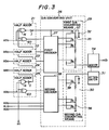
- the digital to analog converter comprises half adders 21 to 25, a D/A converting unit 26, an attenuator 31, and an adder 34.
- Each of the half adders 21 to 25 includes an exclusive OR circuit EO which is connected to one of input terminals A3 to A7, a NAND circuit N which is also connected to one of the input terminals A3 to A7, and an inverter I which is connected to the output terminal of the NAND circuit N.
- each of the half adders 22 to 25 the output of the inverter I is applied to remaining inputs of the exclusive OR circuit EO and NAND circuit N in a following half adder, while the output of the inverter I of the half adder 21 is supplied to the D/A converting unit 26.
- the control signal "high" is applied to one of the inputs of the NAND circuit N from a control terminal H1.
- the D/A converting unit 26 includes first and second decoders 27 and 28, and first and second D/A converting means 29 and 30.
- the first decoder 27 is connected to the respective exclusive OR circuits EO of the half adders 21 to 24 and to the inverter I of the half adder 21, while the second decoder 28 is connected to the exclusive OR circuit of the half adder 25 and to input terminals A0 to A2.
- the first D/A converting means 29 includes a DC voltage source 32, sixteen of resistances 35, and seventeen of transistors 37, while the second D/A converting means 30 includes a DC voltage source 33, fifteen of resistance 36, and sixteen of transistors 38.
- the lower sixteen of the transistor 37 are connected to the output terminals of the first decoder 27, while the remaining one of the transistors 37 is connected to the inverter I of the half adder 21.
- the common connecting point of the transistors 37 is connected to the adder 34 having an output terminal 0 1.
- the transistors 38 are connected to the respective output terminals of the second decoder 28.
- the common connecting point of the transistors 38 is connected to the input of the attenuator 31 which is connected to the adder 34 at the output thereof.
- digital data which are applied to the input terminals A0 to A7 and fixed digital data "1000" (binary) based on the control signal applied to the control terminal H1 are added to produce a nine bit digital signal wherein a highest bit thereof is supplied to the first decoder 27, and to the corresponding one of the transistors 37 of the first D/A, converting means 29, the middle four bits thereof are supplied from the half adders 21 to 24 to the first decoder 27, and the lower four bits thereof are supplied from the half adder 25 and input terminals A0 to A2 to the second decoder 28.
- each of the first and second decoders 27 and 28 one of output terminals thereof is selected to be "high” dependent on a content of input bits so that the respective ones of transistors 37 and 38 are turned on in each of the first and second D/A converting means 29 and 30.
- the first decoder 27 none of the output terminals is selected, when the output of the inverter I is "high" in the half adder 21.
- a first analog signal which is one of seventeen analog values in the first D/A converting means 29 is produced to be supplied to the adder 34
- a second analog signal which is one of sixteen analog values in the second D/A converting means 30 is produced to be supplied to the attenuator 31.
- the second analog signal is attenuated in the attenuator 31 by a attenuating factor of 1/24.
- the first analog signal and second analog signal thus attenuated are added to produce an analog signal at the output terminal 0 1.
- the fixed value "1000" is added to the digital data applied to the input terminals A0 to A3 so that the origin 0 of the coordinate axes X and Y is shifted to the origin 0' as shown in Figs. 2A and 2B.
- Figs. 2A and 2B there is substantially occured no error at the shifted origin 0' or in the vicinity thereof so that the characteristic of S/N ratio or distortion of waveform can be improved.
- Fig. 4 shows a D/A converting means which can be in place of the first decoder 27 and first D/A converting means 29 in Fig. 3.
- the D/A converting means comprises input terminals B4 to B8 which are connected to the output terminals of the half adders 22 to 25 and two output terminals of the half adder 21 in Fig.
- OR circuits 41 to 44 which are connected to the input terminals B4 to B7 respectively and to the input terminal B8, transistors 454 to 458 which are turned on by outputs of the OR circuits 41 to 44 and signal of the input terminal B8 respectively, current sources 464 to 468 which produces fixed current values of I, 2I, 4I, 8I and I respectively, and a DC voltage sources 47 from which a predetermined DC voltage is applied to the current sources 464 to 468.
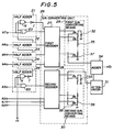
- Fig. 5 shows a digital to analog converter in the second embodiment according to the invention wherein like reference numerals indicate like parts as shown in Fig. 3.
- the digital to analog converter is different from one in the first embodiment only in the construction that the first decoder 27 is provided with five input terminals and thirty-two output terminals in the second embodiment. Accordingly, the output of the inverter I is supplied to the decoder 27, and thirty-two of the transistor 37 are provided in the first D/A converting means 29.
Landscapes
- Engineering & Computer Science (AREA)
- Theoretical Computer Science (AREA)
- Analogue/Digital Conversion (AREA)
Claims (5)
- Convertisseur numérique/analogique comprenant un premier moyen de conversion numérique/analogique (29) pour convertir les bits de poids fort d'un signal numérique commandé en un premier signal analogique, les bits de poids fort étant un groupe supérieur de deux groupes en lequel le signal numérique commandé est divisé,
un second moyen de conversion numérique/analogique (30) pour convertir les bits de poids faible du signal numérique commandé en un second signal analogique, les bits de poids faible étant le groupe inférieur des deux groupes,
un moyen (31) pour atténuer le second signal analogique par un facteur d'atténuation prédéterminé fonction du nombre des bits de poids faible afin de produire un signal analogique atténué, et
un moyen (34) pour produire un signal analogique de sortie en conformité avec l'addition du premier signal analogique et du second signal analogique atténué, caractérisé par
un moyen (21 à 25) pour additionner une valeur numérique prédéterminée à un signal d'entrée numérique pour produire le signal numérique commandé, le nombre des bits de poids fort étant supérieur de un à celui des bits de poids faible,
dans lequel la conversion numérique/analogique est effectuée par les premier et second moyens de conversion numérique/analogique (29, 30) après addition de la valeur numérique prédéterminée,
la valeur numérique prédéterminée étant sélectionnée pour être le centre de l'échelle pleine du second moyen de conversion numérique/analogique (30), et
dans lequel le premier moyen de conversion numérique/analogique (29) comporte des éléments de conversion (35, 37) qui sont d'un nombre supérieur de un à ceux (36, 38) du second moyen de conversion numérique/analogique (30). - Convertisseur numérique/analogique selon la revendication 1, dans lequel le moyen pour l'addition (21 à 25) comporte un demi-additionneur (25) qui est relié à une borne d'entrée (A3) pour le bit de poids fort des bits de poids faible, et des demi-additionneurs (21 à 24) qui sont reliés aux bornes d'entrée pour tous les bits de poids fort (A4 à A7) d'une manière telle qu'un signal de report du demi-additionneur (25) pour les bits de poids faible est appliqué à un (24) des demi-additionneurs qui est destiné au bit de poids faible des bits de poids fort, les signaux de report des demi-additionneurs sont appliqués à un des demi-additionneurs pour un bit de poids fort des bits de poids fort par un bit successif, d'où il résulte qu'une sortie du demi-additionneur (25) des bits de poids faible et les signaux numériques des bornes d'entrée (A₀ à A₂), excluant le bit de poids fort des bits de poids faible, sont appliqués aux moyens (28, 30) pour convertir les bits de poids faible, et les sorties des demi-additionneurs (21 à 24) des bits de poids fort et un signal de report d'un (21) des demi-additionneurs qui est destiné au bit de poids fort des bits de poids fort sont appliqués aux moyens (27, 29) pour convertir les bits de poids fort.
- Convertisseur numérique/analogique selon la revendication 1, dans lequel
le moyen (27, 29) pour convertir les bits de poids fort comporte un décodeur (27) pour décoder les bits de poids fort excluant son bit de poids fort pour produire un premier signal décodé, et un moyen de conversion numérique/analogique (29) pour produire le premier signal analogique en conformité avec le premier signal décodé et le bit le plus significatif des bits de poids fort, et
un moyen (28, 30) pour convertir les bits de poids faible comporte un décodeur (28) pour décoder les bits de poids faible afin de produire un second signal décodé, et un moyen de conversion numérique/analogique (30) pour produire le second signal analogique en conformité avec le second signal décodé. - Convertisseur numérique/analogique selon la revendication 1, dans lequel le premier moyen de conversion numérique/analogique (29) destiné à convertir les bits de poids fort comporte une multitude de sources de courant (46₄ à 46₈) d'un nombre égal aux bits de poids fort, la multitude des sources de courant étant rendue conductrice conformément à la valeur des bits de poids fort et l'intensité du courant de celles-ci étant prédéterminée fonction de la position ou de l'emplacement eu égard aux bits de poids fort.
- Convertisseur numérique/analogique selon la revendication 1, dans lequel le nombre de bits de poids fort est accru d'un bit,
le moyen pour convertir les bits de poids fort comporte un décodeur pour décoder les bits de poids fort afin de produire un signal décodé, et un moyen de conversion numérique/analogique pour produire le premier signal analogique en conformité avec le signal décodé.
Applications Claiming Priority (2)
| Application Number | Priority Date | Filing Date | Title |
|---|---|---|---|
| JP250096/86 | 1986-10-21 | ||
| JP61250096A JPH0738585B2 (ja) | 1986-10-21 | 1986-10-21 | デジタル/アナログ変換装置 |
Publications (3)
| Publication Number | Publication Date |
|---|---|
| EP0264921A2 EP0264921A2 (fr) | 1988-04-27 |
| EP0264921A3 EP0264921A3 (en) | 1990-05-23 |
| EP0264921B1 true EP0264921B1 (fr) | 1993-03-10 |
Family
ID=17202751
Family Applications (1)
| Application Number | Title | Priority Date | Filing Date |
|---|---|---|---|
| EP87115362A Expired - Lifetime EP0264921B1 (fr) | 1986-10-21 | 1987-10-20 | Convertisseur numérique-analogique |
Country Status (4)
| Country | Link |
|---|---|
| US (1) | US4868571A (fr) |
| EP (1) | EP0264921B1 (fr) |
| JP (1) | JPH0738585B2 (fr) |
| DE (1) | DE3784617T2 (fr) |
Families Citing this family (32)
| Publication number | Priority date | Publication date | Assignee | Title |
|---|---|---|---|---|
| JP2683705B2 (ja) * | 1988-10-27 | 1997-12-03 | ナカミチ株式会社 | ディジタル/アナログ変換装置 |
| US5072358A (en) * | 1990-03-09 | 1991-12-10 | Daytronic Corporation | Process controller |
| US4998108A (en) * | 1990-07-30 | 1991-03-05 | International Business Machines Corporation | Large range, high speed, high accuracy digital-to-analog converter |
| JPH0760301B2 (ja) * | 1992-12-02 | 1995-06-28 | 日本電気株式会社 | 液晶駆動回路 |
| JPH09270707A (ja) * | 1996-04-03 | 1997-10-14 | Rohm Co Ltd | ディジタル/アナログ変換器及びそれを用いた制御装置 |
| US5703587A (en) * | 1996-04-19 | 1997-12-30 | Lsi Logic Corporation | Digital-to-analog converter having overlapping segments |
| JP3449254B2 (ja) * | 1997-11-14 | 2003-09-22 | ヤマハ株式会社 | D/a変換装置 |
| FI105622B (fi) * | 1998-02-06 | 2000-09-15 | Nokia Networks Oy | Menetelmä suuren erottelukyvyn digitaali/analogia-muunnoksen suorittamiseksi ja digitaali/analogia-muunnin |
| US6198419B1 (en) * | 1998-06-17 | 2001-03-06 | Lucent Technologies, Inc. | Method and apparatus for extending the spurious free dynamic range of a digital-to-analog converter |
| JP2000172094A (ja) * | 1998-12-07 | 2000-06-23 | Fujitsu Ltd | 転写電流の制御方法と制御回路及びかかる制御回路を備えたプリンタ |
| DE10021824C2 (de) * | 1999-05-07 | 2002-01-31 | Yamaha Corp | D/A-Wandlervorrichtung und D/A-Wandlerverfahren |
| US7095348B1 (en) | 2000-05-23 | 2006-08-22 | Marvell International Ltd. | Communication driver |
| US7113121B1 (en) | 2000-05-23 | 2006-09-26 | Marvell International Ltd. | Communication driver |
| US7312739B1 (en) | 2000-05-23 | 2007-12-25 | Marvell International Ltd. | Communication driver |
| US7194037B1 (en) | 2000-05-23 | 2007-03-20 | Marvell International Ltd. | Active replica transformer hybrid |
| US6775529B1 (en) | 2000-07-31 | 2004-08-10 | Marvell International Ltd. | Active resistive summer for a transformer hybrid |
| US7433665B1 (en) | 2000-07-31 | 2008-10-07 | Marvell International Ltd. | Apparatus and method for converting single-ended signals to a differential signal, and transceiver employing same |
| USRE41831E1 (en) | 2000-05-23 | 2010-10-19 | Marvell International Ltd. | Class B driver |
| US6462688B1 (en) | 2000-12-18 | 2002-10-08 | Marvell International, Ltd. | Direct drive programmable high speed power digital-to-analog converter |
| US7606547B1 (en) | 2000-07-31 | 2009-10-20 | Marvell International Ltd. | Active resistance summer for a transformer hybrid |
| DE10153309B4 (de) * | 2001-10-29 | 2009-12-17 | Infineon Technologies Ag | Digital-Analog-Umsetzer-Vorrichtung mit hoher Auflösung |
| US7312662B1 (en) | 2005-08-09 | 2007-12-25 | Marvell International Ltd. | Cascode gain boosting system and method for a transmitter |
| US7577892B1 (en) | 2005-08-25 | 2009-08-18 | Marvell International Ltd | High speed iterative decoder |
| JP4654857B2 (ja) * | 2005-09-26 | 2011-03-23 | ソニー株式会社 | Da変換装置、ad変換装置、半導体装置 |
| EP1775838B9 (fr) * | 2005-10-11 | 2010-03-03 | Infineon Technologies AG | Correction des erreurs de désadaptation dans un convertisseur N/A |
| KR100850311B1 (ko) * | 2007-03-14 | 2008-08-04 | 삼성전기주식회사 | 디지털/아날로그 컨버터 |
| JP2009079389A (ja) * | 2007-09-25 | 2009-04-16 | Panasonic Electric Works Co Ltd | 雨水取出器 |
| DE102010044028A1 (de) * | 2010-11-17 | 2012-05-24 | Sensordynamics Gmbh | Elektronische Schaltungsanordnung zum Empfangen niederfrequenter elektromagnetischer Wellen mit einem einstellbaren Dämpfungsglied |
| US9590648B2 (en) * | 2014-11-07 | 2017-03-07 | John Howard La Grou | Multi-path digital-to-analog converter |
| US9871530B1 (en) | 2016-12-11 | 2018-01-16 | John Howard La Grou | Multi-path analog-to-digital and digital-to-analog conversion of PDM signals |
| US10256782B2 (en) | 2017-04-25 | 2019-04-09 | John Howard La Grou | Multi-path power amplifier |
| KR102619757B1 (ko) | 2020-04-28 | 2023-12-29 | 레이크 쇼어 크라이오트로닉스 인코포레이티드 | 다중-범위 재료 측정들에서 천이 효과들을 감소시키기 위한 레인징 시스템들 및 방법들 |
Family Cites Families (7)
| Publication number | Priority date | Publication date | Assignee | Title |
|---|---|---|---|---|
| US4412208A (en) * | 1980-09-16 | 1983-10-25 | Nippon Telegraph & Telephone Public Corporation | Digital to analog converter |
| DE3215519A1 (de) * | 1981-04-27 | 1982-11-11 | Hitachi, Ltd., Tokyo | Digital-analog-wandler und/oder analog-digital-wandler |
| JPS57180229A (en) * | 1981-04-30 | 1982-11-06 | Hitachi Ltd | Digital-to-analog converter |
| NL8102226A (nl) * | 1981-05-07 | 1982-12-01 | Philips Nv | Digitaal analoog omzetter voor bipolaire signalen. |
| JPS58215128A (ja) * | 1982-06-09 | 1983-12-14 | Hitachi Ltd | デイジタル・アナログ変換回路 |
| JPS6083423A (ja) * | 1983-10-14 | 1985-05-11 | Nec Ic Microcomput Syst Ltd | D/a変換装置 |
| JPS61159827A (ja) * | 1984-12-31 | 1986-07-19 | Teac Co | ディジタル―アナログ変換方法 |
-
1986
- 1986-10-21 JP JP61250096A patent/JPH0738585B2/ja not_active Expired - Fee Related
-
1987
- 1987-10-20 DE DE8787115362T patent/DE3784617T2/de not_active Expired - Lifetime
- 1987-10-20 EP EP87115362A patent/EP0264921B1/fr not_active Expired - Lifetime
- 1987-10-21 US US07/110,824 patent/US4868571A/en not_active Expired - Fee Related
Also Published As
| Publication number | Publication date |
|---|---|
| JPH0738585B2 (ja) | 1995-04-26 |
| DE3784617D1 (de) | 1993-04-15 |
| EP0264921A2 (fr) | 1988-04-27 |
| JPS63104523A (ja) | 1988-05-10 |
| DE3784617T2 (de) | 1993-07-15 |
| US4868571A (en) | 1989-09-19 |
| EP0264921A3 (en) | 1990-05-23 |
Similar Documents
| Publication | Publication Date | Title |
|---|---|---|
| EP0264921B1 (fr) | Convertisseur numérique-analogique | |
| JP3039791B2 (ja) | Daコンバータ | |
| US5243347A (en) | Monotonic current/resistor digital-to-analog converter and method of operation | |
| US4412208A (en) | Digital to analog converter | |
| US5870044A (en) | Digital analog converter with self-calibration current sources | |
| US4338592A (en) | High accuracy digital-to-analog converter and transient elimination system thereof | |
| US5231398A (en) | Method and apparatus for self-tracking multiple analog to digital conversion | |
| US4695826A (en) | High accuracy digital-to-analog converter having symmetrical current source switching | |
| EP0325378B1 (fr) | Convertisseur numérique-analogique | |
| US4818996A (en) | Digital-to-analog converting circuit | |
| US5640162A (en) | Digital-to-analog converter with binary coded inputs to produce a plurality of outputs in the form of thermometer code | |
| US5017918A (en) | Method and circuit for eliminating major bit transition error at the bipolar zero point in a digital-to-analog converter | |
| US4580131A (en) | Binarily weighted D to a converter ladder with inherently reduced ladder switching noise | |
| JPH0712150B2 (ja) | ディジタル・アナログ変換器 | |
| US4931796A (en) | Digital-to-analog conversion circuit | |
| EP0186757A2 (fr) | Modulateur et démodulateur d'amplitude en quadrature de phase | |
| JPH07106967A (ja) | アナログ・デジタル変換器 | |
| US4782323A (en) | Technique for maintaining a common centroid in switched element analog-to-digital converters | |
| EP0177909A2 (fr) | Convertisseur numérique-analogique | |
| EP0444890B1 (fr) | Convertisseur analogique-numérique intégralement parallèle | |
| JPS58215128A (ja) | デイジタル・アナログ変換回路 | |
| JPS60105322A (ja) | デイジタル−アナログ変換器 | |
| JP2614846B2 (ja) | 誤り補正方法 | |
| JPS6232724A (ja) | A/d変換器 | |
| JPH0473329B2 (fr) |
Legal Events
| Date | Code | Title | Description |
|---|---|---|---|
| PUAI | Public reference made under article 153(3) epc to a published international application that has entered the european phase |
Free format text: ORIGINAL CODE: 0009012 |
|
| 17P | Request for examination filed |
Effective date: 19871020 |
|
| AK | Designated contracting states |
Kind code of ref document: A2 Designated state(s): DE FR GB |
|
| PUAL | Search report despatched |
Free format text: ORIGINAL CODE: 0009013 |
|
| AK | Designated contracting states |
Kind code of ref document: A3 Designated state(s): DE FR GB |
|
| 17Q | First examination report despatched |
Effective date: 19910627 |
|
| GRAA | (expected) grant |
Free format text: ORIGINAL CODE: 0009210 |
|
| AK | Designated contracting states |
Kind code of ref document: B1 Designated state(s): DE FR GB |
|
| REF | Corresponds to: |
Ref document number: 3784617 Country of ref document: DE Date of ref document: 19930415 |
|
| ET | Fr: translation filed | ||
| PLBE | No opposition filed within time limit |
Free format text: ORIGINAL CODE: 0009261 |
|
| STAA | Information on the status of an ep patent application or granted ep patent |
Free format text: STATUS: NO OPPOSITION FILED WITHIN TIME LIMIT |
|
| 26N | No opposition filed | ||
| REG | Reference to a national code |
Ref country code: GB Ref legal event code: IF02 |
|
| REG | Reference to a national code |
Ref country code: GB Ref legal event code: 732E |
|
| REG | Reference to a national code |
Ref country code: FR Ref legal event code: TP |
|
| PGFP | Annual fee paid to national office [announced via postgrant information from national office to epo] |
Ref country code: DE Payment date: 20061012 Year of fee payment: 20 |
|
| PGFP | Annual fee paid to national office [announced via postgrant information from national office to epo] |
Ref country code: GB Payment date: 20061018 Year of fee payment: 20 |
|
| REG | Reference to a national code |
Ref country code: GB Ref legal event code: PE20 |
|
| PG25 | Lapsed in a contracting state [announced via postgrant information from national office to epo] |
Ref country code: GB Free format text: LAPSE BECAUSE OF EXPIRATION OF PROTECTION Effective date: 20071019 |
|
| PGFP | Annual fee paid to national office [announced via postgrant information from national office to epo] |
Ref country code: FR Payment date: 20061010 Year of fee payment: 20 |