EP0264935A2 - Automatisches Heizgerät mit Ultraschalldetektor - Google Patents
Automatisches Heizgerät mit Ultraschalldetektor Download PDFInfo
- Publication number
- EP0264935A2 EP0264935A2 EP87115454A EP87115454A EP0264935A2 EP 0264935 A2 EP0264935 A2 EP 0264935A2 EP 87115454 A EP87115454 A EP 87115454A EP 87115454 A EP87115454 A EP 87115454A EP 0264935 A2 EP0264935 A2 EP 0264935A2
- Authority
- EP
- European Patent Office
- Prior art keywords
- heating
- ultrasonic sensor
- basis
- turntable
- appliance
- Prior art date
- Legal status (The legal status is an assumption and is not a legal conclusion. Google has not performed a legal analysis and makes no representation as to the accuracy of the status listed.)
- Granted
Links
Images


Classifications
-
- H—ELECTRICITY
- H05—ELECTRIC TECHNIQUES NOT OTHERWISE PROVIDED FOR
- H05B—ELECTRIC HEATING; ELECTRIC LIGHT SOURCES NOT OTHERWISE PROVIDED FOR; CIRCUIT ARRANGEMENTS FOR ELECTRIC LIGHT SOURCES, IN GENERAL
- H05B6/00—Heating by electric, magnetic or electromagnetic fields
- H05B6/64—Heating using microwaves
- H05B6/6408—Supports or covers specially adapted for use in microwave heating apparatus
- H05B6/6411—Supports or covers specially adapted for use in microwave heating apparatus the supports being rotated
-
- H—ELECTRICITY
- H05—ELECTRIC TECHNIQUES NOT OTHERWISE PROVIDED FOR
- H05B—ELECTRIC HEATING; ELECTRIC LIGHT SOURCES NOT OTHERWISE PROVIDED FOR; CIRCUIT ARRANGEMENTS FOR ELECTRIC LIGHT SOURCES, IN GENERAL
- H05B6/00—Heating by electric, magnetic or electromagnetic fields
- H05B6/64—Heating using microwaves
- H05B6/6447—Method of operation or details of the microwave heating apparatus related to the use of detectors or sensors
- H05B6/6458—Method of operation or details of the microwave heating apparatus related to the use of detectors or sensors using humidity or vapor sensors
-
- H—ELECTRICITY
- H05—ELECTRIC TECHNIQUES NOT OTHERWISE PROVIDED FOR
- H05B—ELECTRIC HEATING; ELECTRIC LIGHT SOURCES NOT OTHERWISE PROVIDED FOR; CIRCUIT ARRANGEMENTS FOR ELECTRIC LIGHT SOURCES, IN GENERAL
- H05B6/00—Heating by electric, magnetic or electromagnetic fields
- H05B6/64—Heating using microwaves
- H05B6/6447—Method of operation or details of the microwave heating apparatus related to the use of detectors or sensors
- H05B6/6464—Method of operation or details of the microwave heating apparatus related to the use of detectors or sensors using weight sensors
Definitions
- the present invention relates generally to automatic heating appliances, and more particularly to an automatic heating appliance for controlling heating by recognizing, or discriminating, the distinctive feature of an object of be heated with an ultrasonic sensor.
- a heating appliance in which the heating time period is automatically controlled is a microwave oven in which the cooking time period is controlled using a humidity sensor or a gas sensor for detecting vaper or various gases generated from the heated food.
- heating apparatus of the types in which the temperature of the surface of a food is detected by means of an infrared sensor, in which the weight of a food is detected by a weight sensor and in which the both of the surface temperature and food weight are detected thereby.
- the heating control can be performed under the condition that the kind, or class, of an object and the category of cooking are inputted, for example, through keys on an operating panel. That is, the finishing temperature of the object is varied in accordance with the category of cooking.
- the heating time period to be taken is also varied in accordance with the kind of material. Since the prior sensors cannot detect the category of cooking and the kind of material, the heating appliance requires instructions in terms of the cooking category and the kind of food material for automation of the cooking. The inputting thereof is troublesome and hence a further improvement would be required from the viewpoint of simplification of handling of the apparatus.
- a feature of the present invention is that the heating condition of an object to be heated is determined on the basis of the data from an ultrasonic sensor which is arranged to measure the distance to the object and a heating time period is controlled in accordance with the heating condition.
- a heating appliance with a heating chamber comprising: heating means for heating an object which is encased in said heating chamber; turntable means provided in said heating chamger and arranged to be rotatable about its own axis, said object being placed on said turntable means and being rotated in accordance with rotation of said turntable means; ultrasonic sensor means for transmitting an ultrasonic wave toward said object and receiving an echo wave returning therefrom; and control means for controlling said ultrasonic sensor means so as to successively calculate the distances of said object from said ultrasonic sensor means on the basis of the transmission and reception of the ultrasonic wave, said control means determining the heating condition of said object on the basis of the successively calculated distances and controlling said heating means in accordance with the result of the determination.
- a heating appliance with a heating chamber comprising: heating means for heating an object which is encased in said heating chamber; turntable means provided in said heating chamger and arranged to be rotatable about its own axis, said object being placed on said turntable means and being rotated in accordance with rotation of said turntable means; ultrasonic sensor means for transmitting an ultrasonic wave toward said object and receiving an echo wave returning therefrom; weight sensor means for sensing the weight of said object placed on said turntable means; and control means for controlling said ultrasonic sensor means so as to successively calculate the distances of said object from said ultrasonic sensor means on the basis of the transmission and reception of the ultrasonic wave, said control means determining the volume of said object on the basis of the successively calculated distances and calculating the density of said object on the basis of the determined volume and the weight sensed by said weight sensor, said control means controlling said heating means in accordance with the calculated density of said object.
- FIG. 1 there is illustrated the arrangement of an automatic heating appliance according to an embodiment of the present invnetion.
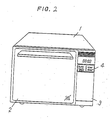
- a heating instruction is transmitted to a control section 5 through a keyboard 4 on an operating panel 3 which are illustrated in Fig. 2 which is a perspective view showing the external appearance of the automatic heating appliance according to the embodiment of the invention and wherein numerals 1 and 2 represent a housing and a door, respectively.
- the control section 5 may comprising a known microcomputer with a central processing unit (CPU) and memories, energizes an ultrasonic sensor 6, provided on the ceiling of a heating chamber 7, so that the ultrasonic sensor 6 emitts an ultrasonic wave downwardly to measure the distance d to an object 9, to be heated, placed on a turntable 8 by reception of an echo wave returning from the object 9, which is positioned below the ultrasonic sensor 6.
- the ultrasonic sensor 6 is driven through a drive and detection circuit 12 and the signal indicative of the distance data is supplied therethrough to the control section 5.
- a weight sensor 10 for measuring the weight of the object 9, which is coupled to the drive shaft of the turntable 8.
- the weight data is supplied through a detection circuit 13 to the control section 5.
- the weight sensor 10 may be of one of known various types, for example, in which the displacement of the turntable 8 is detected as the variation of electric capacity, the detection circuit 13 will be arranged in accordance with the type of the weight sensor so as to generate a signal corresponding to the detected weight.
- the weight sensor 10 is preferably used for the purposes of calculating the heating time period on thawing of a frozen food and so on and further, in this embodiment, of obtaining the density of the object 9 by working together with the ultrasonic sensor 6.
- the control section 5 starts to supply power through a driver 15 to a heater 14 with a magnetron which in turn generates a heat.
- a cooling fan 40 is driven to cool the magnetron of the heater 14 and the cooling air is introduced through an intake guide 16 into the heating chamber 7 which is in turn ventilated.
- the introduced air is exhausted through an exhaust guide 17 to the outside.
- a gass sensor 18 for detecting the vaper and various gasses generated from the heated object 9.
- the gas sensor 18 can be used the relative humidity sensor "HUMISERAM” or the absolute humidity sensor “NEO HUMISERAM” made by Matshshita Electric Industrial Co., Ltd, for example.
- the gas data of the gas sensor 18 is supplied through a detection circuit 19 to the control section 5.
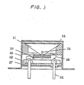
- Fig. 3 is a cross-sectional view showing one example of the ultrasonic sensor 6, i.e, a narrow super directional ultrasonic microphone.
- the ultrasonic sensor 6 comprises a piezoelectric device 20, a conically shaped resonator 21, a terminal 22, bean shaping plate 23, a case 24, lead lines 25, a coup]ling shaft 26, a terminal plate 27 and an aciustic absorption sheet 28, the detailed arrangement thereof being disclosed in "National Technical Report" Vol. 29, pages 504 to 514, January 1983.
- Fig. 4 is an illustration of the shapes of heating objects detected using the ultrasonic sensor 6, wherein the horizontal axis represents the position (rotational angle) of the turntable 8 and the vertical axis represents the height of the heating objects. Shadowed portions represent the revolved cross sections of two objects, for example, spinach and potato, with respect to the rotating center apart by l (Fig. 1) from the ultrasonic sensor 6.
- the entire shape of the object 9 can be estimated, under the condition that the ultrasonic sensor 6 is positioned appropriately.
- the weight data of the object 9 is further obtained in addition to the entire shape, i.e., volume, the class of the object 9 can be estimated.
- the classes thereof can be estimated on the basis of the difference between weights thereof.
- the control section 5 calculates the density of the object 9 by dividing the area, or volume, of the revolved cross-section thereof by the detected weight thereof and determines the class of the object 9 on the basis of the calculated density using a look-up table, or map, stored in a memory (ROM) of the control section 5.
- Fig. 5 is a block diagram showing the arrangement of the drive and detection circuit 12 coupled to the control section 5.
- the drive and detection circuit 12 comprises a transmitting circuit 29 and a receiving circuit 30.
- the transmitting circuit 29 drives the ultrasonic sensor 6 in response to a timing control signal from the control section 5 and the receiving circuit 30 receives an output signal of the ultrasonic sensor 6 corresponding to the echo wave returning from the object 9.
- the output signal of receiving circuit 30 is supplied to a comparator 31 where the output signal of the receiving circuit 30 is compared with a reference voltage. If the output signal exceeds the reference voltage, the output signal is latched and supplied to the control section 5.
- the control section 5 counts the time period from the transmission to the reception and calculates the distance to the object 9 on the basis of the propagating speed of ultrasonic wave and then to calculates the height of the object 9 in accordance with the above-mentioned equation.
- the gas sensor 18 and the detection circuit 19 may realized in accordaqnce with Japanese Patent Provisional Publication No. 51-134951, for example. Therefore, the description of the arrangement and control method thereof will be omitted for brevity.
- the class of the object 9 can be determined and the heating time can be desirably controlled on the basis of the determined class.
- the class of the object 9 is estimated on the basis of its weight and volume, it is possible to estimate the class thereof only on the basis of the data from the ultrasonic sensor 6.
- the weight data may be additionally used for the discrimination.
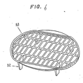
- Fig. 6 shows an attachment, disclosed in Japanese Patent Provisional Publication No. 58-43329, used on thawing cooking, which is made of a resin and which comprises leg portions 32 and a net portion 33.
- the attachment is generally used in thawing operation for the purposes of dropping down water droplets or gravy from a frozen food upto the turntable 8 to allow the food to be separated from the water or gravy.
- the thawing is determined in accordance with the presence or absence of the attachment.
- the detection of the category of cooking will be described hereinbelow with reference to Figs. 7 to 9.
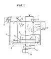
- Fig. 7 shows the case that a frozen food placed on the Fig. 6 attachment 34 is thawed.
- the detected height of the object 9 becomes higher by the height of the attachment as compared with the case of not employing the attachment 34.
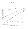
- the attachment is light in weight because it is made in the leg structure and of a resin, and therefore it is possible to determine the presence or absence of the attachment 34 in accordance with the relationship between the weight detected by the weight sensor 10 and height h ⁇ detected by the ultrasonic sensor 6.
- Fig. 8 is a graphic illustration of the relationship therebetween. As understood from Fig. 8, in the case of using the attachment 34, i.e., thawing, the weight-height points are present above a dotted line (a), and on the other hand, in the case of not using the attachment 34, i.e, reheating, the weight-heigh points are present below a dotted line (b).
- FIG. 9 is an illustration for describing the automatic process performed in the embodiment wherein (a) shows the case of reheating and so on and (b) shows the case of thawing. Under the condition of not using the attachment 34, as shown by (a) in Fig. 9, after elapse of a predetermined time period PD, a microwave is emitted continuously for heating of the object 9. The vaper or gas generated from the object 9 is detected by the humidity sensor 18.
- the control section 5 detects this fact and calculates the time period T1 taken for exceeding the predetermined value ⁇ H and calculates the additional heating time KT1 by multiplying T1 by K.
- K is a constant which is determined in accordance with the class of the object 9 so that the heating time is relatively extended, for example, when the desity of the object 9 is relatively high.
- the heating of the object 9 is further performed for the additional heating time KT1.
- the microwave is intermittently emitted to reduce the average output so as to be suitable for thawing.
- the heating time periods T1 to T4 are determined as a function of the weight of the object 9. Although in the above description the heating is performed after elapse of the predetermined timer period PD, this is for the purpose of preventing the microwave from providing bad influence to the ultrasonic sensor 6 and so on. With the above-mentioned arrangement, the automation of heating is further improved.
- Fig. 10 shows an arrangement of an automatic heating appliance in which the class of the object 9 is recognized only on the basis of the data from the ultrasonic sensor 6.
- parts corresponding to Figs. 1 and 7 are marked with the same numerals and, because the arrangement can be understood from the foregoing description of Figs. 1 and 7, the description thereof will be omitted for brevity.
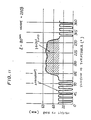
- Fig. 11 is a graphic diagram showing a revolved cross-section obtained by the ultrasonic sensor 6. As will be understood from Fig.
- the revolved cross-section includes a pulse-like varying portion which is caused by the leg portions 32 and net portions 33. Therefore, with the presence of the pulse-like varying portion being checked in the control section 5, it is possible to detect the category of cooking, i.e. thawing.
- Figs. 12 and 13 are cross-sectional views showing an automatic heating appliance according to another embodiment of the present invnetion, Fig. 12 being views from a side and Fig. 13 being viewed from the top.
- the ultrasonic sensor 6 is provided on a side wall of the heating chamber 7 so that the distance d from the side wall to the object 9 is detected.
- the reference 0 represents the origin, i.e. the center of rotation of the turntable 8.
- the turning radius r is varied in accordance with rotation of the turntable 8, and the plan project area of the object 9 can be obtained by the integral operation of the distance r , resulting in obtaining the external form of the object 9.
- the shape data can be obtained from the projected plan.
- the automation of the heating is more improved and, as shown in Fig. 2, the number of the keys are reduced to one or two, resulting in simple operation of the heating appliance.
- a heating appliance comprising a heating chamber, a heater for heating an object which is encased in the heating chamber and a turntable provided in the heating chamger and arranged to be rotatable about its own axis and to hold thereon the object.
- an ultrasonic sensor for transmitting an ultrasonic wave toward said object and receiving an echo wave returning therefrom and a control unit for controlling the ultrasonic sensor.
- the control unit successively calculates the distances of the object from said ultrasonic sensor on the basis of the transmission and reception of the ultrasonic wave and determines the heating condition of the object on the basis of the successively calculated distances and controlling the heater in accordance with the determined distinctive feature. This does not require an input operation in terms of the class and category of the object to be heated, resulting in improving the automation of the heating appliance.
Landscapes
- Physics & Mathematics (AREA)
- Electromagnetism (AREA)
- Electric Ovens (AREA)
Applications Claiming Priority (4)
| Application Number | Priority Date | Filing Date | Title |
|---|---|---|---|
| JP251111/86 | 1986-10-22 | ||
| JP61251111A JPH0675429B2 (ja) | 1986-10-22 | 1986-10-22 | 加熱装置 |
| JP1550687A JPH0670490B2 (ja) | 1987-01-26 | 1987-01-26 | 高周波加熱装置 |
| JP15506/87 | 1987-01-26 |
Publications (3)
| Publication Number | Publication Date |
|---|---|
| EP0264935A2 true EP0264935A2 (de) | 1988-04-27 |
| EP0264935A3 EP0264935A3 (en) | 1989-03-08 |
| EP0264935B1 EP0264935B1 (de) | 1992-04-22 |
Family
ID=26351679
Family Applications (1)
| Application Number | Title | Priority Date | Filing Date |
|---|---|---|---|
| EP87115454A Expired EP0264935B1 (de) | 1986-10-22 | 1987-10-21 | Automatisches Heizgerät mit Ultraschalldetektor |
Country Status (6)
| Country | Link |
|---|---|
| US (1) | US4831239A (de) |
| EP (1) | EP0264935B1 (de) |
| KR (1) | KR900008543B1 (de) |
| AU (1) | AU591353B2 (de) |
| CA (1) | CA1283461C (de) |
| DE (1) | DE3778480D1 (de) |
Cited By (16)
| Publication number | Priority date | Publication date | Assignee | Title |
|---|---|---|---|---|
| EP0275097A3 (en) * | 1987-01-16 | 1989-06-07 | Matsushita Electric Industrial Co., Ltd. | Heat cooking apparatus |
| EP0271899A3 (en) * | 1986-12-17 | 1989-10-18 | Matsushita Electric Industrial Co., Ltd. | Automatic heating appliance with identifying function of an object to be heated |
| EP0360341A3 (de) * | 1988-09-23 | 1991-08-28 | Ire Industrie Riunite Eurodomestici S.R.L. | Verfahren und Gerät zum Behandeln von eingefrorenen Lebensmitteln in einem Mikrowellenofen |
| EP0498669A1 (de) * | 1991-02-08 | 1992-08-12 | Kabushiki Kaisha Toshiba | Heizgerät |
| FR2692025A1 (fr) * | 1992-06-05 | 1993-12-10 | Toshiba Kk | Appareil de cuisson et procédé à détecteur pour sa mise en Óoeuvre. |
| EP0622973A1 (de) * | 1993-04-26 | 1994-11-02 | Kabushiki Kaisha Toshiba | Heizgerät mit einem Ultraschallwandler zur Konfigurationserfassung von Lebensmitteln |
| RU2122299C1 (ru) * | 1996-02-23 | 1998-11-20 | Самсунг Электроникс Ко., Лтд. | Устройство для управления работой нагревателя для микроволновой печи |
| RU2126608C1 (ru) * | 1996-02-23 | 1999-02-20 | Самсунг Электроникс Ко., Лтд. | Способ управления микроволновой печью (варианты) |
| RU2134495C1 (ru) * | 1996-02-23 | 1999-08-10 | Самсунг Электроникс Ко., Лтд | Микроволновая печь (варианты) |
| WO2007054917A3 (en) * | 2005-11-14 | 2007-09-07 | Arcelik As | An oven |
| EP1850642A1 (de) * | 2006-04-27 | 2007-10-31 | Brandt Industries | Verfahren zum Aufwärmen eines Nahrungsmittels und insbesondere eines Getränks in einem Mikrowellenherd |
| EP1921384A1 (de) | 2006-11-02 | 2008-05-14 | Electrolux Home Products Corporation N.V. | Vorrichtung und Verfahren zum Bestimmen der Temperatur im Inneren eines Garguts |
| EP2149755A1 (de) | 2008-07-30 | 2010-02-03 | Electrolux Home Products Corporation N.V. | Ofen und Betriebsverfahren dafür |
| CN102278779A (zh) * | 2010-06-09 | 2011-12-14 | 乐金电子(天津)电器有限公司 | 用于烧烤型微波炉的控制方法 |
| WO2013001475A1 (en) * | 2011-06-30 | 2013-01-03 | Thirodes Grandes Cuisines Poligny | Method of operating an oven through the image of its load |
| EP2930432A1 (de) * | 2014-04-07 | 2015-10-14 | Indesit Company S.p.A. | Garofen mit gewichtssensoren |
Families Citing this family (65)
| Publication number | Priority date | Publication date | Assignee | Title |
|---|---|---|---|---|
| US5171974A (en) * | 1987-10-29 | 1992-12-15 | Technology Licensing Corporation | Heating system for oven zone location |
| KR930001675B1 (ko) * | 1989-04-14 | 1993-03-08 | 가부시끼가이샤 히다찌세이사꾸쇼 | 비디오카메라의 화이트밸런스 조정장치 |
| US5111028A (en) * | 1989-09-11 | 1992-05-05 | White Consolidated Industries, Inc. | Method and control arrangement for cooking appliances |
| US4996403A (en) * | 1990-02-05 | 1991-02-26 | The United States Of America As Represented By The United States Department Of Energy | Acoustic emission feedback control for control of boiling in a microwave oven |
| US5099096A (en) * | 1990-04-05 | 1992-03-24 | Martin Marietta Energy Systems, Inc. | Microwave furnace having microwave compatible dilatometer |
| EP0455169B1 (de) * | 1990-04-28 | 1996-06-19 | Kabushiki Kaisha Toshiba | Kochstelle |
| JP2797657B2 (ja) * | 1990-06-01 | 1998-09-17 | 松下電器産業株式会社 | 高周波加熱装置 |
| KR930011809B1 (ko) * | 1990-12-18 | 1993-12-21 | 주식회사 금성사 | 전자레인지의 자동요리방법 및 그 장치 |
| KR940004051B1 (ko) * | 1991-10-12 | 1994-05-11 | 주식회사 금성사 | 소닉 디바이스 센서를 이용한 가열방법 |
| US5689060A (en) * | 1992-03-06 | 1997-11-18 | Matsushita Electric Industrial Co., Ltd. | Humidity measuring device and a heat cooker employing the device |
| US5302792A (en) * | 1992-05-18 | 1994-04-12 | Samsung Electronics Co., Ltd. | High frequency cooking device with turntable and weight sensor |
| DE4305498A1 (de) * | 1993-02-23 | 1994-08-25 | Loi Ind Ofenanlagen | Durchlaufofen mit Positionssensor |
| US5459303A (en) * | 1994-03-02 | 1995-10-17 | Goldstar Co., Ltd. | Method of preventing no-load operation of microwave oven |
| US5486685A (en) * | 1994-11-23 | 1996-01-23 | Dodds; W. Jean | Oven with food presence indicator |
| US6299920B1 (en) * | 1998-11-05 | 2001-10-09 | Premark Feg L.L.C. | Systems and method for non-invasive assessment of cooked status of food during cooking |
| SE514526C2 (sv) * | 1999-06-24 | 2001-03-05 | Whirlpool Co | Förfarande för styrning av ett kokningsförlopp i en mikrovågsugn samt mikrovågsugn härför |
| US6788211B2 (en) * | 2000-06-14 | 2004-09-07 | Edwards Systems Technology, Inc. | Apparatus and method using smoke and/or gas sensing in cooking devices |
| GB0202152D0 (en) * | 2002-01-30 | 2002-03-20 | Valor Ltd | Smoke effect apparatus |
| US7191698B2 (en) * | 2003-04-03 | 2007-03-20 | Battelle Memorial Institute | System and technique for ultrasonic determination of degree of cooking |
| US6867402B1 (en) | 2004-04-08 | 2005-03-15 | Maytag Corporation | System for sensing the presence of a load in an oven cavity of a microwave cooking appliance |
| JP2008271944A (ja) * | 2007-05-05 | 2008-11-13 | Shinyo Sangyo Kk | 水中超音波解凍機 |
| US8927913B2 (en) * | 2008-06-30 | 2015-01-06 | The Invention Science Fund I, Llc | Microwave processing systems and methods |
| US8610038B2 (en) * | 2008-06-30 | 2013-12-17 | The Invention Science Fund I, Llc | Microwave oven |
| US20090321428A1 (en) * | 2008-06-30 | 2009-12-31 | Hyde Roderick A | Microwave oven |
| RU2012104702A (ru) * | 2009-07-10 | 2013-08-20 | Панасоник Корпорэйшн | Устройство для микроволнового нагрева и способ управления микроволновым нагревом |
| JP5419573B2 (ja) * | 2009-07-22 | 2014-02-19 | 大和製罐株式会社 | 缶詰加熱装置 |
| EP3339744A1 (de) * | 2010-12-23 | 2018-06-27 | Miele & Cie. KG | Verfahren zum betreiben eines gargerätes und gargerät |
| EP2618634A1 (de) * | 2012-01-23 | 2013-07-24 | Whirlpool Corporation | Mikrowellenwärmungsvorrichtung |
| US20130269537A1 (en) * | 2012-04-16 | 2013-10-17 | Eugenio Minvielle | Conditioning system for nutritional substances |
| US20130269538A1 (en) | 2012-04-16 | 2013-10-17 | Eugenio Minvielle | Transformation system for nutritional substances |
| US9429920B2 (en) | 2012-04-16 | 2016-08-30 | Eugenio Minvielle | Instructions for conditioning nutritional substances |
| US20140069838A1 (en) | 2012-04-16 | 2014-03-13 | Eugenio Minvielle | Nutritional Substance Label System For Adaptive Conditioning |
| US9460633B2 (en) | 2012-04-16 | 2016-10-04 | Eugenio Minvielle | Conditioner with sensors for nutritional substances |
| US9702858B1 (en) | 2012-04-16 | 2017-07-11 | Iceberg Luxembourg S.A.R.L. | Dynamic recipe control |
| US9538880B2 (en) * | 2012-05-09 | 2017-01-10 | Convotherm Elektrogeraete Gmbh | Optical quality control system |
| JP5994107B2 (ja) * | 2012-10-02 | 2016-09-21 | パナソニックIpマネジメント株式会社 | 高周波加熱調理器 |
| US20150226438A1 (en) * | 2012-10-03 | 2015-08-13 | Bekir Ozyurt | Oven with increased cooking effectiveness |
| US9420641B2 (en) | 2013-01-23 | 2016-08-16 | Whirlpool Corporation | Microwave oven multiview silhouette volume calculation for mass estimation |
| EP2820985B1 (de) * | 2013-07-01 | 2018-10-17 | Electrolux Appliances Aktiebolag | Griller |
| US9668602B2 (en) * | 2013-09-09 | 2017-06-06 | Whirlpool Corporation | Cooking appliance |
| DE102013114227A1 (de) * | 2013-12-17 | 2015-06-18 | Rational Aktiengesellschaft | Gargerät mit Beschickungserkennung |
| US9933166B2 (en) | 2014-04-07 | 2018-04-03 | Whirlpool Emea S.P.A. | Oven comprising a scanning system |
| USD827356S1 (en) | 2016-02-11 | 2018-09-04 | Whirlpool Corporation | Oven |
| USD819386S1 (en) | 2016-02-11 | 2018-06-05 | Whirlpool Corporation | Oven |
| WO2018056977A1 (en) | 2016-09-22 | 2018-03-29 | Whirlpool Corporation | Method and system for radio frequency electromagnetic energy delivery |
| WO2018075025A1 (en) | 2016-10-19 | 2018-04-26 | Whirlpool Corporation | Food load cooking time modulation |
| EP3529536B1 (de) | 2016-10-19 | 2021-07-14 | Whirlpool Corporation | System und verfahren zur lebensmittelzubereitung mit einem mehrschichtigen modell |
| WO2018075026A1 (en) | 2016-10-19 | 2018-04-26 | Whirlpool Corporation | Method and device for electromagnetic cooking using closed loop control |
| US11197355B2 (en) | 2016-12-22 | 2021-12-07 | Whirlpool Corporation | Method and device for electromagnetic cooking using non-centered loads |
| EP3560291A4 (de) | 2016-12-22 | 2020-11-25 | Whirlpool Corporation | Verfahren und vorrichtung zum elektromagnetischen kochen unter verwendung von nicht-zentriertem lastmanagement durch spektromodale achsenrotation |
| US11343883B2 (en) | 2016-12-29 | 2022-05-24 | Whirlpool Corporation | Detecting changes in food load characteristics using Q-factor |
| US11917743B2 (en) | 2016-12-29 | 2024-02-27 | Whirlpool Corporation | Electromagnetic cooking device with automatic melt operation and method of controlling cooking in the electromagnetic cooking device |
| US11483906B2 (en) | 2016-12-29 | 2022-10-25 | Whirlpool Corporation | System and method for detecting cooking level of food load |
| JP6853876B2 (ja) | 2016-12-29 | 2021-03-31 | パナソニック株式会社 | 電磁調理装置及び電磁調理装置における調理を制御する方法 |
| EP3563635B1 (de) | 2016-12-29 | 2022-09-28 | Whirlpool Corporation | Elektromagnetische kochvorrichtung mit automatischer flüssigkeitserhitzung und verfahren zur kochsteuerung bei der elektromagnetischen kochvorrichtung |
| WO2018125151A1 (en) | 2016-12-29 | 2018-07-05 | Whirlpool Corporation | Electromagnetic cooking device with automatic anti-splatter operation and method of controlling cooking in the electromagnetic device |
| US11184960B2 (en) | 2016-12-29 | 2021-11-23 | Whirlpool Corporation | System and method for controlling power for a cooking device |
| EP3563634B1 (de) | 2016-12-29 | 2021-10-13 | Whirlpool Corporation | Elektromagnetische kochvorrichtung mit automatischer siedeerkennung und verfahren zur steuerung des kochvorgangs in der elektromagnetischen kochvorrichtung |
| EP3563629B1 (de) | 2016-12-29 | 2022-11-30 | Whirlpool Corporation | System und verfahren zur analyse des frequenzgangs einer elektromagnetischen kochvorrichtung |
| WO2018125136A1 (en) | 2016-12-29 | 2018-07-05 | Whirlpool Corporation | System and method for controlling a heating distribution in an electromagnetic cooking device |
| WO2018125129A1 (en) | 2016-12-29 | 2018-07-05 | Whirlpool Corporation | Electromagnetic cooking device with automatic popcorn popping feature and method of controlling cooking in the electromagnetic device |
| USD909811S1 (en) | 2016-12-30 | 2021-02-09 | Whirlpool Corporation | Panel for an oven |
| CN109393005B (zh) * | 2018-11-29 | 2022-12-13 | 河南科技学院 | 一种微波解冻猪肉的装置及方法 |
| US20250063640A1 (en) * | 2021-10-28 | 2025-02-20 | Lg Electronics Inc. | Cooking apparatus |
| US20240224386A1 (en) * | 2023-01-04 | 2024-07-04 | Haier Us Appliance Solutions, Inc. | Cooking appliance and methods of notification |
Family Cites Families (12)
| Publication number | Priority date | Publication date | Assignee | Title |
|---|---|---|---|---|
| GB1169166A (en) * | 1966-01-03 | 1969-10-29 | Microtherm Ltd | Improvements in or relating to Heating Apparatus |
| JPS6054561B2 (ja) * | 1975-05-20 | 1985-11-30 | 松下電器産業株式会社 | 加熱調理器 |
| US4278866A (en) * | 1975-12-05 | 1981-07-14 | Teledyne Industries, Inc. | Automatic electron beam deflecting circuit |
| US4157464A (en) * | 1977-08-19 | 1979-06-05 | Raytheon Company | Microwave heating system |
| JPS5640029A (en) * | 1979-09-07 | 1981-04-16 | Matsushita Electric Ind Co Ltd | Method and apparatus for controlling food heating |
| US4434341A (en) * | 1980-02-20 | 1984-02-28 | Busby Dennis L | Selective, locally defined heating of a body |
| JPS5824431A (ja) * | 1981-08-06 | 1983-02-14 | Sumitomo Rubber Ind Ltd | エラストマ−物品の予熱方法 |
| JPS5843329A (ja) * | 1981-09-09 | 1983-03-14 | Matsushita Electric Ind Co Ltd | 電子レンジ用すのこ網 |
| GB2117925B (en) * | 1982-02-19 | 1986-02-05 | Hitachi Heating Appl | Heating apparatus of thawing sensor controlled type |
| JPS6071825A (ja) * | 1983-09-28 | 1985-04-23 | Sharp Corp | 高周波加熱装置のヒ−タ電動装置 |
| JPS60258895A (ja) * | 1984-06-04 | 1985-12-20 | 松下電器産業株式会社 | 高周波加熱装置 |
| US4591684A (en) * | 1985-04-16 | 1986-05-27 | Sharp Kabushiki Kaisha | Cooking completion detection in a cooking appliance |
-
1987
- 1987-10-21 EP EP87115454A patent/EP0264935B1/de not_active Expired
- 1987-10-21 DE DE8787115454T patent/DE3778480D1/de not_active Expired - Lifetime
- 1987-10-21 US US07/111,434 patent/US4831239A/en not_active Expired - Lifetime
- 1987-10-21 AU AU80021/87A patent/AU591353B2/en not_active Ceased
- 1987-10-21 CA CA000549866A patent/CA1283461C/en not_active Expired - Lifetime
- 1987-10-22 KR KR1019870011740D patent/KR900008543B1/ko not_active Expired
Cited By (32)
| Publication number | Priority date | Publication date | Assignee | Title |
|---|---|---|---|---|
| EP0271899A3 (en) * | 1986-12-17 | 1989-10-18 | Matsushita Electric Industrial Co., Ltd. | Automatic heating appliance with identifying function of an object to be heated |
| EP0275097A3 (en) * | 1987-01-16 | 1989-06-07 | Matsushita Electric Industrial Co., Ltd. | Heat cooking apparatus |
| US4895067A (en) * | 1987-01-16 | 1990-01-23 | Matsushita Electric Industrial Co., Ltd. | Heat cooking apparatus |
| EP0360341A3 (de) * | 1988-09-23 | 1991-08-28 | Ire Industrie Riunite Eurodomestici S.R.L. | Verfahren und Gerät zum Behandeln von eingefrorenen Lebensmitteln in einem Mikrowellenofen |
| EP0498669A1 (de) * | 1991-02-08 | 1992-08-12 | Kabushiki Kaisha Toshiba | Heizgerät |
| US5221817A (en) * | 1991-02-08 | 1993-06-22 | Kabushiki Kaisha Toshiba | Heating apparatus |
| FR2692025A1 (fr) * | 1992-06-05 | 1993-12-10 | Toshiba Kk | Appareil de cuisson et procédé à détecteur pour sa mise en Óoeuvre. |
| US5369252A (en) * | 1992-06-05 | 1994-11-29 | Kabushiki Kaisha Toshiba | Cooking appliance and method with a light sensor |
| EP0622973A1 (de) * | 1993-04-26 | 1994-11-02 | Kabushiki Kaisha Toshiba | Heizgerät mit einem Ultraschallwandler zur Konfigurationserfassung von Lebensmitteln |
| RU2122299C1 (ru) * | 1996-02-23 | 1998-11-20 | Самсунг Электроникс Ко., Лтд. | Устройство для управления работой нагревателя для микроволновой печи |
| RU2126608C1 (ru) * | 1996-02-23 | 1999-02-20 | Самсунг Электроникс Ко., Лтд. | Способ управления микроволновой печью (варианты) |
| RU2134495C1 (ru) * | 1996-02-23 | 1999-08-10 | Самсунг Электроникс Ко., Лтд | Микроволновая печь (варианты) |
| WO2007054917A3 (en) * | 2005-11-14 | 2007-09-07 | Arcelik As | An oven |
| EP1850642A1 (de) * | 2006-04-27 | 2007-10-31 | Brandt Industries | Verfahren zum Aufwärmen eines Nahrungsmittels und insbesondere eines Getränks in einem Mikrowellenherd |
| FR2900533A1 (fr) * | 2006-04-27 | 2007-11-02 | Brandt Ind Sas | Procede de rechauffage d'un aliment, et notamment d'une boisson dans un four a micro-ondes |
| WO2008052747A3 (en) * | 2006-11-02 | 2008-07-31 | Electrolux Home Prod Corp | Device and method for determining the temperature inside an item to be cooked |
| EP1921384A1 (de) | 2006-11-02 | 2008-05-14 | Electrolux Home Products Corporation N.V. | Vorrichtung und Verfahren zum Bestimmen der Temperatur im Inneren eines Garguts |
| US8360633B2 (en) | 2006-11-02 | 2013-01-29 | Electrolux Home Products Corporation N.V. | Device and method for determining the temperature inside an item to be cooked |
| KR101419960B1 (ko) | 2006-11-02 | 2014-07-16 | 일렉트로룩스 홈 프로덕츠 코오포레이션 엔.브이. | 조리 대상물의 내부 온도를 판정하기 위한 장치 및 방법 |
| EP2149755A1 (de) | 2008-07-30 | 2010-02-03 | Electrolux Home Products Corporation N.V. | Ofen und Betriebsverfahren dafür |
| WO2010012340A1 (en) * | 2008-07-30 | 2010-02-04 | Electrolux Home Products Corporation N.V. | Oven and method of operating the same |
| US9494322B2 (en) | 2008-07-30 | 2016-11-15 | Electrolux Home Products Corporation N.V. | Oven and method of operating the same |
| CN102066843B (zh) * | 2008-07-30 | 2013-07-10 | 伊莱克斯家用产品股份有限公司 | 炉子及其操作方法 |
| US8563059B2 (en) | 2008-07-30 | 2013-10-22 | Electrolux Home Products Corporation N.V. | Oven and method of operating the same |
| AU2009275539B2 (en) * | 2008-07-30 | 2015-06-04 | Electrolux Home Products Corporation N.V. | Oven and method of operating the same |
| CN102278779B (zh) * | 2010-06-09 | 2015-06-17 | 乐金电子(天津)电器有限公司 | 用于烧烤型微波炉的控制方法 |
| CN102278779A (zh) * | 2010-06-09 | 2011-12-14 | 乐金电子(天津)电器有限公司 | 用于烧烤型微波炉的控制方法 |
| WO2013001475A1 (en) * | 2011-06-30 | 2013-01-03 | Thirodes Grandes Cuisines Poligny | Method of operating an oven through the image of its load |
| FR2977127A1 (fr) * | 2011-06-30 | 2013-01-04 | Thirode Grandes Cuisines Poligny | Procede de conduite d'un four par l'image de sa charge |
| EP2930432A1 (de) * | 2014-04-07 | 2015-10-14 | Indesit Company S.p.A. | Garofen mit gewichtssensoren |
| US9888804B2 (en) | 2014-04-07 | 2018-02-13 | Whirlpool Emea S.P.A. | Oven comprising weight sensors |
| EP2930432B1 (de) * | 2014-04-07 | 2018-09-19 | Whirlpool EMEA S.p.A | Garofen mit gewichtssensoren |
Also Published As
| Publication number | Publication date |
|---|---|
| EP0264935B1 (de) | 1992-04-22 |
| EP0264935A3 (en) | 1989-03-08 |
| US4831239A (en) | 1989-05-16 |
| KR900008543B1 (ko) | 1990-11-24 |
| DE3778480D1 (de) | 1992-05-27 |
| CA1283461C (en) | 1991-04-23 |
| AU591353B2 (en) | 1989-11-30 |
| AU8002187A (en) | 1988-06-02 |
Similar Documents
| Publication | Publication Date | Title |
|---|---|---|
| EP0264935B1 (de) | Automatisches Heizgerät mit Ultraschalldetektor | |
| EP0526297B1 (de) | Automatisches Kochgerät und Verfahren für einen Mikrowellenofen | |
| EP0271899B1 (de) | Automatisches Wärmegerät, versehen mit der Fähigkeit zur Identifizierung eines zu erwärmenden Gutes | |
| US6875969B2 (en) | Microwave oven and method of controlling the same | |
| US5828042A (en) | Uniform heating apparatus for microwave oven and method thereof | |
| US4591684A (en) | Cooking completion detection in a cooking appliance | |
| CA2295391C (en) | Automatic cooking control method for a microwave oven | |
| WO2005033584A1 (ja) | 電子レンジ | |
| US6806449B2 (en) | Apparatus and method of controlling a microwave oven | |
| EP0763963A2 (de) | Verfahren zum Steuern des Kochvorganges in einem Mikrowellenofen mittels einem Dampfdetektor | |
| JPS63105492A (ja) | 加熱装置 | |
| KR950010371B1 (ko) | 전자레인지 데우기/해동 제어방법 | |
| KR930006905B1 (ko) | 전자레인지에서의 음식 인식장치 | |
| KR950001229B1 (ko) | 전자레인지의 음식인식 요리장치 및 자동요리방법 | |
| KR100215031B1 (ko) | 전자렌지의 음식물온도판별장치 | |
| CN114729753B (zh) | 家用电器系统 | |
| JP2999661B2 (ja) | 加熱調理器 | |
| CN114729752B (zh) | 家用电器系统 | |
| KR0133437B1 (ko) | 전자레인지의 용기뚜껑 유무에 따른 추가가열시간 설정방법 | |
| KR950010373B1 (ko) | 전자레인지의 자동조리 방법 및 장치 | |
| JP2532396B2 (ja) | 加熱装置 | |
| JPH05172336A (ja) | 加熱調理器の被調理物判別装置 | |
| JPH05326133A (ja) | 高周波加熱装置 | |
| JPH07158859A (ja) | 加熱調理装置 | |
| JPH0674458A (ja) | 高周波加熱調理装置 |
Legal Events
| Date | Code | Title | Description |
|---|---|---|---|
| PUAI | Public reference made under article 153(3) epc to a published international application that has entered the european phase |
Free format text: ORIGINAL CODE: 0009012 |
|
| 17P | Request for examination filed |
Effective date: 19871021 |
|
| AK | Designated contracting states |
Kind code of ref document: A2 Designated state(s): DE FR GB IT SE |
|
| PUAL | Search report despatched |
Free format text: ORIGINAL CODE: 0009013 |
|
| AK | Designated contracting states |
Kind code of ref document: A3 Designated state(s): DE FR GB IT SE |
|
| 17Q | First examination report despatched |
Effective date: 19910729 |
|
| GRAA | (expected) grant |
Free format text: ORIGINAL CODE: 0009210 |
|
| AK | Designated contracting states |
Kind code of ref document: B1 Designated state(s): DE FR GB IT SE |
|
| ET | Fr: translation filed | ||
| REF | Corresponds to: |
Ref document number: 3778480 Country of ref document: DE Date of ref document: 19920527 |
|
| ITF | It: translation for a ep patent filed | ||
| PLBE | No opposition filed within time limit |
Free format text: ORIGINAL CODE: 0009261 |
|
| STAA | Information on the status of an ep patent application or granted ep patent |
Free format text: STATUS: NO OPPOSITION FILED WITHIN TIME LIMIT |
|
| 26N | No opposition filed | ||
| EAL | Se: european patent in force in sweden |
Ref document number: 87115454.8 |
|
| ITPR | It: changes in ownership of a european patent |
Owner name: OFFERTA DI LICENZA AL PUBBLICO |
|
| REG | Reference to a national code |
Ref country code: GB Ref legal event code: 746 Effective date: 19950928 |
|
| REG | Reference to a national code |
Ref country code: FR Ref legal event code: D6 |
|
| REG | Reference to a national code |
Ref country code: GB Ref legal event code: IF02 |
|
| PGFP | Annual fee paid to national office [announced via postgrant information from national office to epo] |
Ref country code: SE Payment date: 20051005 Year of fee payment: 19 |
|
| PGFP | Annual fee paid to national office [announced via postgrant information from national office to epo] |
Ref country code: FR Payment date: 20051010 Year of fee payment: 19 |
|
| PGFP | Annual fee paid to national office [announced via postgrant information from national office to epo] |
Ref country code: DE Payment date: 20051014 Year of fee payment: 19 |
|
| PGFP | Annual fee paid to national office [announced via postgrant information from national office to epo] |
Ref country code: GB Payment date: 20051019 Year of fee payment: 19 |
|
| PG25 | Lapsed in a contracting state [announced via postgrant information from national office to epo] |
Ref country code: IT Free format text: LAPSE BECAUSE OF NON-PAYMENT OF DUE FEES Effective date: 20051021 |
|
| PG25 | Lapsed in a contracting state [announced via postgrant information from national office to epo] |
Ref country code: SE Free format text: LAPSE BECAUSE OF NON-PAYMENT OF DUE FEES Effective date: 20061022 |
|
| PG25 | Lapsed in a contracting state [announced via postgrant information from national office to epo] |
Ref country code: DE Free format text: LAPSE BECAUSE OF NON-PAYMENT OF DUE FEES Effective date: 20070501 |
|
| EUG | Se: european patent has lapsed | ||
| GBPC | Gb: european patent ceased through non-payment of renewal fee |
Effective date: 20061021 |
|
| REG | Reference to a national code |
Ref country code: FR Ref legal event code: ST Effective date: 20070629 |
|
| PG25 | Lapsed in a contracting state [announced via postgrant information from national office to epo] |
Ref country code: GB Free format text: LAPSE BECAUSE OF NON-PAYMENT OF DUE FEES Effective date: 20061021 |
|
| PG25 | Lapsed in a contracting state [announced via postgrant information from national office to epo] |
Ref country code: FR Free format text: LAPSE BECAUSE OF NON-PAYMENT OF DUE FEES Effective date: 20061031 |