EP0265016A2 - Verfahren zur Herstellung eines Permanentmagneten - Google Patents
Verfahren zur Herstellung eines Permanentmagneten Download PDFInfo
- Publication number
- EP0265016A2 EP0265016A2 EP87201999A EP87201999A EP0265016A2 EP 0265016 A2 EP0265016 A2 EP 0265016A2 EP 87201999 A EP87201999 A EP 87201999A EP 87201999 A EP87201999 A EP 87201999A EP 0265016 A2 EP0265016 A2 EP 0265016A2
- Authority
- EP
- European Patent Office
- Prior art keywords
- permanent magnet
- magnet
- magnetic
- field
- high energy
- Prior art date
- Legal status (The legal status is an assumption and is not a legal conclusion. Google has not performed a legal analysis and makes no representation as to the accuracy of the status listed.)
- Ceased
Links
- 238000000034 method Methods 0.000 title claims description 23
- 230000008569 process Effects 0.000 title description 4
- 230000005291 magnetic effect Effects 0.000 claims abstract description 68
- 238000003825 pressing Methods 0.000 claims abstract description 66
- 229910001172 neodymium magnet Inorganic materials 0.000 claims abstract description 37
- 229910045601 alloy Inorganic materials 0.000 claims abstract description 33
- 239000000956 alloy Substances 0.000 claims abstract description 33
- 239000000843 powder Substances 0.000 claims abstract description 31
- 229910052761 rare earth metal Inorganic materials 0.000 claims abstract description 17
- 229910052723 transition metal Inorganic materials 0.000 claims abstract description 13
- -1 rare earth transition metal Chemical class 0.000 claims abstract description 10
- ZOXJGFHDIHLPTG-UHFFFAOYSA-N Boron Chemical compound [B] ZOXJGFHDIHLPTG-UHFFFAOYSA-N 0.000 claims abstract description 9
- 229910052796 boron Inorganic materials 0.000 claims abstract description 9
- 238000005245 sintering Methods 0.000 claims abstract description 9
- 238000004519 manufacturing process Methods 0.000 claims description 13
- 239000000696 magnetic material Substances 0.000 claims description 8
- 150000002910 rare earth metals Chemical class 0.000 claims description 8
- 229910000765 intermetallic Inorganic materials 0.000 claims description 7
- 239000002245 particle Substances 0.000 claims description 7
- 230000004907 flux Effects 0.000 claims description 5
- 239000000470 constituent Substances 0.000 claims description 4
- 150000003624 transition metals Chemical class 0.000 claims description 4
- 238000003754 machining Methods 0.000 claims description 3
- 238000010583 slow cooling Methods 0.000 claims description 3
- 230000006835 compression Effects 0.000 claims description 2
- 238000007906 compression Methods 0.000 claims description 2
- 229910000583 Nd alloy Inorganic materials 0.000 abstract 1
- PXAWCNYZAWMWIC-UHFFFAOYSA-N [Fe].[Nd] Chemical compound [Fe].[Nd] PXAWCNYZAWMWIC-UHFFFAOYSA-N 0.000 abstract 1
- XEEYBQQBJWHFJM-UHFFFAOYSA-N Iron Chemical compound [Fe] XEEYBQQBJWHFJM-UHFFFAOYSA-N 0.000 description 18
- 229910000938 samarium–cobalt magnet Inorganic materials 0.000 description 10
- 230000005294 ferromagnetic effect Effects 0.000 description 9
- 229910052742 iron Inorganic materials 0.000 description 9
- KPLQYGBQNPPQGA-UHFFFAOYSA-N cobalt samarium Chemical compound [Co].[Sm] KPLQYGBQNPPQGA-UHFFFAOYSA-N 0.000 description 7
- UONOETXJSWQNOL-UHFFFAOYSA-N tungsten carbide Chemical compound [W+]#[C-] UONOETXJSWQNOL-UHFFFAOYSA-N 0.000 description 6
- 229910001209 Low-carbon steel Inorganic materials 0.000 description 5
- 239000010935 stainless steel Substances 0.000 description 5
- 229910001220 stainless steel Inorganic materials 0.000 description 5
- 229910001369 Brass Inorganic materials 0.000 description 4
- 229910001347 Stellite Inorganic materials 0.000 description 4
- 239000010951 brass Substances 0.000 description 4
- AHICWQREWHDHHF-UHFFFAOYSA-N chromium;cobalt;iron;manganese;methane;molybdenum;nickel;silicon;tungsten Chemical compound C.[Si].[Cr].[Mn].[Fe].[Co].[Ni].[Mo].[W] AHICWQREWHDHHF-UHFFFAOYSA-N 0.000 description 4
- RTAQQCXQSZGOHL-UHFFFAOYSA-N Titanium Chemical compound [Ti] RTAQQCXQSZGOHL-UHFFFAOYSA-N 0.000 description 3
- 239000000463 material Substances 0.000 description 3
- 239000010936 titanium Substances 0.000 description 3
- 229910052719 titanium Inorganic materials 0.000 description 3
- 229910052779 Neodymium Inorganic materials 0.000 description 2
- 229910052772 Samarium Inorganic materials 0.000 description 2
- 230000008901 benefit Effects 0.000 description 2
- NDYCBWZIOSTTHS-UHFFFAOYSA-N cobalt samarium Chemical compound [Co].[Co].[Co].[Co].[Co].[Sm] NDYCBWZIOSTTHS-UHFFFAOYSA-N 0.000 description 2
- 239000000203 mixture Substances 0.000 description 2
- 230000004048 modification Effects 0.000 description 2
- 238000012986 modification Methods 0.000 description 2
- QEFYFXOXNSNQGX-UHFFFAOYSA-N neodymium atom Chemical compound [Nd] QEFYFXOXNSNQGX-UHFFFAOYSA-N 0.000 description 2
- KZUNJOHGWZRPMI-UHFFFAOYSA-N samarium atom Chemical compound [Sm] KZUNJOHGWZRPMI-UHFFFAOYSA-N 0.000 description 2
- VYZAMTAEIAYCRO-UHFFFAOYSA-N Chromium Chemical compound [Cr] VYZAMTAEIAYCRO-UHFFFAOYSA-N 0.000 description 1
- 229910000531 Co alloy Inorganic materials 0.000 description 1
- 229910052777 Praseodymium Inorganic materials 0.000 description 1
- 230000004075 alteration Effects 0.000 description 1
- 230000000712 assembly Effects 0.000 description 1
- 238000000429 assembly Methods 0.000 description 1
- 230000004888 barrier function Effects 0.000 description 1
- 230000015572 biosynthetic process Effects 0.000 description 1
- 238000005266 casting Methods 0.000 description 1
- 239000010941 cobalt Substances 0.000 description 1
- 229910017052 cobalt Inorganic materials 0.000 description 1
- GUTLYIVDDKVIGB-UHFFFAOYSA-N cobalt atom Chemical compound [Co] GUTLYIVDDKVIGB-UHFFFAOYSA-N 0.000 description 1
- 238000005056 compaction Methods 0.000 description 1
- 238000010276 construction Methods 0.000 description 1
- 238000009826 distribution Methods 0.000 description 1
- 238000000227 grinding Methods 0.000 description 1
- 238000001746 injection moulding Methods 0.000 description 1
- 239000006249 magnetic particle Substances 0.000 description 1
- 239000006247 magnetic powder Substances 0.000 description 1
- 238000003801 milling Methods 0.000 description 1
- 238000000465 moulding Methods 0.000 description 1
- 230000005405 multipole Effects 0.000 description 1
- AJCDFVKYMIUXCR-UHFFFAOYSA-N oxobarium;oxo(oxoferriooxy)iron Chemical compound [Ba]=O.O=[Fe]O[Fe]=O.O=[Fe]O[Fe]=O.O=[Fe]O[Fe]=O.O=[Fe]O[Fe]=O.O=[Fe]O[Fe]=O.O=[Fe]O[Fe]=O AJCDFVKYMIUXCR-UHFFFAOYSA-N 0.000 description 1
- 230000002093 peripheral effect Effects 0.000 description 1
- PUDIUYLPXJFUGB-UHFFFAOYSA-N praseodymium atom Chemical compound [Pr] PUDIUYLPXJFUGB-UHFFFAOYSA-N 0.000 description 1
- 239000011347 resin Substances 0.000 description 1
- 229920005989 resin Polymers 0.000 description 1
- 230000001360 synchronised effect Effects 0.000 description 1
Images


Classifications
-
- H—ELECTRICITY
- H01—ELECTRIC ELEMENTS
- H01F—MAGNETS; INDUCTANCES; TRANSFORMERS; SELECTION OF MATERIALS FOR THEIR MAGNETIC PROPERTIES
- H01F41/00—Apparatus or processes specially adapted for manufacturing or assembling magnets, inductances or transformers; Apparatus or processes specially adapted for manufacturing materials characterised by their magnetic properties
- H01F41/02—Apparatus or processes specially adapted for manufacturing or assembling magnets, inductances or transformers; Apparatus or processes specially adapted for manufacturing materials characterised by their magnetic properties for manufacturing cores, coils, or magnets
- H01F41/0253—Apparatus or processes specially adapted for manufacturing or assembling magnets, inductances or transformers; Apparatus or processes specially adapted for manufacturing materials characterised by their magnetic properties for manufacturing cores, coils, or magnets for manufacturing permanent magnets
- H01F41/0273—Imparting anisotropy
-
- B—PERFORMING OPERATIONS; TRANSPORTING
- B22—CASTING; POWDER METALLURGY
- B22F—WORKING METALLIC POWDER; MANUFACTURE OF ARTICLES FROM METALLIC POWDER; MAKING METALLIC POWDER; APPARATUS OR DEVICES SPECIALLY ADAPTED FOR METALLIC POWDER
- B22F3/00—Manufacture of workpieces or articles from metallic powder characterised by the manner of compacting or sintering; Apparatus specially adapted therefor ; Presses and furnaces
- B22F3/02—Compacting only
-
- H—ELECTRICITY
- H01—ELECTRIC ELEMENTS
- H01F—MAGNETS; INDUCTANCES; TRANSFORMERS; SELECTION OF MATERIALS FOR THEIR MAGNETIC PROPERTIES
- H01F1/00—Magnets or magnetic bodies characterised by the magnetic materials therefor; Selection of materials for their magnetic properties
- H01F1/01—Magnets or magnetic bodies characterised by the magnetic materials therefor; Selection of materials for their magnetic properties of inorganic materials
- H01F1/03—Magnets or magnetic bodies characterised by the magnetic materials therefor; Selection of materials for their magnetic properties of inorganic materials characterised by their coercivity
- H01F1/032—Magnets or magnetic bodies characterised by the magnetic materials therefor; Selection of materials for their magnetic properties of inorganic materials characterised by their coercivity of hard-magnetic materials
- H01F1/04—Magnets or magnetic bodies characterised by the magnetic materials therefor; Selection of materials for their magnetic properties of inorganic materials characterised by their coercivity of hard-magnetic materials metals or alloys
- H01F1/047—Alloys characterised by their composition
- H01F1/053—Alloys characterised by their composition containing rare earth metals
- H01F1/055—Alloys characterised by their composition containing rare earth metals and magnetic transition metals, e.g. SmCo5
- H01F1/057—Alloys characterised by their composition containing rare earth metals and magnetic transition metals, e.g. SmCo5 and IIIa elements, e.g. Nd2Fe14B
- H01F1/0571—Alloys characterised by their composition containing rare earth metals and magnetic transition metals, e.g. SmCo5 and IIIa elements, e.g. Nd2Fe14B in the form of particles, e.g. rapid quenched powders or ribbon flakes
- H01F1/0575—Alloys characterised by their composition containing rare earth metals and magnetic transition metals, e.g. SmCo5 and IIIa elements, e.g. Nd2Fe14B in the form of particles, e.g. rapid quenched powders or ribbon flakes pressed, sintered or bonded together
- H01F1/0576—Alloys characterised by their composition containing rare earth metals and magnetic transition metals, e.g. SmCo5 and IIIa elements, e.g. Nd2Fe14B in the form of particles, e.g. rapid quenched powders or ribbon flakes pressed, sintered or bonded together pressed, e.g. hot working
-
- H—ELECTRICITY
- H02—GENERATION; CONVERSION OR DISTRIBUTION OF ELECTRIC POWER
- H02K—DYNAMO-ELECTRIC MACHINES
- H02K15/00—Processes or apparatus specially adapted for manufacturing, assembling, maintaining or repairing of dynamo-electric machines
- H02K15/02—Processes or apparatus specially adapted for manufacturing, assembling, maintaining or repairing of dynamo-electric machines of stator or rotor bodies
- H02K15/03—Processes or apparatus specially adapted for manufacturing, assembling, maintaining or repairing of dynamo-electric machines of stator or rotor bodies having permanent magnets
Definitions
- the invention relates to a method of manufacturing a magnet from a magnetic material the main phase of which comprises an intermetallic compound of the rare earth transition metal type which also includes boron, comprising the steps of:-
- the invention further relates to apparatus for manufacturing said magnets, and to magnets manufactured by the method and apparatus.
- Magnetic materials based on intermetallic compounds of certain rare earth metals with transition metals may be formed into permanent magnets having coercive fields of considerable magnitude, namely of several hundred kA/m.
- the constituent materials are alloyed in an inert atmosphere or in vacuo.
- the alloy is then comminuted into particles whose average size lies in the range 0.3 to 80um and is preferably less than about 10um, which are aligned in a magnetic field while being formed into a magnet body by compacting under a pressure of about 10kN/cm2.
- the alignment of the particles is fixed and the particles bonded together by sintering in an inert atmosphere or in vacuo at a temperature in the range of approximately 800 to 1200 degrees C.
- NdFeB samarium cobalt magnets
- NdFeB will be used herein generally to refer to commercially useful neodymium iron boron magnet alloys whether partially substituted or not.
- a magnet body from a powder mass is carried out in a suitably shaped pressing chamber of a press, which forms part of the magnetic circuit of associated electromagnets which are arranged to provide the necessary magnetic alignment field.
- This entails the provision of specially constructed presses and major alterations may have to be made to the presses when different forms of magnet body or of magnetic alignment patterns, are to be made.
- electromagnets to supply the necessary alignment field also means that it is impractical to form a magnet body with a complex multipolar alignment pattern in one piece and it has hitherto been necessary in such a case, to form the magnet body as a plurality of parts each with a simple alignment pattern and to assemble the parts at a later stage to form the desired magnet body.
- An example of such a magnet body would be a multipolar rotor for a stepping motor.
- a rotor can be formed as a cylinder using a uniform radial alignment field using an electromagnet arrangement.
- a rotor of this kind is subsequently magnetised with a distribution of alternate poles, it is found that the location of the poles tends to be insufficiently well defined.
- a method of manufacturing a magnet from a magnetic material the main phase of which comprises an intermetallic compound of the rare earth transition metal type which also includes boron comprising the steps of:-
- apparatus for carrying out the said method including a pressing tool having a pressing chamber in which the magnetic body is pressed and having magnetic circuit means for applying an aligning magnetic field to the alloy powder while it is being pressed, characterised in that the source of magnetomotive force employed in the magnetic circuit means to generate the aligning magnetic field comprises permanent magnet means including at least one high energy permanent magnet.
- the present invention is not concerned with magnetising the finished magnet but with an intermediate step during the manufacture of sintered NdFeB magnets in which the powdered alloy is subjected to an alignment field while a magnet body is being formed by pressing the loose powder in a pressing chamber.
- One example relating to pressing a magnet body in the manufacture of a samarium cobalt magnet requires respective aligning field intensities for a given SmCo5 powder, in excess of about 800kA/m and 1000kA/m in order to provide a finished magnet having respectively 90% and 95% of the maximum realisable remanence of about 0.89T.
- the invention is based on the realisation that in the case of certain rare earth transition metal type alloys, such as Nd2Fe14B, which are referred to herein as NdFeB alloys, as much as 95% of the maximum attainable remanence can be achieved by using a relatively low aligning field intensity of 400kA/m or less, and that such a field intensity can be readily attained by the use of commercially available high energy permanent magnets i.e.
- magnets having, for example, a maximum BH product on the demagnetisation curve, (BH) max , of not less than 32kJ/m3 and preferably not less than 80kJ/m3, and a flux density Bd corresponding to (BH) max of not less than 300mT, such as can be formed by some cobalt alloys or by suitable rare earth sintered magnets employing samarium cobalt or NdFeB alloys arranged in a reasonably efficient magnetic circuit of soft iron so as to include the pressing chamber which is to contain the NdFeB alloy powder from which the magnet body is to be pressed prior to being sintered.
- BH maximum BH product on the demagnetisation curve
- the aligning magnetic field intensity required to attain a given fraction of the maximum realisable remanence depends on the direction of the aligning field relative to the direction of the applied pressing force.
- respective alignment field strengths of 280kA/m and of 90kA/m enabled about 95% and 90% of the maximum remanence to be attained, while for a similar result to be achieved when a perpendicular relationship exists between the directions of the alignment field and the applied pressure, the respective alignment field strengths were 360kA/m and 180kA/m.
- the maximum attainable remanence for a typical SmCo5 magnet is about 0.89T while the corresponding maxima for the above mentioned example of NdFeB alloy was 1.09T and 1.18T for the parallel and perpendicular relative orientations of the alignment field and the pressing force respectively. From this it will be seen in the case of the NdFeB alloy that even the application of a smaller alignment field than is required to achieve 90% of the realisable remanence of e.g. 1.18T, can provide a sintered magnet having a remanence greater than 0.9T which is greater than the maximum realisable remanence when using a SmCo5 alloy and an alignment field of very high intensity.
- a method and apparatus in accordance with the invention provides the advantage that the aligning permanent magnets can be incorporated into a compact pressing chamber assembly which can be employed in a standard pressing machine thus avoiding the expense of constructing or adapting a press to accommodate suitable electromagnets.
- a particular advantage is that complex alignment patterns of preferred magnetisation may be introduced into magnet bodies in a single step process using a simple and compact aligning assembly without the need to manufacture the finished magnet body from a number of individually aligned segments. For example multipole rotor magnets for generators or for motors, notably for stepper motors, can be formed which show well defined pole positions after magnetisation.
- FIG. 1 One form of apparatus in accordance with the invention is illustrated by the detail of the pressing tool of an otherwise conventional press, shown in vertical and horizontal section in Figures 1 and 2 respectively and which depict the pressing chamber and associated magnetic circuit assembly employed in carrying out the method in accordance with the invention.
- the press itself can take any convenient form and can be a mechanical press or a hydraulic press.
- the high purity alloy powder of average particle size 5um resulting from milling and grinding in an inert atmosphere or in vacuo, a casting made of the NdFeB composition, for example Nd15Fe77B8, to be used as magnet material, is placed in the pressing chamber 1 of the die assembly 2 of the pressing tool, which is located on the stationary plattern 3 of the press (not shown).
- a diehead 4 carried on the outer end of an upper plunger 5 is then used to compress the powder in the chamber 1 to a pressure in the range 5 to 30kN/cm2 against a counterhead 14 also actuated by the press via a lower plunger (not shown).
- the pressing chamber is formed in a strong non-magnetic block 6 made of a form of tungsten carbide manufactured under the Trade Mark "STELLITE", and a magnetic circuit is set up about the chamber 1 via soft iron pieces 7, 8 and 9.
- Alternative non-magnetic materials which can be used to contain the powder are stainless steel, brass, or in the form of a thin sheet construction, titanium.
- the magnetomotive force required to provide the desired alignment field, in this case perpendicular to the pressing direction, in the alloy powder in the chamber 1 is supplied by high energy permanent magnets 10 and 11 formed in the present example of sintered NdFeB although other forms of high energy permanent magnets such as samarium colbalt magnets can be employed.
- a high energy permanent magnet 10, 11, for use in the described apparatus would preferably be characterised by a value of not less than 300mT for the fluxdensity Bd which corresponds to the maximum value of the BH product, (BH) max , on the demagnetisation curve and which value would be preferably not less than 32kJ/m3 and more satisfactorily not less than 80kJ/m3.
- Figure 3 is a graph indicating the relationships between the remanence Br after saturation of the sintered and annealed magnet bodies and the magnitude of the alignment field employed during the process of pressing the powder to form the magnet body before sintering.
- the curves 20 and 21 relate to magnet bodies formed of NdFeB and the curve 22 relates to a magnet body formed of SmCo5.
- the curve 20 relates to the situation illustrated in Figures 1 and 2 in which the alignment field is perpendicular to the pressing direction while the curve 21 relates to an alignment field directed parallel to the pressing direction.
- the curve 20 tends to an ultimate value of about 1.18T while the curve 21 tends to an ultimate value of about 1.09T for high values of the alignment field.
- an alignment field of about 360kA/m provides a remanence of about 1.12T
- the parallel orientation requires an alignment field of about 280kA/m providing a remanence of about 1.03T.
- Such values of alignment field can be readily attained in a sufficiently efficient magnetic circuit using sintered NdFeB magnets to supply the magnetomotive force, thus enabling a compact moulding chamber assembly to be constructed which can be used with a standard hydraulic or mechanical press.
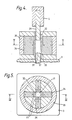
- FIGS 4 and 5 illustrate a further form of apparatus in accordance with the invention for manufacturing a rotor in the form of a four pole magnet.
- the pressing chamber 31 is formed within a non-magnetic cylindrical sleeve 32 suitably of stainless steel, surrounded by four mild steel pole pieces 33 each abutting one end of a corresponding NdFeB magnet bar 34 whose other end makes magnetic contact with a surrounding cylinder of mild steel 35 which completes the magnetic circuit.
- the magnets 34 are arranged alternately with opposite poles applied to the pole pieces 33.
- the remainder of the pressing chamber assembly is formed of non-magnetic material to contain the pressure exerted by the press.
- a non-magnetic die-head 36 carried on the outer end of the upper plunger 5 is employed to compress the powder against a counterhead 37 carried on a lower plunger (not shown), as in the case of Figures 1 and 2, although in this case both are of circular cross section.
- Figure 6 illustrates a further form of apparatus in accordance with the invention for manufacturing an annular Nd-Fe-B magnet in which a uniform radial alignment field is employed.
- a magnet can be subsequently magnetised with a large number of alternate peripheral poles to form the rotor of a synchronous clock motor.
- annular pressing chamber 41 is formed between the end faces of a cylindrical non-magnetic upper punch 42 and a cylindrical non-magnetic lower punch 43 and between the outer cylindrical non-magnetic insert 44 and an inner ferromagnetic core 45, suitable of soft iron, whose outer surface in the vicinity of the pressing chamber, can also be provided with a non-magnetic insert (not shown) if desired.
- a radial magnetic alignment field is generated in the pressing chamber 41 by a high-energy permanent magnet insert 46 formed either by an annular Nd-Fe-B magnet or an assembly of Nd-Fe-B magnets arranged side by side, and is applied to the pressing chamber 41 via a magnetic circuit formed by soft iron members 47, 48, 49, an inner pole formed by the ferromagnetic core 45 and an annular outer pole piece 50 also of soft iron.
- the pressing chamber and the associated magnetic circuit are contained and located within a non-magnetic casing formed by a cylindrical outer wall 51 and similar upper and lower end walls 52, 53, suitably formed of non-ferromagnetic stainless steel, tungsten carbide e.g. "STELLITE" or brass.
- the casing is placed on the stationary platten 3 of a double-acting press (not shown) and is located thereon by one or more locating pins 54.
- the lower punch (diehead) 43 is arranged to be freely moveable in a vertical direction along the inner core 45, and is mounted on an annular support 55 attached by three support columns 56 arranged to pass freely through corresponding apertures in the members 49 and 53, to a base 57 which rests on the lower plunger 60 of the press.
- the upper punch (diehead 42) is urged downwardly by the upper plunger 5 in order to compress powder present in the pressing chamber 41.
- the pressing chamber will be empty, the upper plunger 5 will be raised and the upper punch 42 will be removed.
- the lower punch 43 is positioned by means of the lower plunger so that the volume of the pressing chamber 41 below the top surface of the upper end wall 52 is that required to accommodate the correct charge of loose, comminuted Nd-Fe-B powder.
- Nd-Fe-B powder is loaded into the chamber 41 and the top levelled off to the upper surface of the end wall 52 with a straight edge.
- the end of the inner ferromagnetic core 45 is provided with a non-magnetic end cap 58 so that surplus magnetic particles can be freely removed.
- the upper punch 42 is then placed in position as the lower punch is retracted slightly by lowering the lower plunger 60 to the position shown in Figure 6.
- the upper plunger 5 is then caused to descend onto the anvil top of the upper punch 42 and the press force increased so that the powder in the chamber 41 is compressed to a pressure in the range 5 to 30 kN/cm2.
- the press force is released and the lower plunger 60 is raised so that the upper surface of the lower plunger 43 is flush with the upper surface of the end wall 52 and the of the end cap 58.
- the upper plunger 5 is further raised and the upper punch 42 is lifted off thus enabling the pressed and aligned annular magnet body to be removed for sintering and further processing.
- the upper punch 42 may be attached at its upper, anvil end to the end surface of the upper plunger 5 so that it is lifted automatically from the pressed magnet body without the need for manual intervention.
- the radial alignment field maintained in the pressing chamber by the Nd-Fe-B magnets 46 was in the range 280 kA/m to 320 kA/m.
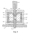
- Figure 7 illustrates diagrammatically a form of apparatus in accordance with the invention for pressing an Nd-Fe-B magnet body prior to sintering, in which an alignment magnetic field is provided which is parallel to the pressing direction.
- a pressing chamber 71 is formed between the end faces of an upper punch 72 and a lower punch 73 and within a non-magnetic cylindrical wall liner 74, suitably of tungsten carbide e.g "STELLITE".
- the upper and lower punches 72, 73 are ferromagnetic, suitably of mild steel with their end faces provided with non-ferromagnetic end caps 75, 76, suitably of tungsten carbide.
- a longitudinal magnetic alignment field is generated in the pressing chamber 71 by a high-energy permanent magnet insert 78 formed by an assembly of Nd-Fe-B magnets or by an annular Nd-Fe-B magnet, and is applied to the pressing chamber 71 via a magnetic circuit formed by ferromagnetic members 80, 81, suitably of soft iron or mild steel and the corresponding upper and lower punches 72, 73.
- the pressing chamber and the associated magnetic circuit are contained and located within a non-ferromagnetic casing formed by a cylindrical outer wall 83 and upper and lower end walls 84, 85, suitably formed from stainless steel, tungsten carbide e.g.
- STELLITE or brass
- the inner region 87 can be filled with a suitable non-ferromagnetic support medium, suitably brass, stainless steel, tungsten carbide or a suitable curable resin.
- the casing is placed on the stationary platten 3 of a double acting press (not shown), and the press is operated in a manner similar to the other embodiments herein described.
- the press of Figure 7 can be employed to form magnet bodies of any desired cross section for example circular or rectangular.
- the magnetic circuit elements 80 and 81 are tapered towards the pressing chamber 71 to render the longitudinal field more uniform.
- the upper central portion of the upper magnetic circuit element 80 is also tapered downwards in the vicinity of the central passage into the chamber 71 so that when the upper punch 72 is withdrawn, comminuted Nd-Fe-B powder can be readily loaded into the chamber 71 and the upper punch 72 re-introduced without the difficulty mentioned above of powder being attracted out of the chamber 71.
- the magnet body is removed as in the other embodiments, by raising the lower punch.
Landscapes
- Engineering & Computer Science (AREA)
- Power Engineering (AREA)
- Manufacturing & Machinery (AREA)
- Mechanical Engineering (AREA)
- Chemical & Material Sciences (AREA)
- Crystallography & Structural Chemistry (AREA)
- Inorganic Chemistry (AREA)
- Powder Metallurgy (AREA)
- Hard Magnetic Materials (AREA)
- Manufacturing Cores, Coils, And Magnets (AREA)
Applications Claiming Priority (2)
| Application Number | Priority Date | Filing Date | Title |
|---|---|---|---|
| GB8625099A GB2196479B (en) | 1986-10-20 | 1986-10-20 | Method and apparatus for the manufacture of rare earth transition metal alloy magnets |
| GB8625099 | 1986-10-20 |
Publications (2)
| Publication Number | Publication Date |
|---|---|
| EP0265016A2 true EP0265016A2 (de) | 1988-04-27 |
| EP0265016A3 EP0265016A3 (de) | 1990-05-02 |
Family
ID=10606027
Family Applications (1)
| Application Number | Title | Priority Date | Filing Date |
|---|---|---|---|
| EP87201999A Ceased EP0265016A3 (de) | 1986-10-20 | 1987-10-19 | Verfahren zur Herstellung eines Permanentmagneten |
Country Status (4)
| Country | Link |
|---|---|
| EP (1) | EP0265016A3 (de) |
| JP (1) | JPS63110605A (de) |
| AU (1) | AU7993887A (de) |
| GB (1) | GB2196479B (de) |
Cited By (4)
| Publication number | Priority date | Publication date | Assignee | Title |
|---|---|---|---|---|
| FR2652535A1 (fr) * | 1989-10-03 | 1991-04-05 | Caine Stephane | Procede de fabrication simplifiee de pastilles de composition donnee appartenant au groupe des supraconducteurs, des ferrites et des materiaux a structure granulaire complexe. |
| EP1659596A1 (de) * | 2004-11-18 | 2006-05-24 | Aichi Steel Corporation | Vorrichtung zur Herstellung eines Ringmagneten oder eines gekrümmten Magneten |
| US7367791B2 (en) | 2004-11-19 | 2008-05-06 | Aichi Steel Corporation | Device for producing annular or arcuate magnet |
| WO2014159828A1 (en) * | 2013-03-14 | 2014-10-02 | Agricultural Magnetics, Ltd. | Apparatus for reconfiguring spray equipment, and method |
Families Citing this family (3)
| Publication number | Priority date | Publication date | Assignee | Title |
|---|---|---|---|---|
| AU609669B2 (en) * | 1986-10-13 | 1991-05-02 | N.V. Philips Gloeilampenfabrieken | Method of manufacturing a permanent magnet |
| CN103042211B (zh) * | 2012-07-27 | 2015-02-11 | 王秋安 | 一种辐射取向烧结钕铁硼磁环的模具及其制作工艺 |
| CN105006326B (zh) * | 2015-07-27 | 2017-03-01 | 北京工业大学 | 一种NdFeB/SmCo5多层复合稀土永磁体及SPS热压法制备方法 |
Family Cites Families (7)
| Publication number | Priority date | Publication date | Assignee | Title |
|---|---|---|---|---|
| NL93759C (de) * | 1953-04-11 | |||
| GB838451A (en) * | 1956-03-23 | 1960-06-22 | Licentia Gmbh | A die for compressing finely divided magnetic materials within a magnetic field |
| GB1019493A (en) * | 1964-02-28 | 1966-02-09 | Alexander Waldemar Cochardt | Ring magnet |
| CA1316375C (en) * | 1982-08-21 | 1993-04-20 | Masato Sagawa | Magnetic materials and permanent magnets |
| US4444550A (en) * | 1982-10-20 | 1984-04-24 | Loubier Robert J | Permanent magnet mold apparatus for injection molding plastic bonded magnets |
| JPS59216453A (ja) * | 1983-05-20 | 1984-12-06 | Hitachi Metals Ltd | 円筒状永久磁石の製造方法 |
| US4601875A (en) * | 1983-05-25 | 1986-07-22 | Sumitomo Special Metals Co., Ltd. | Process for producing magnetic materials |
-
1986
- 1986-10-20 GB GB8625099A patent/GB2196479B/en not_active Expired - Lifetime
-
1987
- 1987-10-19 EP EP87201999A patent/EP0265016A3/de not_active Ceased
- 1987-10-20 AU AU79938/87A patent/AU7993887A/en not_active Abandoned
- 1987-10-20 JP JP62262920A patent/JPS63110605A/ja active Pending
Cited By (6)
| Publication number | Priority date | Publication date | Assignee | Title |
|---|---|---|---|---|
| FR2652535A1 (fr) * | 1989-10-03 | 1991-04-05 | Caine Stephane | Procede de fabrication simplifiee de pastilles de composition donnee appartenant au groupe des supraconducteurs, des ferrites et des materiaux a structure granulaire complexe. |
| EP1659596A1 (de) * | 2004-11-18 | 2006-05-24 | Aichi Steel Corporation | Vorrichtung zur Herstellung eines Ringmagneten oder eines gekrümmten Magneten |
| US7367791B2 (en) | 2004-11-19 | 2008-05-06 | Aichi Steel Corporation | Device for producing annular or arcuate magnet |
| WO2014159828A1 (en) * | 2013-03-14 | 2014-10-02 | Agricultural Magnetics, Ltd. | Apparatus for reconfiguring spray equipment, and method |
| CN105307488A (zh) * | 2013-03-14 | 2016-02-03 | 农业磁力有限公司 | 用于重新配置喷雾设备的装置和方法 |
| AU2014244417B2 (en) * | 2013-03-14 | 2017-07-06 | Agricultural Magnetics, Ltd. | Apparatus for reconfiguring spray equipment, and method |
Also Published As
| Publication number | Publication date |
|---|---|
| GB2196479B (en) | 1990-03-28 |
| AU7993887A (en) | 1988-04-21 |
| GB8625099D0 (en) | 1986-11-26 |
| JPS63110605A (ja) | 1988-05-16 |
| GB2196479A (en) | 1988-04-27 |
| EP0265016A3 (de) | 1990-05-02 |
Similar Documents
| Publication | Publication Date | Title |
|---|---|---|
| US4600555A (en) | Method of producing a cylindrical permanent magnet | |
| US4888506A (en) | Voice coil-type linear motor | |
| US4990306A (en) | Method of producing polar anisotropic rare earth magnet | |
| CN101303929B (zh) | 放射状各向异性环形磁铁 | |
| CN101103422B (zh) | 径向各向异性磁铁的制造方法 | |
| EP0265016A2 (de) | Verfahren zur Herstellung eines Permanentmagneten | |
| EP0393815B1 (de) | Verfahren zum Verpacken von permanentmagnetischem Pulver | |
| JP3538762B2 (ja) | 異方性ボンド磁石の製造方法および異方性ボンド磁石 | |
| JPH09148165A (ja) | ラジアル異方性ボンド磁石の製造方法およびボンド磁石 | |
| JP2000182867A (ja) | 異方性ボンド磁石およびその製造方法ならびにプレス装置 | |
| JP3357421B2 (ja) | 磁石用粉末の磁場成形方法および磁石の製造方法 | |
| CN1557008A (zh) | 永磁体的制造方法及压制装置 | |
| JPS62224916A (ja) | 希土類磁石の製造方法 | |
| JP2007098424A (ja) | 磁場中成形装置、金型、希土類焼結磁石の製造方法 | |
| JP2007180149A (ja) | 磁場中成形装置及び金型 | |
| JPH04112504A (ja) | 希土類磁石の製造方法 | |
| JP3101799B2 (ja) | 異方性焼結永久磁石の製造方法 | |
| US5342574A (en) | Method for producing anisotropic rare earth magnet | |
| JPH0559572B2 (de) | ||
| JPH08264362A (ja) | 磁石成形装置 | |
| JPH0997730A (ja) | 焼結永久磁石の製造方法 | |
| JP4057075B2 (ja) | 磁石粉末の成形方法 | |
| JPS61272915A (ja) | 異方性永久磁石の製造方法 | |
| JPS61241905A (ja) | 異方性永久磁石の製造方法 | |
| JPH07211567A (ja) | 円筒状ラジアル異方性ボンド磁石の成形法 |
Legal Events
| Date | Code | Title | Description |
|---|---|---|---|
| PUAI | Public reference made under article 153(3) epc to a published international application that has entered the european phase |
Free format text: ORIGINAL CODE: 0009012 |
|
| AK | Designated contracting states |
Kind code of ref document: A2 Designated state(s): AT BE CH DE ES FR GB IT LI NL SE |
|
| RAP3 | Party data changed (applicant data changed or rights of an application transferred) |
Owner name: N.V. PHILIPS' GLOEILAMPENFABRIEKEN Owner name: PHILIPS ELECTRONIC AND ASSOCIATED INDUSTRIES LIMIT |
|
| PUAL | Search report despatched |
Free format text: ORIGINAL CODE: 0009013 |
|
| AK | Designated contracting states |
Kind code of ref document: A3 Designated state(s): AT BE CH DE ES FR GB IT LI NL SE |
|
| 17P | Request for examination filed |
Effective date: 19901031 |
|
| RAP3 | Party data changed (applicant data changed or rights of an application transferred) |
Owner name: N.V. PHILIPS' GLOEILAMPENFABRIEKEN Owner name: PHILIPS ELECTRONICS UK LIMITED |
|
| 17Q | First examination report despatched |
Effective date: 19920312 |
|
| STAA | Information on the status of an ep patent application or granted ep patent |
Free format text: STATUS: THE APPLICATION HAS BEEN REFUSED |
|
| 18R | Application refused |
Effective date: 19940409 |
|
| RIN1 | Information on inventor provided before grant (corrected) |
Inventor name: ROZENDAAL, EWOUDC/O MULLARD MAGNETIC COMPONENTS |