EP0265316B1 - Verriegelungssystem für eine lineare Schnellverstell- und Blockiereinrichtung eines beweglichen Teiles gegenüber einem festen Teil - Google Patents
Verriegelungssystem für eine lineare Schnellverstell- und Blockiereinrichtung eines beweglichen Teiles gegenüber einem festen Teil Download PDFInfo
- Publication number
- EP0265316B1 EP0265316B1 EP87402233A EP87402233A EP0265316B1 EP 0265316 B1 EP0265316 B1 EP 0265316B1 EP 87402233 A EP87402233 A EP 87402233A EP 87402233 A EP87402233 A EP 87402233A EP 0265316 B1 EP0265316 B1 EP 0265316B1
- Authority
- EP
- European Patent Office
- Prior art keywords
- nut
- locking
- screw
- casing
- screwthreadings
- Prior art date
- Legal status (The legal status is an assumption and is not a legal conclusion. Google has not performed a legal analysis and makes no representation as to the accuracy of the status listed.)
- Expired - Lifetime
Links
- 230000000903 blocking effect Effects 0.000 title description 5
- 238000006073 displacement reaction Methods 0.000 claims description 5
- 230000000295 complement effect Effects 0.000 claims description 4
- 230000003100 immobilizing effect Effects 0.000 claims 1
- 238000009434 installation Methods 0.000 description 2
- 238000002513 implantation Methods 0.000 description 1
- 238000005096 rolling process Methods 0.000 description 1
- 238000010079 rubber tapping Methods 0.000 description 1
Images

Classifications
-
- F—MECHANICAL ENGINEERING; LIGHTING; HEATING; WEAPONS; BLASTING
- F16—ENGINEERING ELEMENTS AND UNITS; GENERAL MEASURES FOR PRODUCING AND MAINTAINING EFFECTIVE FUNCTIONING OF MACHINES OR INSTALLATIONS; THERMAL INSULATION IN GENERAL
- F16H—GEARING
- F16H25/00—Gearings comprising primarily only cams, cam-followers and screw-and-nut mechanisms
- F16H25/18—Gearings comprising primarily only cams, cam-followers and screw-and-nut mechanisms for conveying or interconverting oscillating or reciprocating motions
- F16H25/20—Screw mechanisms
- F16H25/2025—Screw mechanisms with means to disengage the nut or screw from their counterpart; Means for connecting screw and nut for stopping reciprocating movement
-
- B—PERFORMING OPERATIONS; TRANSPORTING
- B60—VEHICLES IN GENERAL
- B60N—SEATS SPECIALLY ADAPTED FOR VEHICLES; VEHICLE PASSENGER ACCOMMODATION NOT OTHERWISE PROVIDED FOR
- B60N2/00—Seats specially adapted for vehicles; Arrangement or mounting of seats in vehicles
- B60N2/02—Seats specially adapted for vehicles; Arrangement or mounting of seats in vehicles the seat or part thereof being movable, e.g. adjustable
- B60N2/04—Seats specially adapted for vehicles; Arrangement or mounting of seats in vehicles the seat or part thereof being movable, e.g. adjustable the whole seat being movable
- B60N2/16—Seats specially adapted for vehicles; Arrangement or mounting of seats in vehicles the seat or part thereof being movable, e.g. adjustable the whole seat being movable height-adjustable
- B60N2/1605—Seats specially adapted for vehicles; Arrangement or mounting of seats in vehicles the seat or part thereof being movable, e.g. adjustable the whole seat being movable height-adjustable characterised by the cinematic
- B60N2/161—Rods
- B60N2/1615—Parallelogram-like structure
-
- B—PERFORMING OPERATIONS; TRANSPORTING
- B60—VEHICLES IN GENERAL
- B60N—SEATS SPECIALLY ADAPTED FOR VEHICLES; VEHICLE PASSENGER ACCOMMODATION NOT OTHERWISE PROVIDED FOR
- B60N2/00—Seats specially adapted for vehicles; Arrangement or mounting of seats in vehicles
- B60N2/02—Seats specially adapted for vehicles; Arrangement or mounting of seats in vehicles the seat or part thereof being movable, e.g. adjustable
- B60N2/04—Seats specially adapted for vehicles; Arrangement or mounting of seats in vehicles the seat or part thereof being movable, e.g. adjustable the whole seat being movable
- B60N2/16—Seats specially adapted for vehicles; Arrangement or mounting of seats in vehicles the seat or part thereof being movable, e.g. adjustable the whole seat being movable height-adjustable
- B60N2/1635—Seats specially adapted for vehicles; Arrangement or mounting of seats in vehicles the seat or part thereof being movable, e.g. adjustable the whole seat being movable height-adjustable characterised by the drive mechanism
- B60N2/164—Linear actuator, e.g. screw mechanism
-
- B—PERFORMING OPERATIONS; TRANSPORTING
- B60—VEHICLES IN GENERAL
- B60N—SEATS SPECIALLY ADAPTED FOR VEHICLES; VEHICLE PASSENGER ACCOMMODATION NOT OTHERWISE PROVIDED FOR
- B60N2/00—Seats specially adapted for vehicles; Arrangement or mounting of seats in vehicles
- B60N2/02—Seats specially adapted for vehicles; Arrangement or mounting of seats in vehicles the seat or part thereof being movable, e.g. adjustable
- B60N2/22—Seats specially adapted for vehicles; Arrangement or mounting of seats in vehicles the seat or part thereof being movable, e.g. adjustable the back-rest being adjustable
- B60N2/23—Seats specially adapted for vehicles; Arrangement or mounting of seats in vehicles the seat or part thereof being movable, e.g. adjustable the back-rest being adjustable by linear actuators, e.g. linear screw mechanisms
- B60N2/233—Seats specially adapted for vehicles; Arrangement or mounting of seats in vehicles the seat or part thereof being movable, e.g. adjustable the back-rest being adjustable by linear actuators, e.g. linear screw mechanisms by linear screw mechanisms
-
- B—PERFORMING OPERATIONS; TRANSPORTING
- B60—VEHICLES IN GENERAL
- B60N—SEATS SPECIALLY ADAPTED FOR VEHICLES; VEHICLE PASSENGER ACCOMMODATION NOT OTHERWISE PROVIDED FOR
- B60N2/00—Seats specially adapted for vehicles; Arrangement or mounting of seats in vehicles
- B60N2/90—Details or parts not otherwise provided for
- B60N2/919—Positioning and locking mechanisms
- B60N2/929—Positioning and locking mechanisms linear
-
- F—MECHANICAL ENGINEERING; LIGHTING; HEATING; WEAPONS; BLASTING
- F16—ENGINEERING ELEMENTS AND UNITS; GENERAL MEASURES FOR PRODUCING AND MAINTAINING EFFECTIVE FUNCTIONING OF MACHINES OR INSTALLATIONS; THERMAL INSULATION IN GENERAL
- F16H—GEARING
- F16H25/00—Gearings comprising primarily only cams, cam-followers and screw-and-nut mechanisms
- F16H25/18—Gearings comprising primarily only cams, cam-followers and screw-and-nut mechanisms for conveying or interconverting oscillating or reciprocating motions
- F16H25/20—Screw mechanisms
- F16H25/24—Elements essential to such mechanisms, e.g. screws, nuts
- F16H25/2454—Brakes; Rotational locks
-
- Y—GENERAL TAGGING OF NEW TECHNOLOGICAL DEVELOPMENTS; GENERAL TAGGING OF CROSS-SECTIONAL TECHNOLOGIES SPANNING OVER SEVERAL SECTIONS OF THE IPC; TECHNICAL SUBJECTS COVERED BY FORMER USPC CROSS-REFERENCE ART COLLECTIONS [XRACs] AND DIGESTS
- Y10—TECHNICAL SUBJECTS COVERED BY FORMER USPC
- Y10T—TECHNICAL SUBJECTS COVERED BY FORMER US CLASSIFICATION
- Y10T74/00—Machine element or mechanism
- Y10T74/18—Mechanical movements
- Y10T74/18568—Reciprocating or oscillating to or from alternating rotary
- Y10T74/18576—Reciprocating or oscillating to or from alternating rotary including screw and nut
- Y10T74/18704—Means to selectively lock or retard screw or nut
-
- Y—GENERAL TAGGING OF NEW TECHNOLOGICAL DEVELOPMENTS; GENERAL TAGGING OF CROSS-SECTIONAL TECHNOLOGIES SPANNING OVER SEVERAL SECTIONS OF THE IPC; TECHNICAL SUBJECTS COVERED BY FORMER USPC CROSS-REFERENCE ART COLLECTIONS [XRACs] AND DIGESTS
- Y10—TECHNICAL SUBJECTS COVERED BY FORMER USPC
- Y10T—TECHNICAL SUBJECTS COVERED BY FORMER US CLASSIFICATION
- Y10T74/00—Machine element or mechanism
- Y10T74/19—Gearing
- Y10T74/19637—Gearing with brake means for gearing
Definitions
- the present invention relates to a system for locking a linear device for rapid adjustment and blocking of a moving part with respect to a fixed part, as defined in the preamble of claim 1.
- This device constituting a mechanical jack, is capable of receiving extremely numerous applications, for example for adjusting the guide of a woodworking machine table, or even for adjusting the positions of the elements of a seat, in particular in a vehicle. automobile, boat or plane.
- the object of the invention is to provide an advantageous locking system for the rotary element (nut) of the screw-nut couple of the quick adjustment device described in the aforementioned patent application.
- the system targeted by the invention is intended to ensure the locking of a linear device for rapid adjustment and blocking of a moving part with respect to a fixed part, this linear device comprising at least a pair of screw-nut elements carried by a housing cooperating with the two fixed and mobile parts and whose screw angle is sufficiently high so that the efficiency of translation towards rotation is slightly positive, said system being arranged so as to be able to lock the rotary element of the torque vix - nut after adjusting the position of the moving part.
- the locking means of the nut comprise: a portion of locking cylinder provided with internal threads conjugated with external threads of the nut, and in these two series of threads are made complementary grooves parallel to the axis of the screw, the locking cylinder portion being urged by an elastic member against a stop integral with the housing and in engagement with the grooves of the nut by blocking the latter in rotation, the device then being at rest, a thread being formed in the housing and similar to the external threads of the nut, so that the nut can rotate in the housing thread by moving axially therein and in the locking threads, when the locking cylinder is not in taken with the nut, and manual control means making it possible to move the locking cylinder axially to release it from the grooves of the nut and unlock the latter in rotation to allow it to rotate in the housing thread.
- FIG. 1 a first embodiment of the linear device for rapid adjustment of a moving part relative to a fixed part not shown.
- This device comprises a screw 48 which passes through a nut 45 arranged in an interior housing of a housing 46 with interposition of ball raceways 47.
- the bore of the nut 45 is provided with a tapping engaged with the thread 48a of the screw 48 and the nut 45, and locked in axial translation inside the housing 46. It is therefore movable only in rotation around of the axis XX 'of the screw 48, which is movable in translation and fixed in rotation.
- the screw 48 includes an end eyelet 48b making it possible to secure it with the movable part to be adjusted, while the housing 46 is integral with the fixed part.
- the angle of the screw 48 that is to say the angle of inclination of its threads on a perpendicular to the axis XX '(also called helix angle or thread angle) is chosen so as to be high enough for the efficiency of the translation of the screw 48 towards the rotation of the nut 45 to be slightly positive.
- the device may be provided with a locking system, not shown, making it possible to block the nut 45 in rotation and consequently the screw 48 in translation, when the latter is in the position corresponding to the desired setting for the moving part. An axial thrust on the screw 48 in one or the other direction results, in this device, only by a rotation of the nut 45 in its housing 46.
- the device 49 comprises a screw 52 movable in translation and fixed in rotation, a nut 51 having a thread cooperating with the thread of the screw as well as an external thread 53 whose pitch is opposite to that of the internal thread traversed by the screw 52.
- the nut 51 passes through a nut 54 provided with a thread 50 and able to be secured to the fixed part (not shown) to be adjusted, while the screw 52 is secured to the movable part.
- the nut 54 is capable of carrying a locking system (not shown) of the nut 51.
- the angle of the screw 52 is chosen so as to be high enough for the efficiency of the translation towards the rotation is slightly positive.
- FIG. 3 illustrates a third embodiment of the adjustment device, in which the latter comprises a nut 57 having an internal housing 58 and in the ends of which are tapped two threads of opposite pitch which each cooperate with a screw 56a, 56b, these two screws having reverse pitch.
- the nut 57 is rotatably mounted in a support housing 59 also crossed by the screws 56a, 56b. The angle of these being chosen so that the efficiency of translation towards rotation is slightly positive, and one of the screws 56a, 56b being secured to the moving part (not shown) to be adjusted, while the other screw is secured to the fixed part, the nut 57 is movable both in rotation and in translation under the action of an axial force such as Y, exerted on the screw secured to the moving part.
- the housing 59 accompanies the translational movement of the nut 57.
- the housing 59 may be provided with means for locking (not shown) the nut 57, and consequently for blocking the screw connected to the moving part. .
- the adjustment device comprises a screw 150 carrying two threads 150a, 150b with opposite pitch which each cooperate with a nut 151, 152 one of which is connected to the fixed part and the other to the moving part to be adjusted, by respective eyelets 153, 154.
- the screw 150 passes through a housing 155 which can be provided with means for locking the screw 150.
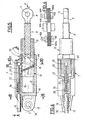
- the mechanical jack 7 of Figures 5 to 10 comprises a screw 8, one end 9 of which is pierced with a buttonhole 11, so as to be able to be articulated on the movable part to be adjusted, or on the fixed part, and a nut 12 pierced d 'an axial housing 13 having a thread 14 adapted to cooperate with the thread 15 of the screw 8.
- the nut 12 is itself housed in a housing or body 16 made integral with one of the two fixed and movable parts by a terminal ear 17 pierced with a buttonhole 18.
- an axial housing 19 receiving the nut 12, and the wall of the housing 19 has a thread 21 adapted to cooperate with threads 22 complementary to the nut 12 formed outside thereof, so as to allow the nut 12 to rotate inside the housing 16 around the general axis XX of the mechanical cylinder 7, under conditions which will be specified below.
- the threads 22 are three in number.
- the device 7 is equipped with means for locking and unlocking the nut 12 in accordance with the invention, making it possible to block the latter in rotation as well as the screw 8 in translation, or on the contrary to release the nut 12 in rotation and thus allow a displacement in axial translation of the screw 8 inside the nut 12.
- the screw 8 being articulated by its end 9 on a movable or fixed part, cannot rotate around of its axis XX, so that when this screw '8 is subjected to an axial thrust F, it can only move in axial translation in the nut 12 if the latter is free to rotate.
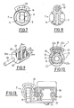
- means for locking the nut 12 comprise: a portion of locking cylinder 23 provided with internal threads 24, 25, 26 conjugate with the threads 22 of the nut 12 (therefore also 3 in this example), and in these two series of threads 22-26 are made respective grooves 22a; 24a, 25a, 26a complementary, parallel to the X-X axis.
- the locking cylinder 23 is housed in a longitudinal compartment 27 of the housing 16, extending parallel to the housing 19.
- the internal thread 21 is interrupted over an angular sector equal to that occupied by the locking cylinder portion 23, as seen in Figure 10.
- the locking cylinder 23 is in an axial position such that its threads 24-26 are in the radial extension of the threads of the thread 21, the threads 24-26 form with those -this a single thread. This therefore allows the rotation of the nut 12 as well as its axial displacement in the housing 16 by cooperation of its threads 22 with the thread 21 put in phase with the threads 24-26.
- the locker 23 is biased by an elastic member 28, constituted by a helical spring coaxial with a cable 29, one end of which is made integral with the locker 23 by a stop 31 disposed in a corresponding recess of the locker 23.
- the cable 29 thus extends in the compartment 27 and passes through the body 16 outside of which it is wrapped in a sheath 32.
- the cable 29 is provided at its end opposite the stop 31 with a control element (not shown), for example a manual handle.
- the spring 28 is supported on a bottom of the compartment 27 and exerts on one end of the locker 23 a thrust substantially parallel to the axis XX, which tends to keep the locker 23 in axial abutment against a retaining means such as a rod 33 partially housed in a corresponding groove on the periphery of the housing 16.
- the housing 27 is dimensioned so as to allow alternating axial displacements of the locker 23 and to guide these displacements by its walls (FIG. 6).
- the operation of the adjustment device 7 is as follows:
- an axial thrust F on the screw 8 results in a double movement: the screw 8 causes the rotation of the nut 12 inside which it sinks by cooperation of the threads 14 and 15, and the nut 12 performs an axial translation in the housing 16 inside which it sinks.
- the axial movements of the locker 23 are guided by the longitudinal walls of the housing 27 (FIG. 10) and likewise the movements of the cable 29 are guided by a corresponding housing on the surface of the locker 23.
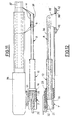
- FIGs 11 to 13 illustrate the installation of an adjustment device 7, according to the embodiment of Figures 5 to 10, by a fastener 20 on a slide 36 which can slide on a slide 37 fixed to a floor, for example of vehicle, for adjusting the longitudinal position of the seat (not shown) of the seat, the jack 7 being positioned at the front of the seat.
- the screw 8 is shown in its position for maximum output from the nut 12, itself in its position for maximum output from the housing 16.
- the end 9 of this screw is articulated on two angles 39, 41 secured to the fixed slide 37, for example by rivets 42.
- Rolling balls 43 are conventionally interposed between the slides 36 and 37.
Landscapes
- Engineering & Computer Science (AREA)
- Mechanical Engineering (AREA)
- General Engineering & Computer Science (AREA)
- Aviation & Aerospace Engineering (AREA)
- Transportation (AREA)
- Transmission Devices (AREA)
- Flexible Shafts (AREA)
- Vehicle Body Suspensions (AREA)
- Seats For Vehicles (AREA)
Claims (3)
Applications Claiming Priority (2)
| Application Number | Priority Date | Filing Date | Title |
|---|---|---|---|
| FR8614179 | 1986-10-13 | ||
| FR8614179A FR2605075B1 (fr) | 1986-10-13 | 1986-10-13 | Systeme de verrouillage d'un dispositif lineaire de reglage rapide et de blocage d'une piece mobile par rapport a une piece fixe |
Publications (2)
| Publication Number | Publication Date |
|---|---|
| EP0265316A1 EP0265316A1 (de) | 1988-04-27 |
| EP0265316B1 true EP0265316B1 (de) | 1990-05-30 |
Family
ID=9339781
Family Applications (1)
| Application Number | Title | Priority Date | Filing Date |
|---|---|---|---|
| EP87402233A Expired - Lifetime EP0265316B1 (de) | 1986-10-13 | 1987-10-07 | Verriegelungssystem für eine lineare Schnellverstell- und Blockiereinrichtung eines beweglichen Teiles gegenüber einem festen Teil |
Country Status (9)
| Country | Link |
|---|---|
| US (1) | US4782715A (de) |
| EP (1) | EP0265316B1 (de) |
| JP (1) | JPS63214553A (de) |
| BR (1) | BR8705428A (de) |
| CA (1) | CA1286893C (de) |
| DE (1) | DE3762988D1 (de) |
| ES (1) | ES2015592B3 (de) |
| FR (1) | FR2605075B1 (de) |
| MX (1) | MX169768B (de) |
Cited By (1)
| Publication number | Priority date | Publication date | Assignee | Title |
|---|---|---|---|---|
| CN102815396A (zh) * | 2011-06-06 | 2012-12-12 | 梅西耶-布加蒂-道提公司 | 可伸缩的致动器 |
Families Citing this family (29)
| Publication number | Priority date | Publication date | Assignee | Title |
|---|---|---|---|---|
| FR2671203B1 (fr) * | 1990-12-26 | 1993-05-21 | Faure Bertrand Automobile | Verin de positionnement a vis et a noyau pivotant evide. |
| DE4405992C2 (de) * | 1994-02-24 | 1996-01-25 | Sifa Sitzfabrik Gmbh | Ruckhemmung |
| US5582461A (en) * | 1994-06-17 | 1996-12-10 | Itt Automotive, Inc. | Infinitely adjustable linear actuator |
| US5556165A (en) * | 1994-06-17 | 1996-09-17 | Pickles; Joseph | Infinitely adjustable linear actuator for vehicle seat |
| DE19529255C2 (de) * | 1995-05-05 | 2000-12-21 | Erwin Hoelle | Arretier- und Verstelleinrichtung |
| US5607032A (en) * | 1995-06-07 | 1997-03-04 | Itt Automotive, Inc. | Rotatable shaft lock apparatus |
| US5689995A (en) * | 1996-02-01 | 1997-11-25 | P. L. Porter Co. | Actuator that adjusts to side loads automatically by pivoting internally |
| US5941130A (en) * | 1998-04-07 | 1999-08-24 | General Motors Corporation | Adjustable steering column for motor vehicle |
| CA2367478A1 (en) * | 1999-04-20 | 2000-10-26 | Kevin N. Tribbett | System for coordinating electrical actuation with the opening of a mechanical lock for vehicle parts |
| FR2810000B1 (fr) | 2000-06-09 | 2004-05-28 | Faure Bertrand Equipements Sa | Siege de vehicule presentant une assise reglable en hauteur |
| FR2845953B1 (fr) | 2002-10-18 | 2005-12-16 | Cresystem | Dispositif de verrouillage de la configuration d'un equipement tel qu'un siege de vehicule |
| US8677562B2 (en) * | 2003-05-02 | 2014-03-25 | William Ernest Taylor Vallance | Movements controlling means |
| GB2401161B (en) * | 2003-05-02 | 2006-09-06 | Titus Internat Ltd | Improvements in movement controls |
| US7556594B2 (en) * | 2005-01-04 | 2009-07-07 | Houston Vincent J | Fitness device |
| WO2006089501A1 (de) * | 2005-02-23 | 2006-08-31 | Luk Lamellen Und Kupplungsbau Beteiligungs Kg | Betätigungsvorrichtung für ein kraftfahrzeug-getriebe, sowie verfahren zur verminderung oder vermeidung von massenträgheitsbedingten steuerungs fehlern bei gangwechselvorgängen |
| US7587956B2 (en) * | 2006-08-29 | 2009-09-15 | Franklin Products, Inc. | Device for controlling motion |
| DE102013202700A1 (de) * | 2012-03-12 | 2013-09-12 | Schaeffler Technologies AG & Co. KG | Planetenwälzgetriebe und Hydrostataktor mit diesem |
| CN103441608A (zh) * | 2013-08-06 | 2013-12-11 | 中国航天科技集团公司第九研究院第七七一研究所 | 一种电动缸防转机构 |
| CN103441607B (zh) * | 2013-08-06 | 2016-08-10 | 中国航天科技集团公司第九研究院第七七一研究所 | 一种矩形缸体电动缸的内防转机构 |
| ES2550369B1 (es) * | 2014-05-05 | 2016-07-21 | Mespack, Sl | Dispositivo automático de cambio de formato para máquina horizontal automática formadora y llenadora de envases flexibles |
| DE102014219256B4 (de) * | 2014-09-24 | 2016-05-04 | Schaeffler Technologies AG & Co. KG | Kugelgewindetrieb |
| WO2017024103A1 (en) | 2015-08-04 | 2017-02-09 | Kyntec Corporation | Mechanical spring actuator |
| US10081325B2 (en) * | 2016-03-07 | 2018-09-25 | Philadelphia Toboggan Coasters, Inc. | Splined lap bar assembly for amusement ride car |
| GB2552509A (en) * | 2016-07-26 | 2018-01-31 | Truck Align London Ltd | Lead screw mechanism |
| DE102018127297B4 (de) * | 2018-10-31 | 2022-03-17 | Witte Automotive Gmbh | Schließbügelanordnung und Verriegelungsvorrichtung |
| US11530561B2 (en) * | 2020-05-13 | 2022-12-20 | Microsoft Technology Licensing, Llc | Variable friction hinged device |
| FR3120926B1 (fr) * | 2021-03-17 | 2023-02-24 | Reel | Dispositif de blocage mecanique d’un mouvement lineaire entre deux structures |
| CN114427804B (zh) * | 2022-02-07 | 2023-08-29 | 四川中陆嘉诚科技有限公司 | 一种用于发射车的自动式射击固定器 |
| CN116624825B (zh) * | 2023-07-25 | 2023-09-26 | 常州星宇车灯股份有限公司 | 三个方向可调的固定结构 |
Family Cites Families (16)
| Publication number | Priority date | Publication date | Assignee | Title |
|---|---|---|---|---|
| US2524481A (en) * | 1941-12-19 | 1950-10-03 | Schermuly Conrad David | Drift release mechanism for presses |
| US2579305A (en) * | 1948-01-26 | 1951-12-18 | Sturgess Inc | Position-adjusting mechanism |
| BE566323A (de) * | 1957-04-03 | 1900-01-01 | ||
| US2933939A (en) * | 1958-12-01 | 1960-04-26 | Gen Motors Corp | Free wheeling ball nut and screw assembly |
| US3046055A (en) * | 1960-02-19 | 1962-07-24 | Anderson Co | Position-adjusting mechanism |
| US3043552A (en) * | 1960-03-03 | 1962-07-10 | Gen Motors Corp | Power transmitting mechanism for vehicle seats |
| US3127788A (en) * | 1960-12-29 | 1964-04-07 | Anderson Co | Position-retaining device |
| DE1429262C3 (de) * | 1963-07-25 | 1974-08-29 | The Anderson Co., Gary, Ind. (V.St.A.) | Einrichtung zum Festlegen der Stellung der einstellbaren Rückenlehne eines Sessels |
| US3246868A (en) * | 1964-07-14 | 1966-04-19 | Anderson Co | Position-retaining device |
| US3356411A (en) * | 1965-02-18 | 1967-12-05 | Lear Siegler Inc | Seat back positioning mechanism |
| US3398986A (en) * | 1966-12-08 | 1968-08-27 | Lear Siegler Inc | Seat positioning mechanism |
| US3436973A (en) * | 1967-06-19 | 1969-04-08 | Kamal Y Aweimrine | Mechanical lock cylinder |
| US3479890A (en) * | 1967-06-29 | 1969-11-25 | Fairchild Hiller Corp | Seat reclining mechanism |
| DE2943694A1 (de) * | 1979-10-30 | 1981-05-14 | Robert Dr.-Ing. 6308 Butzbach Gärtner | Stelleinrichtung mit spindeltrieb |
| US4589301A (en) * | 1983-04-27 | 1986-05-20 | Hoover Universal, Inc. | Linearly infinitely variable mechanism |
| GB8406697D0 (en) * | 1984-03-14 | 1984-04-18 | Teleflex Morse Ltd | Seat recline unit |
-
1986
- 1986-10-13 FR FR8614179A patent/FR2605075B1/fr not_active Expired
-
1987
- 1987-10-07 DE DE8787402233T patent/DE3762988D1/de not_active Expired - Fee Related
- 1987-10-07 ES ES87402233T patent/ES2015592B3/es not_active Expired - Lifetime
- 1987-10-07 EP EP87402233A patent/EP0265316B1/de not_active Expired - Lifetime
- 1987-10-09 BR BR8705428A patent/BR8705428A/pt not_active IP Right Cessation
- 1987-10-13 JP JP62256419A patent/JPS63214553A/ja active Pending
- 1987-10-13 CA CA000549132A patent/CA1286893C/en not_active Expired - Fee Related
- 1987-10-13 MX MX008819A patent/MX169768B/es unknown
- 1987-10-13 US US07/107,696 patent/US4782715A/en not_active Expired - Fee Related
Cited By (2)
| Publication number | Priority date | Publication date | Assignee | Title |
|---|---|---|---|---|
| CN102815396A (zh) * | 2011-06-06 | 2012-12-12 | 梅西耶-布加蒂-道提公司 | 可伸缩的致动器 |
| CN102815396B (zh) * | 2011-06-06 | 2015-02-04 | 梅西耶-布加蒂-道提公司 | 可伸缩的致动器 |
Also Published As
| Publication number | Publication date |
|---|---|
| EP0265316A1 (de) | 1988-04-27 |
| JPS63214553A (ja) | 1988-09-07 |
| CA1286893C (en) | 1991-07-30 |
| BR8705428A (pt) | 1988-05-24 |
| FR2605075B1 (fr) | 1989-01-27 |
| FR2605075A1 (fr) | 1988-04-15 |
| DE3762988D1 (de) | 1990-07-05 |
| ES2015592B3 (es) | 1990-09-01 |
| US4782715A (en) | 1988-11-08 |
| MX169768B (es) | 1993-07-26 |
Similar Documents
| Publication | Publication Date | Title |
|---|---|---|
| EP0265316B1 (de) | Verriegelungssystem für eine lineare Schnellverstell- und Blockiereinrichtung eines beweglichen Teiles gegenüber einem festen Teil | |
| CA3036274A1 (fr) | Outillage de pose d'une fixation aveugle et procede de pose d'une fixation | |
| CA3042195C (fr) | Dispositif de verrouillage a verrou rotatif a commande impulsionnelle | |
| EP2024219A1 (de) | System zur arretierung eines schafts in einer bestimmten lage im verhältnis zu einem anderen schaft unter eliminierung des spielraums zwischen den beiden schäften | |
| FR2953489A1 (fr) | Systeme de fixation d'un siege notamment d'aeronef et siege comportant au moins un tel systeme. | |
| FR2638791A1 (fr) | Verrou pour support d'equipement | |
| FR2594404A1 (fr) | Dispositif de levier pour changement de vitesse de bicyclette | |
| EP1556243B1 (de) | Vorrichtung zum verriegeln der konfiguration einer einrichtung,wie zum beispiel eines fahrzeugsitzes | |
| EP0384838B1 (de) | Einrichtung zur Steuerung der Neigung eines Scheinwerfers | |
| EP0186537B1 (de) | Scheibenbremse | |
| FR2525998A1 (fr) | Verin tele | |
| FR2786520A1 (fr) | Verrou et agencement de ce verrou dans un support | |
| EP0081024B1 (de) | Einrichtung zum wahlweisen Antrieb von Maschinen oder Vorrichtungen durch die Zapfwelle eines landwirtschaftlichen Schleppers | |
| EP0770745B1 (de) | Abnehmbarer Griff für Türen oder Fenster insbesondere in Metallprofilen | |
| FR2574885A1 (fr) | Dispositif de reglage pour frein a disque | |
| FR2468712A1 (fr) | Charniere a blocage selectif | |
| FR2564395A1 (fr) | Enrouleur de ceinture de securite | |
| EP1757829B1 (de) | Vorrichtung zur Erzeugung eines vordefinierten Spannungszustands bei Bedienungsvorrichtung mit einem in eine Führungshülle eingelegten Kabel | |
| EP0225222B1 (de) | Elektrisches Gerät mit verbessertem Zusammenbau | |
| EP0940529A1 (de) | Doppelsicherheitszylinder | |
| EP0869327A1 (de) | Einstellungssystem zur Lagerung und zum Richten eines an einem Träger befestigten Scharfmastes | |
| FR2646938A3 (fr) | Dispositif de commande d'un element regulateur d'un moteur a combustion interne | |
| FR2674148A1 (fr) | Cle avec panneton comportant un element mobile. | |
| EP0625451B1 (de) | Lenkradschloss für Kraftfahrzeuge | |
| FR2507453A1 (fr) | Dispositif de verrouillage d'un dossier de siege, en particulier pour vehicule a moteur |
Legal Events
| Date | Code | Title | Description |
|---|---|---|---|
| PUAI | Public reference made under article 153(3) epc to a published international application that has entered the european phase |
Free format text: ORIGINAL CODE: 0009012 |
|
| AK | Designated contracting states |
Kind code of ref document: A1 Designated state(s): DE ES GB IT SE |
|
| 17P | Request for examination filed |
Effective date: 19880909 |
|
| 17Q | First examination report despatched |
Effective date: 19890106 |
|
| GRAA | (expected) grant |
Free format text: ORIGINAL CODE: 0009210 |
|
| AK | Designated contracting states |
Kind code of ref document: B1 Designated state(s): DE ES GB IT SE |
|
| GBT | Gb: translation of ep patent filed (gb section 77(6)(a)/1977) | ||
| REF | Corresponds to: |
Ref document number: 3762988 Country of ref document: DE Date of ref document: 19900705 |
|
| ITF | It: translation for a ep patent filed | ||
| RAP2 | Party data changed (patent owner data changed or rights of a patent transferred) |
Owner name: ROCKWELL AUTOMOTIVE BODY SYSTEMS-FRANCE EN ABREGE: |
|
| PLBE | No opposition filed within time limit |
Free format text: ORIGINAL CODE: 0009261 |
|
| STAA | Information on the status of an ep patent application or granted ep patent |
Free format text: STATUS: NO OPPOSITION FILED WITHIN TIME LIMIT |
|
| 26N | No opposition filed | ||
| PGFP | Annual fee paid to national office [announced via postgrant information from national office to epo] |
Ref country code: DE Payment date: 19910822 Year of fee payment: 5 |
|
| PGFP | Annual fee paid to national office [announced via postgrant information from national office to epo] |
Ref country code: GB Payment date: 19911001 Year of fee payment: 5 |
|
| PGFP | Annual fee paid to national office [announced via postgrant information from national office to epo] |
Ref country code: ES Payment date: 19911004 Year of fee payment: 5 |
|
| PGFP | Annual fee paid to national office [announced via postgrant information from national office to epo] |
Ref country code: SE Payment date: 19911028 Year of fee payment: 5 |
|
| ITTA | It: last paid annual fee | ||
| PG25 | Lapsed in a contracting state [announced via postgrant information from national office to epo] |
Ref country code: GB Effective date: 19921007 |
|
| PG25 | Lapsed in a contracting state [announced via postgrant information from national office to epo] |
Ref country code: SE Effective date: 19921008 Ref country code: ES Free format text: LAPSE BECAUSE OF THE APPLICANT RENOUNCES Effective date: 19921008 |
|
| GBPC | Gb: european patent ceased through non-payment of renewal fee |
Effective date: 19921007 |
|
| PG25 | Lapsed in a contracting state [announced via postgrant information from national office to epo] |
Ref country code: DE Effective date: 19930701 |
|
| EUG | Se: european patent has lapsed |
Ref document number: 87402233.8 Effective date: 19930510 |
|
| REG | Reference to a national code |
Ref country code: ES Ref legal event code: FD2A Effective date: 20001009 |
|
| PG25 | Lapsed in a contracting state [announced via postgrant information from national office to epo] |
Ref country code: IT Free format text: LAPSE BECAUSE OF NON-PAYMENT OF DUE FEES Effective date: 20051007 |