EP0265391A2 - Régulateur à trois niveaux pour système de conditionnement d'air de véhicules automobiles - Google Patents
Régulateur à trois niveaux pour système de conditionnement d'air de véhicules automobiles Download PDFInfo
- Publication number
- EP0265391A2 EP0265391A2 EP87830325A EP87830325A EP0265391A2 EP 0265391 A2 EP0265391 A2 EP 0265391A2 EP 87830325 A EP87830325 A EP 87830325A EP 87830325 A EP87830325 A EP 87830325A EP 0265391 A2 EP0265391 A2 EP 0265391A2
- Authority
- EP
- European Patent Office
- Prior art keywords
- switches
- cap
- cooling unit
- coolant fluid
- regulator according
- Prior art date
- Legal status (The legal status is an assumption and is not a legal conclusion. Google has not performed a legal analysis and makes no representation as to the accuracy of the status listed.)
- Granted
Links
Images


Classifications
-
- H—ELECTRICITY
- H01—ELECTRIC ELEMENTS
- H01H—ELECTRIC SWITCHES; RELAYS; SELECTORS; EMERGENCY PROTECTIVE DEVICES
- H01H35/00—Switches operated by change of a physical condition
- H01H35/24—Switches operated by change of fluid pressure, by fluid pressure waves, or by change of fluid flow
- H01H35/26—Details
- H01H35/2657—Details with different switches operated at substantially different pressures
-
- B—PERFORMING OPERATIONS; TRANSPORTING
- B60—VEHICLES IN GENERAL
- B60H—ARRANGEMENTS OF HEATING, COOLING, VENTILATING OR OTHER AIR-TREATING DEVICES SPECIALLY ADAPTED FOR PASSENGER OR GOODS SPACES OF VEHICLES
- B60H1/00—Heating, cooling or ventilating devices
- B60H1/00642—Control systems or circuits; Control members or indication devices for heating, cooling or ventilating devices
- B60H1/00814—Control systems or circuits characterised by their output, for controlling particular components of the heating, cooling or ventilating installation
-
- H—ELECTRICITY
- H01—ELECTRIC ELEMENTS
- H01H—ELECTRIC SWITCHES; RELAYS; SELECTORS; EMERGENCY PROTECTIVE DEVICES
- H01H35/00—Switches operated by change of a physical condition
- H01H35/24—Switches operated by change of fluid pressure, by fluid pressure waves, or by change of fluid flow
- H01H35/34—Switches operated by change of fluid pressure, by fluid pressure waves, or by change of fluid flow actuated by diaphragm
Definitions
- the present invention relates in general to air-conditioning systems for motor vehicles, including a cooling unit with coolant fluid and an air-circulation fan connected to an electrical supply circuit.
- the invention relates to a three-level regulator intended to be used with conditioning systems of the type defined above, and including a body containing first, second and third electrical switches connected in the electrical supply circuit of the cooler and the fan of the conditioning system and arranged to activate the cooling unit, activate the fan, and deactivate the cooling unit, respectively.
- the three switches normally include respective fixed contacts and respective movable contacts operated in response to the pressure of the coolant fluid of the cooling unit, and are provided with means for operating the movable contacts of the first, second and third switches differentially in response to increasing response values of the coolant fluid.
- the object of the present invention is to avoid the above inconveniences, and this object is achieved by means of a three-level regulator of the type defined above, characterised in that the three switches are arranged in parallel within the body and each includes a push rod slidable between a retracted rest position and an advanced operating position for controlling the movement of the respective movable contact by the action of a respective substantially cap-shaped elastic member which is normally in an extroverted condition corresponding to the retracted position of the push rod, and is intended to snap into a substantially unstable introverted condition under the pressure of the coolant fluid to cause the rod to advance, the cap-shaped elastic members of the first, second and third switches having differentially increasing elasticity, and auxiliary elastic return means being provided to facilitate the return of the cap-shaped elastic members to the extroverted condition.
- the cap-shaped elastic members preferably consist of metal discs of varying thickness and the auxiliary elastic return means consist of leaf springs acting on the movable contacts.
- an elastically deformable retaining diaphragm is associated with the cap-shaped elastic members and forms a seal between the three switches and the coolant fluid.
- the body comprises a substantially cylindrical, axially flattened casing including a base provided with a threaded tubular connector for connection to the circuit of the cooling unit, a cover carrying the fixed contacts of the three switches, and an intermediate wall which forms a seal between the tubular connector and the cover and has three axial holes through which the push rods of the three switches are slidable.
- the intermediate wall together with the base, defines a pressure chamber and, in axial correspondence with the holes, has three recesses in which the cap-shaped elastic members are peripherally engaged.
- the movable contacts of the three switches consist of three spring plates carried by the cover and pushed against the respective push rods by the auxiliary leaf springs.
- the retaining diaphragm is clamped peripherally between the base and the corresponding face of the intermediate wall, with the interposition of a sealing ring.
- Each of the spring plates constituting the movable contacts is conveniently fixed at one end to the cover by means of a rivet which has one end fixed against the external face of the cover with the interposition of a resilient washer.
- the three-level regulator according to the invention has a series of important advantages compared to conventional regulators, which are summarised below: - the conformation of the three switches allows the bulk of the reducer to be minimised, particularly by virtue of a notable reduction in the axial dimension of the body; - the conformation of the switches ensures small assembly tolerances so that additional final calibrating operations can be eliminated; - the elastic members constituting the movable contacts, formed by two superimposed plates, ensure a high contact pressure when the switch is closed and a high return force during opening; - the rivetting system of the movable contacts, with the interposition of resilient washers, ensures that the contact pressure is maintained even in the presence of high thermal stresses caused by different coefficients of expansion of the materials; - the presence of the sealing ring between the base and the intermediate wall ensures an efficient hermetic seal of the switches, whilst allowing the necessary micrometric sliding of the retaining diaphragm; - the conformation of the body ensures considerable flexibility in the electrical conduction by
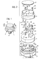
- the three-level regulator includes a substantially cylindrical, axially flattened body 1 consisting of a base, generally indicated 2, and a cover 3, between which an intermediate wall 4 is interposed and clamped.
- the base 2 is generally basin-shaped, with a radial wall 5 facing the intermediate wall 4 and an axial rim 6 which is partially hexagonal in section and whose free end 7 serves to retain the cover 3 by seaming.
- An externally threaded tubular appendage 8 projects from the central region of the wall 5 and acts as a connector for connection of the body 1 to the coolant fluid circuit of the cooling unit of an air-conditioning system for motor vehicles.
- the connection between the body 1 and this circuit is achieved by conventional means, normally downstream of the compressor of the cooling unit with respect to the flow of the coolant fluid, by the screwing of the connector 8 into a corresponding threaded hole by means of a normal spanner engaged with the hexagonal portion of the rim 6.
- the coolant fluid is admitted, through the tubular connector 8, to an axially-restricted pressure chamber 9 between the wall 5 of the base 2 and the facing surface of the intermediate wall 4.
- the pressure chamber is sealed from the remaining part of the body 1 by means of an elastically deformable diaphragm 10 whose outer edge is gripped between the wall 5 of the base 2 and the intermediate wall 4, with the interposition of a sealing ring 11 able to permit micrometric radial sliding of the diaphragm 10 during its deformation.
- This diaphragm 10 is normally of a substantially-inextensible, heat- and wear-resistant plastics material, for example, a sheet of polyimide known commercially as KAPTON.
- a protective cap 12 is also applied to the external side of the cover 3 and can be removed to allow the regulator to be connected to the electrical supply circuit of the cooling unit and air-circulation fan of the conditioning system for motor vehicles, in the manner explained below.
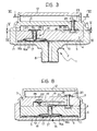
- first, second and third switches which are arranged in parallel and generally indicated 13, 14, 15 respectively in Figures 7, 3 and 8, 9.
- the three switches have various components which are identical (except, perhaps, for their dimensions) and, for simplicity, are indicated with the same reference numerals in the drawings.
- These components include a push rod 20 which can slide through an axial hole 17 in the intermediate wall 4 between a retracted rest position, illustrated in the above-mentioned Figures, and an advanced operating position, illustrated in broken outline in Figure 8 with reference to the second switch 14.
- each push rod 20 nearest the wall 5 of the base 2 bears against a respective cap-shaped elastic member 16 and its other end bears against the free end of the spring plate 18 which acts as a movable contact and whose opposite end is fixed to the cover 3 in a manner made clear below.
- Each movable contact 18 is associated with a respective leaf spring 19 which tends to hold the plate 18 against the surface of the intermediate wall 4 facing the cover 3, towards the corresponding end of the respective push rod 20.
- the cap-shaped elastic members 16 consist of metal discs normally arranged in the extroverted condition illustrated in the drawings, and held by the diaphragm 10 in peripheral engagement against the edges of respective recesses 21 formed in the surface of the intermediate wall 4 facing the wall 5 of the base 2.
- the cap-shaped elastic members 16 are able to snap-deform from the extroverted condition illustrated, which corresponds to the retracted rest position of the push rods 20, to take up a substantially unstable introverted condition in which they withdraw into their respective recesses 21.
- the push rods 20 are obviously moved from the retracted position to the advanced operating position and the respective movable contacts 18 thus snap into place against the action of the leaf springs 19.
- the above-described deformation of the elastic members 16 is brought about, in use, by the effect of the pressure of the coolant fluid supplied to the pressure chamber 9 through the tubular connector 8.
- the three cap-shaped elastic members 16 have differential elasticities.
- the elastic member 16 of the first switch 13 has a low rigidity so that it deforms from the extroverted condition to the introverted condition at pressures of the order of 2 bars
- the elastic member 16 of the second switch 14 has a medium rigidity so as to deform at a pressure value of the order of 13 - 14 bars
- the elastic member 16 of the switch 16 has a high rigidity so as to deform when the pressure reaches very high values, of the order of 30 bars.
- the metal discs which constitute the elastic members 16 can be made with different thicknesses (reduced for the first switch 13, medium for the second switch 14, and increased for the third switch 15) and/or, as in the case of the example illustrated, with the use of a single disc 16a for the first switch 13, two superimposed discs 16a, 16b for the second switch 14, and three superimposed discs 16a, 16b, 16c for the third switch 15.
- the spring plates 18 which, as stated, constitute the movable contacts of the three switches 13, 14, 15 are fixed to the cover 3, at their ends opposite the ends which are held against the respective push rods 20, by means of three rivets 23. These rivets 23 pass through corresponding axial holes 24 formed in the cover 3 and are fixed at their ends against the external face of this cover 3, with the interposition of respective resilient washers 25. These resilient washers 25 allow any play to be taken up and ensure a correct anchorage of the movable contacts 18 and the relative leaf springs 19, in use, even in the presence of high thermal stresses caused by different coefficients of expansion of the materials.
- the free ends of the plates 18 cooperate with corresponding fixed contacts carried by the cover 3.
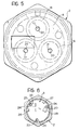
- These fixed contacts include a substantially Z-shaped plate 26 which cooperates at one end with the movable contact 18 of the first switch 175 and at the other end is permanently connected to the movable contact 18 of the third switch 15, like a bridge, through the respective rivet 23, a first U-shaped plate 27 intended to cooperate with the movable contact 18 of the second switch 14, and a second U-shaped plate 28 intended to cooperate with the movable contact 18 of the third switch 15.
- the arrangement of the fixed contacts 26, 27 and 28 is such that the first and second switches 13, 14 are normally open (that is, the corresponding movable contacts 18 are spaced from the relative fixed contacts 26 and 27 in the extroverted condition of the corresponding elastic members 16), as indicated in Figures 7 and 8 respectively, whilst the third switch 15 is normally closed (that is, the relative movable contact 18 is closed onto the fixed contact 28 in the extroverted condition of the corresponding elastic member 16), as illustrated in Figure 10.
- Two connecting terminals are fixed to the external face of the cover 3 by means of the rivets 23 associated with the movable contacts 18 of the first and second switches 13, 14 respectively.
- the connectors 29 and 30 are accessible from the outside, through the cap 12, for connection to the electrical supply circuit of the fan for the forced circulation of air and the compressor of the cooling unit of a conditioning system for motor vehicles, respectively.
- the operation of the three switches 13, 14 and 15 is sequential, in response to increasing pressure values of the coolant fluid supplied to the pressure chamber 9 of the body 1 through the tubular connector 8.
- the disc 16a of the elastic member 16 of the first switch 13 changes from the extroverted condition to the introverted condition, which causes, by means of the respective push rod 20, the closure of the corresponding movable contact 18 onto the bridge 26 and the consequent activation of the compressor of the cooling unit through the normally-closed switch 15.
- the attainment of a pressure of the order of 13-14 bars causes the two discs 16a and 16b making up the elastic member 16 of the second switch 14 to change from the extroverted condition to the introverted condition and, through the respective push rod 20, the consequent closure of the corresponding movable contact 18 onto the fixed contact 27 so as to cause the intervention of the air-circulation fan.
- the three discs 16a, 16b, 16c making up the elastic member 16 of the third switch 15 would change from the extroverted condition to the introverted condition and cause, through the respective push rod 20, the corresponding movable contact 18 to move away from the fixed contact 28, thus deactivating the compressor of the cooling unit.
- the elastic members 16 snap back from the introverted condition to the extroverted condition when the pressure of the coolant fluid falls below their respective calibration values, with the help of the elastic thrust of the spring 19.
- the regulator according to the invention as well as being particularly simple and functional both from the point of view of production and from the point of view of operation, has a greatly reduced bulk which facilitates its installation in motor vehicles.
- This installation is further simplified by virtue of the easy external connection of the regulator, which can conveniently be adapted to different requirements by acting only on its connection terminals accessible through the cap 12, without requiring structural modification of the regulator.
Landscapes
- Physics & Mathematics (AREA)
- Fluid Mechanics (AREA)
- Thermal Sciences (AREA)
- Engineering & Computer Science (AREA)
- Mechanical Engineering (AREA)
- Motor Or Generator Cooling System (AREA)
- Switches Operated By Changes In Physical Conditions (AREA)
- Air-Conditioning For Vehicles (AREA)
Applications Claiming Priority (2)
| Application Number | Priority Date | Filing Date | Title |
|---|---|---|---|
| IT8667790A IT1216456B (it) | 1986-10-20 | 1986-10-20 | Regolatore a tre livelli per impianti di condizionamento dell aria per autoveicoli |
| IT6779086 | 1986-10-20 |
Publications (3)
| Publication Number | Publication Date |
|---|---|
| EP0265391A2 true EP0265391A2 (fr) | 1988-04-27 |
| EP0265391A3 EP0265391A3 (en) | 1989-08-16 |
| EP0265391B1 EP0265391B1 (fr) | 1991-11-13 |
Family
ID=11305314
Family Applications (1)
| Application Number | Title | Priority Date | Filing Date |
|---|---|---|---|
| EP87830325A Expired EP0265391B1 (fr) | 1986-10-20 | 1987-09-09 | Régulateur à trois niveaux pour système de conditionnement d'air de véhicules automobiles |
Country Status (4)
| Country | Link |
|---|---|
| EP (1) | EP0265391B1 (fr) |
| DE (2) | DE3774533D1 (fr) |
| ES (1) | ES2002251T3 (fr) |
| IT (1) | IT1216456B (fr) |
Cited By (3)
| Publication number | Priority date | Publication date | Assignee | Title |
|---|---|---|---|---|
| EP0359980A3 (fr) * | 1988-09-20 | 1991-01-30 | SICEB S.p.A. | Capteur de pression pour mesurer la pression d'un fluide spécialement pour la mesure d'une pression d'huile |
| EP0542695A3 (en) * | 1991-11-15 | 1993-07-28 | Ma-Ter S.R.L. | Touch pressure switch including a manually operated safety microswitch |
| EP0692804A1 (fr) * | 1994-07-14 | 1996-01-17 | BITRON S.p.A. | Régulateur à quatre niveaux pour systèmes de conditionnement d'air actionnés par fluide |
Family Cites Families (5)
| Publication number | Priority date | Publication date | Assignee | Title |
|---|---|---|---|---|
| US3187136A (en) * | 1961-10-16 | 1965-06-01 | Robertshaw Controls Co | Multiple pressure switch construction |
| US3786210A (en) * | 1972-08-29 | 1974-01-15 | Fasco Industries | Sequentially actuated pressure switches having separate resistor elements associated with each |
| US4458117A (en) * | 1982-08-25 | 1984-07-03 | General Electric Company | Control device and methods of operating such |
| DE8422298U1 (de) * | 1984-07-26 | 1984-10-25 | Ranco Inc., 43017 Dublin, Ohio | Druckschalter |
| US4591677A (en) * | 1985-02-07 | 1986-05-27 | Tgk Company, Limited | Three-function pressure switch |
-
1986
- 1986-10-20 IT IT8667790A patent/IT1216456B/it active
-
1987
- 1987-09-09 EP EP87830325A patent/EP0265391B1/fr not_active Expired
- 1987-09-09 DE DE8787830325T patent/DE3774533D1/de not_active Expired - Fee Related
- 1987-09-09 DE DE198787830325T patent/DE265391T1/de active Pending
- 1987-09-09 ES ES198787830325T patent/ES2002251T3/es not_active Expired - Lifetime
Cited By (3)
| Publication number | Priority date | Publication date | Assignee | Title |
|---|---|---|---|---|
| EP0359980A3 (fr) * | 1988-09-20 | 1991-01-30 | SICEB S.p.A. | Capteur de pression pour mesurer la pression d'un fluide spécialement pour la mesure d'une pression d'huile |
| EP0542695A3 (en) * | 1991-11-15 | 1993-07-28 | Ma-Ter S.R.L. | Touch pressure switch including a manually operated safety microswitch |
| EP0692804A1 (fr) * | 1994-07-14 | 1996-01-17 | BITRON S.p.A. | Régulateur à quatre niveaux pour systèmes de conditionnement d'air actionnés par fluide |
Also Published As
| Publication number | Publication date |
|---|---|
| IT1216456B (it) | 1990-02-28 |
| EP0265391B1 (fr) | 1991-11-13 |
| ES2002251T3 (es) | 1992-07-01 |
| DE3774533D1 (de) | 1991-12-19 |
| IT8667790A0 (it) | 1986-10-20 |
| DE265391T1 (de) | 1988-09-22 |
| ES2002251A4 (es) | 1988-08-01 |
| EP0265391A3 (en) | 1989-08-16 |
Similar Documents
| Publication | Publication Date | Title |
|---|---|---|
| US5854455A (en) | Switching device with secondary switching function | |
| US4306211A (en) | Heat operated protective switch | |
| US5897055A (en) | Actuator with an electrically heatable thermostatic operating element | |
| US6300860B1 (en) | Switch having an insulating support | |
| US4400601A (en) | Combination switch and valve device | |
| EP0265391A2 (fr) | Régulateur à trois niveaux pour système de conditionnement d'air de véhicules automobiles | |
| US5061832A (en) | Field settable differential pressure switch assembly for low fluid pressure applications | |
| US4703140A (en) | Electric circuit controlling device | |
| US3535480A (en) | Pressure sensitive switch | |
| US4458117A (en) | Control device and methods of operating such | |
| GB2137317A (en) | Control valve for radiators | |
| US4510763A (en) | Automotive type air conditioning system and method of operating such | |
| US4532389A (en) | Electric circuit controlling device and method of operating | |
| US4200776A (en) | Control device with grain oriented snap disk | |
| US3735069A (en) | Snap-action electric switch | |
| US3602863A (en) | Adjustable thermostat | |
| US4231010A (en) | Thermostatic switch employing a stud member for calibration of the switch | |
| US4410776A (en) | Control device | |
| EP0565028B1 (fr) | Commutateur à pression | |
| US4287780A (en) | Snap-action member | |
| EP0576388B1 (fr) | Interrupteur de freinage multicircuit autoajustable | |
| US4614849A (en) | Electrical pressure switch | |
| JPS62100918A (ja) | 電気式の圧力スイツチ | |
| US4551702A (en) | Thermostatic switch and method of manufacture | |
| US4351105A (en) | Method of making a control device |
Legal Events
| Date | Code | Title | Description |
|---|---|---|---|
| PUAI | Public reference made under article 153(3) epc to a published international application that has entered the european phase |
Free format text: ORIGINAL CODE: 0009012 |
|
| AK | Designated contracting states |
Kind code of ref document: A2 Designated state(s): DE ES FR GB SE |
|
| EL | Fr: translation of claims filed | ||
| DET | De: translation of patent claims | ||
| PUAL | Search report despatched |
Free format text: ORIGINAL CODE: 0009013 |
|
| AK | Designated contracting states |
Kind code of ref document: A3 Designated state(s): DE ES FR GB SE |
|
| RAP1 | Party data changed (applicant data changed or rights of an application transferred) |
Owner name: SICEB S.P.A. |
|
| 17P | Request for examination filed |
Effective date: 19891011 |
|
| 17Q | First examination report despatched |
Effective date: 19900625 |
|
| GRAA | (expected) grant |
Free format text: ORIGINAL CODE: 0009210 |
|
| AK | Designated contracting states |
Kind code of ref document: B1 Designated state(s): DE ES FR GB SE |
|
| REF | Corresponds to: |
Ref document number: 3774533 Country of ref document: DE Date of ref document: 19911219 |
|
| ET | Fr: translation filed | ||
| REG | Reference to a national code |
Ref country code: ES Ref legal event code: FG2A Ref document number: 2002251 Country of ref document: ES Kind code of ref document: T3 |
|
| PLBE | No opposition filed within time limit |
Free format text: ORIGINAL CODE: 0009261 |
|
| STAA | Information on the status of an ep patent application or granted ep patent |
Free format text: STATUS: NO OPPOSITION FILED WITHIN TIME LIMIT |
|
| 26N | No opposition filed | ||
| EAL | Se: european patent in force in sweden |
Ref document number: 87830325.4 |
|
| PGFP | Annual fee paid to national office [announced via postgrant information from national office to epo] |
Ref country code: SE Payment date: 20010731 Year of fee payment: 15 |
|
| PGFP | Annual fee paid to national office [announced via postgrant information from national office to epo] |
Ref country code: GB Payment date: 20010817 Year of fee payment: 15 |
|
| PGFP | Annual fee paid to national office [announced via postgrant information from national office to epo] |
Ref country code: DE Payment date: 20010820 Year of fee payment: 15 |
|
| PGFP | Annual fee paid to national office [announced via postgrant information from national office to epo] |
Ref country code: ES Payment date: 20010829 Year of fee payment: 15 |
|
| PGFP | Annual fee paid to national office [announced via postgrant information from national office to epo] |
Ref country code: FR Payment date: 20010928 Year of fee payment: 15 |
|
| REG | Reference to a national code |
Ref country code: GB Ref legal event code: IF02 |
|
| PG25 | Lapsed in a contracting state [announced via postgrant information from national office to epo] |
Ref country code: GB Free format text: LAPSE BECAUSE OF NON-PAYMENT OF DUE FEES Effective date: 20020909 |
|
| PG25 | Lapsed in a contracting state [announced via postgrant information from national office to epo] |
Ref country code: SE Free format text: LAPSE BECAUSE OF NON-PAYMENT OF DUE FEES Effective date: 20020910 Ref country code: ES Free format text: LAPSE BECAUSE OF NON-PAYMENT OF DUE FEES Effective date: 20020910 |
|
| PG25 | Lapsed in a contracting state [announced via postgrant information from national office to epo] |
Ref country code: DE Free format text: LAPSE BECAUSE OF NON-PAYMENT OF DUE FEES Effective date: 20030401 |
|
| GBPC | Gb: european patent ceased through non-payment of renewal fee |
Effective date: 20020909 |
|
| EUG | Se: european patent has lapsed | ||
| PG25 | Lapsed in a contracting state [announced via postgrant information from national office to epo] |
Ref country code: FR Free format text: LAPSE BECAUSE OF NON-PAYMENT OF DUE FEES Effective date: 20030603 |
|
| REG | Reference to a national code |
Ref country code: FR Ref legal event code: ST |
|
| REG | Reference to a national code |
Ref country code: ES Ref legal event code: FD2A Effective date: 20031011 |