EP0265410A2 - Lade- und -Entladegerät für Plattenspieler - Google Patents
Lade- und -Entladegerät für Plattenspieler Download PDFInfo
- Publication number
- EP0265410A2 EP0265410A2 EP87870143A EP87870143A EP0265410A2 EP 0265410 A2 EP0265410 A2 EP 0265410A2 EP 87870143 A EP87870143 A EP 87870143A EP 87870143 A EP87870143 A EP 87870143A EP 0265410 A2 EP0265410 A2 EP 0265410A2
- Authority
- EP
- European Patent Office
- Prior art keywords
- drawer
- record disc
- support
- loading
- movement
- Prior art date
- Legal status (The legal status is an assumption and is not a legal conclusion. Google has not performed a legal analysis and makes no representation as to the accuracy of the status listed.)
- Granted
Links
Images



Classifications
-
- G—PHYSICS
- G11—INFORMATION STORAGE
- G11B—INFORMATION STORAGE BASED ON RELATIVE MOVEMENT BETWEEN RECORD CARRIER AND TRANSDUCER
- G11B17/00—Guiding record carriers not specifically of filamentary or web form, or of supports therefor
- G11B17/02—Details
- G11B17/04—Feeding or guiding single record carrier to or from transducer unit
-
- G—PHYSICS
- G11—INFORMATION STORAGE
- G11B—INFORMATION STORAGE BASED ON RELATIVE MOVEMENT BETWEEN RECORD CARRIER AND TRANSDUCER
- G11B17/00—Guiding record carriers not specifically of filamentary or web form, or of supports therefor
- G11B17/02—Details
- G11B17/04—Feeding or guiding single record carrier to or from transducer unit
- G11B17/05—Feeding or guiding single record carrier to or from transducer unit specially adapted for discs not contained within cartridges
- G11B17/053—Indirect insertion, i.e. with external loading means
- G11B17/056—Indirect insertion, i.e. with external loading means with sliding loading means
-
- G—PHYSICS
- G11—INFORMATION STORAGE
- G11B—INFORMATION STORAGE BASED ON RELATIVE MOVEMENT BETWEEN RECORD CARRIER AND TRANSDUCER
- G11B17/00—Guiding record carriers not specifically of filamentary or web form, or of supports therefor
- G11B17/02—Details
- G11B17/022—Positioning or locking of single discs
- G11B17/028—Positioning or locking of single discs of discs rotating during transducing operation
- G11B17/035—Positioning by moving the loading station
Definitions
- the present invention relates to an apparatus for loading and unloading record discs in record disc players and, more particularly, to apparatus for record discs carrying what is known as optical information, the reproduction of which is effected by laser.
- One type of such record discs now widely provided in home music systems, as well as in other applications, is known as compact record disc or "CD" record disc.
- record disc players having a turntable adapted to drive compact record discs in a horizontal plane are generally provided with a loading and unloading mechanism having a drawer in which the user deposits the record disc with its recorded face in a horizontal plane, an arrangement which prompts the user to handle the record disc by its periphery, the record disc being positioned with precision in a centering recess provided in the bottom of the drawer.
- a control knob provided for this purpose is actuated or a slight pressure is exerted on the front face of the drawer which is then displaced toward the interior of the apparatus by motorized means.
- the drawer At the end of the reproduction period or by a control means actuated by the user, the drawer is displaced outwardly and brings the record disc back to a loading/unloading position within reach of the user who recovers it by grasping it by its periphery, cut-out portions or depressions provided in the bottom of the drawer facilitating the user grasping the record disc by its periphery.
- the main object of the present invention is to provide a remedy for the above disadvantage while retaining and even increasing the advantages of loading and unloading mechanism of the type which has a drawer.
- An additional object is to make the loading and unloading of the record disc particularly easy in general in disc-playing apparatus equipped with a loading drawer.
- Another object is to achieve the advantages enumerated above with complete reliability and by simple, and easily produced apparatus which, therefore, has a low cost.
- the loading drawer is provided with a support means which, in the external loading/unloading position of the drawer, raises the record disc to an inclined position in relation to the drawer, the record disc facing the user, which facilitates the user gripping the record disc at its edges for placing it in or removing it from the drawer.
- the record disc is pivoted into a substantially horizontal position which permits its loading by the horizontal displacement of the drawer.
- the record disc is again raised to an inclined position in relation to the drawer, facing the user.
- the support means for raising and lowering the record disc preferably embodies a support pivoting about a horizontal axis, the support assuming the raised and lowered positions under the action of control means operating either in the course of an extension of the travel of the drawer beyond that necessary for the complete removal of the record disc or after the stoppage of this travel.
- means are provided which further increase the ease of loading, particularly by enabling the drawer to be controlled by a pressure exerted on the record disc after it has been placed in position.
- an intermediate position is provided for the pivoting support with the object of enabling it to serve to deposit the record disc on the driving turntable.
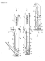
- Figures 1 and 2 illustrate the conventional drawer-type front loading/unloading mechanism with the drawer 22 respectively in the external and internal positions in relation to the fixed housing 34 of the apparatus.
- the drawer 22 In the external position, the drawer 22 has a recess or depression 24 which is accessible from above for receiving the record disc 26 in a horizontal position on retractable supports 28 which hold it at a level enabling it to pass over the centering spindle 30 of the turntable 32 of the record disc player when the drawer is displaced towards the interior of the housing 34.
- a mechanism controlled by a switch provided for this purpose or by a switch reacting to a pressure exerted on the drawer drives the drawer 22 by means of a rack 36 rigidly connected to the drawer and a motorized pinion (not shown), the drawer being guided by guides 38 into its extreme internal position ( Figure 2) where the record disc 26, after having been brought with precision above the turntable 32, has been lowered onto the turntable following the downward movement of the supports 28 by means coming into action at the end of the inward horizontal travel of the drawer.
- the various steps take place in reverse, the record disc 26 is raised by the supports 28 to a level at which it does not interfere with the centering spindle 30, and the drawer 22 is then displaced out of the housing 34 toward its external position, illustrated in Figure 1, in which the record disc can be removed by the user.
- Figures 3, 4 and 5 illustrate a first embodiment of the invention in which the travel of the drawer 22 is extended outwards to an external loading/unloading position and in which the drawer is supported for horizontal movement to an intermediate position and an extreme internal operating position, carrying a record disc from a loading/unloading position on the turntable 32.
- support means are carried on the drawer 22 and are engageable with a record disc 26 on the drawer for tilting the record disc into an inclined position facing upwardly and forwardly toward a front portion of the drawer when the drawer is in the loading/unloading position, as illustrated in Figure 3.
- the support means is provided by a support 40 which pivots about a horizontal axle 41 which is mounted transversally in relation to the drawer 22, this axle 41 being situated close to the front face of the drawer. In the raised position of Figure 3, this support 40 occupies an inclined position in relation to the drawer 22.
- An actuating means is provided including a stud 42 formed on an arm 44 of the support 40 which is engaged by a stop 46 provided at the end of a slide 48 supported on the drawer 22 and having a second stop 50 at the opposite end engageable with a fixed member 52 of the housing 34.
- the slide 48 is guided by studs 54 on the drawer 22 and can be displaced longitudinally due to slots 56 receiving the studs 54.
- the second stop 50 limits the outward travel of the slide 48 accompanying the displacement of the drawer 22 and the slide 48 through the first stop 46 pivots the support 40 against the force of the return spring 58 as the drawer 22 continues its outward movement after the slide movement has been stopped.
- the pivoting support 40 constitutes a means for supporting the record disc in the front portion of the recess 24 adjacent to the front of the drawer and in an inclined plane with the top surface of the record disc facing towards the front of the drawer and facing towards a user. In this position, if the plane of the record disc were to be extended towards the user, it would incline downwardly.
- the support 40 holds the record disc in this inclined or tilted position.
- the drawer 22 is moved "in" towards its internal position where the record disc is placed on the turntable, as in existing apparatus.
- the means provided in the embodiments described above permit the same slight displacement of the drawer necessary to start the drive means of the drawer following a slight pressure exerted not only on the drawer but also on the pivoting support in the raised position, particularly through the intervention of the record disc.
- FIGS 6 to 10 show another practical embodiment of the invention according to which the drawer 22 retains its normal outward travel.
- a rack 66 is provided which is rigidly connected to a slide 68 carried by studs 70 fixed to the lateral side of the drawer 22.
- the slide 68 can be displaced longitudinally in relation to the drawer due to slots 72 which receive the studs 70.
- the front position of the slide 68 is further equipped with an inclined ramp 74 which acts on a pin 76 rigidly connected to the support 78 pivoting about an axle 80.
- locking means are provided for connecting and disconnecting the slide 68 carrying the rack 66 and the drawer 22.
- This locking means comprises, in the disclosed embodiment, a pin 82 carried by a lever 84 pivoting about a pin 86 rigidly connected to the drawer 22.
- the pin 82 can engage in a notch 88 provided in the slide 68 in order to lock the slide 68 to the drawer 22 or can be disengaged from the notch 88 in the slide 68 to unlock the slide from the drawer.
- the lever 84 In order to control the movement of the lever 84 and the pin 82, the lever 84 likewise carries a stud 90 which cooperates with a cut-out 92 in the form of a ramp provided in a cross piece 94 rigidly connected to the housing 34 of the apparatus.
- the lever 84 is further equipped with a resilient tongue 96 bearing against a stop 98 rigidly connected to the drawer 22 in such a manner as to exert a permanent thrust of the pin 82 toward the slide 68 and hence toward the notch 88
- the stud 90 engages in the cut-out 92 which causes the pivoting of the lever 84 and the emergence of the pin 82 from the notch 88 against the action of the resilient tongue 96. From then on, the rack 66 and the slide 68 are disconnected from the drawer 22 and can continue their outward movement, still driven by the pinion 100 (Figs 6, 7).
- a stud 102 provided on the drive pinion 100 acts on a swith 104 to interrupt the feed of current to the electric motor (not shown) driving this pinion 100.
- the record disc is lowered to a safe, non-interfering position during both the loading and unloading operations.
- Figure 11 represents a modification of the embodiment described above in that the slide 68 carries, at its front portion, a link 106 articulated on the slide 68 at a pin 108 and connected by its other end to the stud 76 of the support 78.
- the travel of the stud 76 is limited in accordance with a slot 110 in the form of an arc of a circle.
- known record disc player apparatus are generally equipped with retractable supports 28 which, during the horizontal displacement of the drawer 22, hold the record disc 26 at a raised level, enabling it to pass over the centering spindle 30 of the turntable 32 of the record disc player.
- Figure 12 shows the front loading drawer 22 in the extreme external loading/unloading position in relation to the housing 34.
- the record disc 26 is held, in accordance with this invention, in an inclined position by the support 112. Following initiation of a loading operation for placing the record disc 26 on the turntable 32 in operating position for reproduction, the record disc has been lowered into a substantially horizontal position which nevertheless allows it to pass through the opening 60 formed in the front of the housing 34.
- Figures 15 to 17 show an example of a practical embodiment of such a mechanism wherein elements are provided to act on the pivotable support 112 for a record disc in order to cause its downward movement (Figure 16), herein shown as vertical projections 113 carried by a bridge 114 pivoting vertically about a pin 116 carried by the housing under the action of a spring 118.
- the brigde carries, at the end opposite its pivot point a holder 120 for a magnetic ring 122 adapted to cooperate with the turntable 32 and its spindle 30 to clamp the record disc on the turntable when the drawer 22 has reached its extreme internal position, and this bridge 114 is released by the loading mechanism to the action of its spring 118.
- the drawer 22 carries a record disc 26 held by the pivotable support 112 and a slide 126 carrying the rack 66.
- the slide 126 has a ramp 128 cooperating with a stud 130 on the support 112.
- the support 112 is pivotable about the axle 132.
- a vertical slot 136 has been provided, extending the oblique ramp 128 downwards and enabling the stud 130 to move down at the desired moment.
- Figure 15 shows the drawer 22 in its extreme internal position, the record disc 26 having passed over the turntable spindle 30.
- the pivoting bridge 114 is then lowered ( Figures 16 and 17), and the vertical projection 113 acts on the stud 130 in such a manner as to push it to the end of the vertical slot 136 against the action of the leaf spring 134.
- the support 112 is lowered completely and held in a horizontal position below the record disc while the record disc 26 is clamped on the turntable 32 by the magnetic ring 120.
- the pinion 100 reaches its positon of rest, the stud 102 having actuated the switch 104 in the other direction, and the record disc 26 is set in rotation for the reproduction of the information which it carries.
Landscapes
- Feeding And Guiding Record Carriers (AREA)
Applications Claiming Priority (2)
| Application Number | Priority Date | Filing Date | Title |
|---|---|---|---|
| BE0/217321A BE905639A (fr) | 1986-10-22 | 1986-10-22 | Dispositif de chargement et de dechargement de disques dans les tourne-disques. |
| BE905639 | 1986-10-22 |
Publications (3)
| Publication Number | Publication Date |
|---|---|
| EP0265410A2 true EP0265410A2 (de) | 1988-04-27 |
| EP0265410A3 EP0265410A3 (de) | 1989-07-19 |
| EP0265410B1 EP0265410B1 (de) | 1992-04-08 |
Family
ID=3844091
Family Applications (1)
| Application Number | Title | Priority Date | Filing Date |
|---|---|---|---|
| EP8787870143A Expired - Lifetime EP0265410B1 (de) | 1986-10-22 | 1987-10-14 | Lade- und -Entladegerät für Plattenspieler |
Country Status (4)
| Country | Link |
|---|---|
| US (1) | US4811323A (de) |
| EP (1) | EP0265410B1 (de) |
| JP (1) | JPH0695421B2 (de) |
| KR (1) | KR950003990B1 (de) |
Families Citing this family (4)
| Publication number | Priority date | Publication date | Assignee | Title |
|---|---|---|---|---|
| NL8702604A (nl) * | 1987-11-02 | 1989-06-01 | Philips Nv | Platenspeler met een laadinrichting voor het laden van een op een plaatdrager aanwezige plaat. |
| BE1001702A6 (fr) * | 1988-06-03 | 1990-02-13 | Staar Dev Co Sa | Systeme de changeur automatique pour supports d'informations. |
| JPH11213513A (ja) * | 1998-01-26 | 1999-08-06 | Teac Corp | 記録媒体装着装置 |
| US20040098735A1 (en) * | 2002-11-14 | 2004-05-20 | Lg Electronics Inc. | Disk loading apparatus for a disk drive |
Family Cites Families (13)
| Publication number | Priority date | Publication date | Assignee | Title |
|---|---|---|---|---|
| NL169408C (nl) * | 1972-04-18 | 1982-07-16 | Idn Invention Dev Novelties | Opberginrichting omvattend een gestel met vakken voor het opnemen van schuifladen, in het bijzonder voor het opbergen van geluids- en beeldbandcassettes. |
| US4403317A (en) * | 1980-04-22 | 1983-09-06 | Sharp Kabushiki Kaisha | Automated disk mount assembly |
| JPS5783503U (de) * | 1980-11-11 | 1982-05-24 | ||
| BE891132R (fr) * | 1981-04-17 | 1982-03-16 | Staar Sa | Appareil enregistreur et/ou reproducteur d'informations portees par un support en forme de disque |
| JPS5814386A (ja) * | 1981-07-20 | 1983-01-27 | Toshiba Corp | デジタルデイスクプレ−ヤ装置 |
| US4439852A (en) * | 1982-05-03 | 1984-03-27 | Rca Corporation | Disc player having record handling apparatus |
| US4561084A (en) * | 1982-06-04 | 1985-12-24 | Hitachi, Ltd. | Disk loading and unloading system |
| JPS59207054A (ja) * | 1983-05-09 | 1984-11-24 | Hitachi Ltd | 記録円盤の装着装置 |
| NL8302129A (nl) * | 1983-06-15 | 1985-01-02 | Philips Nv | Platenspeler met een laadmechanisme voor het laden van een plaat. |
| CA1228030A (en) * | 1983-06-15 | 1987-10-13 | Petrus L.A. Rouws | Disc-record player comprising a disc-loading mechanism and disc holder for use in such a player |
| DE3505339A1 (de) * | 1984-02-17 | 1985-08-29 | Pioneer Electronic Corp., Tokio/Tokyo | Wechselmechanismus |
| US4706237A (en) * | 1984-10-05 | 1987-11-10 | U.S. Philips Corporation | Disc player with strobe light illumination |
| BE1000472A4 (fr) * | 1987-04-13 | 1988-12-20 | Staar Sa | Dispositif automatique de chargement de disques de diametres differents sur les plateaux rotatifs de tourne-disques. |
-
1987
- 1987-09-24 US US07/100,621 patent/US4811323A/en not_active Expired - Lifetime
- 1987-10-14 EP EP8787870143A patent/EP0265410B1/de not_active Expired - Lifetime
- 1987-10-22 KR KR1019870011719A patent/KR950003990B1/ko not_active Expired - Fee Related
- 1987-10-22 JP JP62265497A patent/JPH0695421B2/ja not_active Expired - Lifetime
Also Published As
| Publication number | Publication date |
|---|---|
| KR950003990B1 (ko) | 1995-04-21 |
| JPS63179460A (ja) | 1988-07-23 |
| EP0265410B1 (de) | 1992-04-08 |
| JPH0695421B2 (ja) | 1994-11-24 |
| KR880005597A (ko) | 1988-06-29 |
| EP0265410A3 (de) | 1989-07-19 |
| US4811323A (en) | 1989-03-07 |
Similar Documents
| Publication | Publication Date | Title |
|---|---|---|
| US5067121A (en) | Disc-record player comprising a disc-loading device for a disc supported on a tray | |
| US4773057A (en) | Apparatus for reproducing selectively loaded discs of different diameters | |
| US4839880A (en) | Apparatus for loading record discs of different diameters in disc players | |
| EP0356984A2 (de) | Plattenspieler | |
| JPS6013351A (ja) | 情報キヤリヤ信号記録再生装置 | |
| EP0265410B1 (de) | Lade- und -Entladegerät für Plattenspieler | |
| EP0174629B1 (de) | Plattenwiedergabegerät | |
| US6496463B1 (en) | Disk apparatus | |
| EP0261384B1 (de) | Gerät zur Wiedergabe von Platten mit wahlweise verschiedenen Durchmessern | |
| US5438465A (en) | Recording/reproducing apparatus for a disc | |
| JP3025467B2 (ja) | ディスクプレーヤー | |
| US5987001A (en) | Optical disc drive apparatus with disc changer | |
| JP2524789Y2 (ja) | ディスク再生装置 | |
| JP2552456B2 (ja) | デイスクプレ−ヤのオ−トチエンジヤ−装置 | |
| EP0076061B1 (de) | Apparat zum Auflegen einer Platte auf einen Plattenteller | |
| JPH04221456A (ja) | ディスクプレーヤ | |
| JP2679229B2 (ja) | 記録再生装置 | |
| WO2000048182A1 (fr) | Unite de disques | |
| KR100272088B1 (ko) | 씨디플레이어의 클램퍼 지지구조 | |
| JP3067533B2 (ja) | ディスク装置 | |
| JPH0624030Y2 (ja) | ディスクローディング装置 | |
| JPH07169170A (ja) | 記録再生ディスクの記録再生装置 | |
| JPS6316461A (ja) | デイスクプレ−ヤのオ−トチエンジヤ−装置 | |
| KR0183863B1 (ko) | 디스크 재생장치 | |
| JP3728970B2 (ja) | ディスク装置 |
Legal Events
| Date | Code | Title | Description |
|---|---|---|---|
| PUAI | Public reference made under article 153(3) epc to a published international application that has entered the european phase |
Free format text: ORIGINAL CODE: 0009012 |
|
| AK | Designated contracting states |
Kind code of ref document: A2 Designated state(s): CH DE FR GB IT LI NL SE |
|
| RAP3 | Party data changed (applicant data changed or rights of an application transferred) |
Owner name: STAAR SOCIETE ANONYME |
|
| PUAL | Search report despatched |
Free format text: ORIGINAL CODE: 0009013 |
|
| AK | Designated contracting states |
Kind code of ref document: A3 Designated state(s): CH DE FR GB IT LI NL SE |
|
| 17P | Request for examination filed |
Effective date: 19890908 |
|
| 17Q | First examination report despatched |
Effective date: 19910322 |
|
| GRAA | (expected) grant |
Free format text: ORIGINAL CODE: 0009210 |
|
| ITF | It: translation for a ep patent filed | ||
| AK | Designated contracting states |
Kind code of ref document: B1 Designated state(s): CH DE FR GB IT LI NL SE |
|
| PG25 | Lapsed in a contracting state [announced via postgrant information from national office to epo] |
Ref country code: SE Effective date: 19920408 |
|
| REF | Corresponds to: |
Ref document number: 3778115 Country of ref document: DE Date of ref document: 19920514 |
|
| ET | Fr: translation filed | ||
| PLBE | No opposition filed within time limit |
Free format text: ORIGINAL CODE: 0009261 |
|
| STAA | Information on the status of an ep patent application or granted ep patent |
Free format text: STATUS: NO OPPOSITION FILED WITHIN TIME LIMIT |
|
| 26N | No opposition filed | ||
| PGFP | Annual fee paid to national office [announced via postgrant information from national office to epo] |
Ref country code: CH Payment date: 19950907 Year of fee payment: 9 |
|
| PGFP | Annual fee paid to national office [announced via postgrant information from national office to epo] |
Ref country code: NL Payment date: 19951031 Year of fee payment: 9 |
|
| PGFP | Annual fee paid to national office [announced via postgrant information from national office to epo] |
Ref country code: FR Payment date: 19960902 Year of fee payment: 10 |
|
| PGFP | Annual fee paid to national office [announced via postgrant information from national office to epo] |
Ref country code: GB Payment date: 19960905 Year of fee payment: 10 |
|
| PGFP | Annual fee paid to national office [announced via postgrant information from national office to epo] |
Ref country code: DE Payment date: 19960906 Year of fee payment: 10 |
|
| PG25 | Lapsed in a contracting state [announced via postgrant information from national office to epo] |
Ref country code: LI Effective date: 19961031 Ref country code: CH Effective date: 19961031 |
|
| PG25 | Lapsed in a contracting state [announced via postgrant information from national office to epo] |
Ref country code: NL Effective date: 19970501 |
|
| REG | Reference to a national code |
Ref country code: CH Ref legal event code: PL |
|
| NLV4 | Nl: lapsed or anulled due to non-payment of the annual fee |
Effective date: 19970501 |
|
| PG25 | Lapsed in a contracting state [announced via postgrant information from national office to epo] |
Ref country code: GB Free format text: LAPSE BECAUSE OF NON-PAYMENT OF DUE FEES Effective date: 19971014 |
|
| PG25 | Lapsed in a contracting state [announced via postgrant information from national office to epo] |
Ref country code: FR Free format text: THE PATENT HAS BEEN ANNULLED BY A DECISION OF A NATIONAL AUTHORITY Effective date: 19971031 |
|
| GBPC | Gb: european patent ceased through non-payment of renewal fee |
Effective date: 19971014 |
|
| PG25 | Lapsed in a contracting state [announced via postgrant information from national office to epo] |
Ref country code: DE Free format text: LAPSE BECAUSE OF NON-PAYMENT OF DUE FEES Effective date: 19980701 |
|
| REG | Reference to a national code |
Ref country code: FR Ref legal event code: ST |
|
| PG25 | Lapsed in a contracting state [announced via postgrant information from national office to epo] |
Ref country code: IT Free format text: LAPSE BECAUSE OF NON-PAYMENT OF DUE FEES;WARNING: LAPSES OF ITALIAN PATENTS WITH EFFECTIVE DATE BEFORE 2007 MAY HAVE OCCURRED AT ANY TIME BEFORE 2007. THE CORRECT EFFECTIVE DATE MAY BE DIFFERENT FROM THE ONE RECORDED. Effective date: 20051014 |